EP0252246B2 - Dispositif d'essay d'unités d'entraînement - Google Patents
Dispositif d'essay d'unités d'entraînement Download PDFInfo
- Publication number
- EP0252246B2 EP0252246B2 EP87106915A EP87106915A EP0252246B2 EP 0252246 B2 EP0252246 B2 EP 0252246B2 EP 87106915 A EP87106915 A EP 87106915A EP 87106915 A EP87106915 A EP 87106915A EP 0252246 B2 EP0252246 B2 EP 0252246B2
- Authority
- EP
- European Patent Office
- Prior art keywords
- gyratory
- test piece
- torque
- mass
- driving machine
- Prior art date
- Legal status (The legal status is an assumption and is not a legal conclusion. Google has not performed a legal analysis and makes no representation as to the accuracy of the status listed.)
- Expired - Lifetime
Links
- 238000012360 testing method Methods 0.000 title claims abstract description 51
- 230000002706 hydrostatic effect Effects 0.000 claims abstract description 29
- 230000001133 acceleration Effects 0.000 claims abstract description 12
- 238000004088 simulation Methods 0.000 claims description 19
- 230000008859 change Effects 0.000 claims description 5
- 230000001419 dependent effect Effects 0.000 claims 1
- 238000002485 combustion reaction Methods 0.000 abstract description 15
- 230000001105 regulatory effect Effects 0.000 abstract description 6
- 230000005540 biological transmission Effects 0.000 abstract description 3
- 239000012530 fluid Substances 0.000 description 10
- 230000003068 static effect Effects 0.000 description 7
- 238000010276 construction Methods 0.000 description 2
- 230000008878 coupling Effects 0.000 description 2
- 238000010168 coupling process Methods 0.000 description 2
- 238000005859 coupling reaction Methods 0.000 description 2
- 230000001934 delay Effects 0.000 description 2
- 230000009467 reduction Effects 0.000 description 2
- 230000009471 action Effects 0.000 description 1
- 230000008901 benefit Effects 0.000 description 1
- 238000006243 chemical reaction Methods 0.000 description 1
- 238000010586 diagram Methods 0.000 description 1
- 230000005611 electricity Effects 0.000 description 1
- 238000011010 flushing procedure Methods 0.000 description 1
- 125000001145 hydrido group Chemical group *[H] 0.000 description 1
- 238000000034 method Methods 0.000 description 1
- 230000008569 process Effects 0.000 description 1
- 230000010076 replication Effects 0.000 description 1
- 238000010998 test method Methods 0.000 description 1
- 238000004804 winding Methods 0.000 description 1
Images

Classifications
-
- G—PHYSICS
- G01—MEASURING; TESTING
- G01M—TESTING STATIC OR DYNAMIC BALANCE OF MACHINES OR STRUCTURES; TESTING OF STRUCTURES OR APPARATUS, NOT OTHERWISE PROVIDED FOR
- G01M15/00—Testing of engines
- G01M15/04—Testing internal-combustion engines
- G01M15/042—Testing internal-combustion engines by monitoring a single specific parameter not covered by groups G01M15/06 - G01M15/12
- G01M15/044—Testing internal-combustion engines by monitoring a single specific parameter not covered by groups G01M15/06 - G01M15/12 by monitoring power, e.g. by operating the engine with one of the ignitions interrupted; by using acceleration tests
-
- G—PHYSICS
- G01—MEASURING; TESTING
- G01M—TESTING STATIC OR DYNAMIC BALANCE OF MACHINES OR STRUCTURES; TESTING OF STRUCTURES OR APPARATUS, NOT OTHERWISE PROVIDED FOR
- G01M13/00—Testing of machine parts
- G01M13/02—Gearings; Transmission mechanisms
- G01M13/025—Test-benches with rotational drive means and loading means; Load or drive simulation
-
- G—PHYSICS
- G01—MEASURING; TESTING
- G01M—TESTING STATIC OR DYNAMIC BALANCE OF MACHINES OR STRUCTURES; TESTING OF STRUCTURES OR APPARATUS, NOT OTHERWISE PROVIDED FOR
- G01M17/00—Testing of vehicles
- G01M17/007—Wheeled or endless-tracked vehicles
- G01M17/0072—Wheeled or endless-tracked vehicles the wheels of the vehicle co-operating with rotatable rolls
Definitions
- test object for drive units, drive components or combinations thereof, hereinafter referred to as test object, according to the preamble of the claim.
- US-A-3712127 describes a test bench for testing vehicle drive trains, which has elements for loading the drive train in question with dynamic inertial loads, which static or customary torque values can be superimposed.
- the inertia load on the drive train can be used to simulate acceleration and braking loads.
- testing equipment with electrical machines for simulating internal combustion engines is also due to the fact that the testing equipment must enable so-called four-quadrant operation. What is meant by this is that it must be possible to carry out the tests in both directions of rotation and that tests must be carried out in each direction of rotation in the case of speed accelerations and speed decelerations. This means that a simulation for all four operating modes must also be possible. From the magazine for o + p, oil hydraulics and pneumatics, Vol. 29 (1985), No. 4, pp.
- a highly dynamic hydraulic engine test bench in which the loading machine consists of a multi-step transmission with three shaft ends one shaft end of the test specimen and at the two other shaft ends each an axial piston machine with an integrated and loaded with servo adjustment cylinder is arranged.
- the loading machine consists of a multi-step transmission with three shaft ends one shaft end of the test specimen and at the two other shaft ends each an axial piston machine with an integrated and loaded with servo adjustment cylinder is arranged.
- there are two identical axial piston units each of which is coupled to a normal three-phase asynchronous machine. Both pairs of axial piston machines are hydraulically connected to form a closed system.
- the axial piston units are speed-controlled, i.e. they give the test object the highly dynamic speed curve defined by a specific program.
- vehicle test benches are described, in which vehicle inertia is simulated electrically, by regulated DC machines or eddy current brakes .
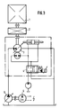
- FIG. 3 of the drawings attached here there is already a test device for internal combustion engines, which has a hydrostatic unit with secondary control instead of an electrical direct current machine operating alternately as a motor or as a generator.
- This test device is much cheaper and structurally simpler than the devices with electrical machines. While electrical machines have a mass moment of inertia many times greater than that of internal combustion engines, as mentioned 5 to 25 times larger, hydrostatic machines have a smaller moment of inertia than internal combustion engines.
- the term (internal combustion engines) or (internal combustion engines) is understood to mean gasoline engines, diesel engines and internal combustion engines.
- an internal combustion engine (1) is connected via a reduction gear (2) to a secondary-controlled hydraulic unit (3), the speed setting of which is coupled to a gas pedal via a proportional valve (4);
- a correspondingly small swivel angle is set on the hydraulic unit (3), which means the setting of a small delivery volume and which is necessary in order to support the torque emitted by the internal combustion engine (1) at a constant operating pressure of the hydrostatic fluid.
- the amount of hydrostatic fluid delivered usually oil. If the speed is increased, the delivery rate increases with the same swivel angle.
- the torque of the internal combustion engine (1) is determined by the position of its throttle valve.
- the hydraulic unit (3) which is also referred to as the secondary unit, reacts to an increase in the engine torque with the reaction torque by increasing the swivel angle, the delivery rate also increasing when the speed input is constant.
- the operating pressure in the system remains constant during this process. It is regulated and adjusted on a second hydraulic unit (5) which, acting as a motor, drives an electric motor (6).
- the electric motor can be a three-phase asynchronous motor. It is forced into the oversynchronous speed range by the second hydraulic unit (5) working as a motor, works as a generator and feeds electricity back into the power grid.
- the pressure-controlled second hydraulic unit (5) works as a pump
- the first, hydraulic unit (3) which can be designated as a secondary unit, as a motor for driving the internal combustion engine (1).
- the object of the invention is to provide a drive and brake system for the test device which, with as little effort as possible, enables realistic simulation of even very small moments of inertia and, at the same time, precise control and adjustment of the desired load on the test specimen, including the
- the requirement to be taken into account is to simulate moments of inertia in a very wide range and with high accuracy, while at the same time keeping the construction effort small.
- the hydrostatic brake and drive machine works as a pump in braking mode and as a motor in driving mode. To regulate its flow rate, it is connected to a hydraulic switching device with controllable, fast servo valves and servo pistons and preferably works in a closed hydrostatic fluid circuit.
- the most important feature is the extremely rapid change in torque, which is achieved by adjusting the swivel angle and thus the delivery volume of the hydrostatic brake and drive machine.
- the delivery volume is controlled and regulated by one or more electrohydraulic control loops.
- the instantaneous acceleration of the test specimen is preferably continuously measured on the drive train between the drive machine and the test specimen, the required simulation torque and its direction of action are determined via a controller, and a corresponding setpoint signal is then fed to the control loop.
- the controller adjusts the hydrostatic brake and drive machine in such a way that the electronically measured actual torque value matches the target value and the test specimen is thus subjected to the correct instantaneous torque load.
- the hydrostatic brake and drive machine can contain one or more hydraulic units.
- the static load torque can be set according to a predetermined program that the sum of the static load torque plus simulation torque equal to the total torque M ges acting at any time on the DUT.
- the "static load torque" is the torque of the test object during operation without changing the speed.
- the real flywheel masses can optionally be coupled with the hydrostatic brake and drive machine.
- the size, or the number of hydrostatic units required to form the hydrostatic brake and drive machine is essentially determined by the size of the mass torque to be simulated. If the mass required in each case can be represented in a relatively fine-scale manner by flywheels, only a small portion (approx. 10% to 25%) of the total mass has to be generated by simulation. This solution results in significantly smaller torques that must be generated by the hydrostatic brake and drive machine, so that their units can be made much smaller and cheaper.
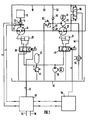
- a test object 12 is connected to a hydrostatic brake and drive machine 16 via a drive shaft 14.
- the machine 16 is a hydraulic unit which, depending on the torque direction of the drive shaft 14, works as a pump or as a motor and, depending on the direction of rotation of the drive shaft 14, conveys the hydraulic fluid in one direction or another through a hydraulic energy circuit 18 or from this in one direction or the other receives the hydraulic fluid.
- the hydraulic unit 16 is a component of the closed energy circuit 18.
- the two hydraulic units 16 and 22 operate alternately as a hydraulic pump and hydraulic motor, with one operating as a hydraulic pump when the other operating as a hydraulic motor and vice versa.
- the second hydraulic unit 22 converts the braking energy of the first hydraulic unit 16, when it works as a pump, into electrical energy by driving an electrical machine 24, which functions as a generator and supplies electrical current to the electrical network. This state is present when the device under test 12 drives the first hydraulic unit 16.
- the electrical machine 24 works as an electric motor which drives the second hydraulic unit 22, which thereby works as a pump and supplies hydraulic fluid to the first hydraulic unit 16 working as a motor. If the first hydraulic unit 16 only works as a pump in order to generate braking energy for braking the test specimen 12, then a pressure regulating valve acting as a flow restrictor to destroy the braking energy can be installed in the line system 20 instead of the second hydraulic unit 22.
- the swivel angle of the hydraulic unit 16, and thus the delivery volume of this hydraulic unit 16, is adjusted via an adjusting cylinder 26 by a servo valve 28, which is controlled by a controller 30.
- the control by the controller 30 takes place as a function of the torque on the drive shaft 14, for which purpose a torque transducer 32 of the controller 30 is arranged on the drive shaft 14.
- the controller 30 is also given the size of the mass to be simulated, which is represented by a line 34, and a static load value, which corresponds to the static load value on the drive shaft 14 if there is no acceleration or deceleration of its speed, which is indicated by a line 36 is shown symbolically on the controller 30.
- the controller 30 Depending on the determination of the speed change per unit of time on the drive shaft 14, which is determined by the speed sensor 31, and depending on the predetermined value of the mass size to be simulated and the value of the static load, the controller 30 generates on its electrical control line 33 an electrical setpoint signal for the servo valve 28, according to which the swivel angle of the hydraulic unit 16 is adjusted via the servo valve 28 and the adjusting cylinder so that this hydraulic unit 16 generates a torque corresponding to a flywheel mass to be simulated.
- This simulated flywheel mass can be larger or smaller than the mass actually present in practice, depending on the specifications for the controller 30 on the lines 34 and 36.
- the control pressure fluid for the adjusting cylinder 26 is taken from a sump 40 by a servo pump 38 by a Pressure relief valve 44 and a pressure accumulator 42 are kept constant and fed to the adjusting cylinder 26 via the servo valve 28.
- the servo pump 38 also delivers control pressure fluid to a second servo valve 48, which adjusts the swivel angle and thus the delivery volume of the second hydraulic unit 22 via a second adjusting cylinder 26.
- the second hydraulic valve 48 is controlled and regulated by a second controller 50, which operates as a function of the first controller 30.
- a pump 52 driven by the hydraulic unit 22 sucks hydraulic fluid from the sump 40 via a line 54 and renews leakage fluid in the line system 20 of the energy circuit 18 on both sides of the connections of the hydraulic units 16 and 22 via lines 56 and 58 with one-way valves 60.
- a valve 62 between the two One-way valves 60 maintain a constant pressure at the outlet of the pump 52.
- a heat exchanger 64 is located in the suction line 54 of the pump 52.
- a flushing valve 66 leads excess hydraulics from the energy circuit 18 back into the sump 40.
- the controller 30 can be entered by a computer with variable load values which correspond to the load values of the test object 12 which occur in practice.
- hydraulic unit 16 instead of a single hydraulic unit 16, several hydraulic units can also be combined with one another. The same applies to the hydraulic unit 22.
- the swivel angle and thus the delivery volume of the hydraulic units 16 and 22 can be independent from each other or depending on each other, depending on the requirements of the test facility in practice.
- the device under test 12 can be an internal combustion engine, a transmission, a gear, a clutch, a brake, a vehicle axle, a drive shaft and the like drive element. Depending on the type of test object, it is alternately driven by different flywheels or it drives these flywheels. These flywheel masses are simulated by the hydraulic unit 16.
- the simulation with a hydraulic unit is much more precise, and it follows torque changes much faster than electric motor / generator machines for mass simulation. Electrical machines also have the disadvantage that they overshoot the control value during control operations, while such overshoot of the control operations can be largely avoided with hydraulic units. However, even with hydraulic units, a small residual error, particularly with high acceleration values, cannot be completely avoided. Therefore, according to the invention according to FIG.
- FIG. 2 A particularly advantageous embodiment according to the invention is shown in FIG. 2, in which the flywheels existing in practice are replaced by two flywheels 70 and 72 as real flywheels and are simulated by two hydraulic units 16.
- the real flywheel masses 70 and 72, together with the flywheel masses simulated by the hydraulic units 16 can be set to be the same size, smaller or larger than the flywheel masses that actually exist in practice and interact with the test specimen 12.
- two hydraulic units 16 it is of course also possible to use only one or more which are drivingly connected to the drive shaft 14 via a common output shaft 74 with a gear 76 fastened thereon via a gear 78.
- the two gear wheels 78 and 80 have different diameters and are therefore in engagement with different gear ratios with gear wheels 82 and 84 of different sizes, which are rotatably mounted on a connecting shaft 86, with which they are each connected in a rotationally fixed manner via a coupling 88 or 90 can.
- the connecting shaft 86 is selectively or simultaneously rotatably connected via couplings 92 and 94 to one or the other or both flywheels 70 and 72.
- the flywheels 70 and 72 are rotatably supported on a gear housing 96 by bearings 98.
- the gears 78 to 84 together with the clutches 88 and 90 form a two-stage gear 97.
- Such a combination of real flywheel masses and additionally flywheel masses simulated by the hydraulic unit or hydraulic units 16 results in a considerable reduction in the construction effort for the flywheel mass simulation and a more accurate replication of the respectively desired flywheel mass.
- the size and the number of the required hydraulic units 16 are essentially determined by the required flywheel mass and thus also by the required simulation torque. If the flywheel mass required in each case can already be finely represented by flywheels, only a small proportion, for example from 10% to 25%, of the total flywheel mass has to be generated by simulation. This solution with real flywheel masses as a replacement for the existing flywheel masses in practice enables the use of hydraulic units which have a considerably lower torque and are therefore smaller and cheaper.
Landscapes
- Physics & Mathematics (AREA)
- General Physics & Mathematics (AREA)
- Chemical & Material Sciences (AREA)
- Engineering & Computer Science (AREA)
- Combustion & Propulsion (AREA)
- Testing Of Devices, Machine Parts, Or Other Structures Thereof (AREA)
- Testing Of Engines (AREA)
- Testing Electric Properties And Detecting Electric Faults (AREA)
- Power Steering Mechanism (AREA)
Claims (1)
- Dispositif d'essai d'unités d'entraînement, d'éléments constitutifs d'entraînements ou de combinaisons de ces derniers, ci-après désignés par "objet testé", comprenant- une machine hydrostatique (16) de freinage et d'entraînement pouvant fonctionner alternativement comme une pompe ou un moteur, avec volume refoulé variable, et pouvant être mise en liaison avec l'objet testé, par l'intermédiaire d'un segment d'entraînement, et- un dispositif de réglage (26, 28, 30) pour ajuster le volume refoulé en fonction d'un couple de rotation devant être engendré par la machine hydrostatique de freinage et d'entraînement,caractérisé par les particularités suivantes :- la masse d'inertie nécessaire à un examen correct de l'objet testé (12) est simulée, au moins partiellement, par une variation rapide, dépendant de l'accélération positive ou négative de l'objet testé, du couple de rotation de la machine hydrostatique (16) de freinage et d'entraînement ;- un circuit de régulation très rapide (16, 26, 28, 30, 32), servant à faire varier le couple de rotation de la machine hydrostatique (16) de freinage et d'entraînement, ajuste la quantité refoulée par ladite machine hydrostatique (16) de freinage et d'entraînement fonctionnant dans un circuit d'énergie hydraulique (18), par l'intermédiaire d'un régulateur électronique (30) et du piston hydraulique asservi d'un vérin de réglage (26), en fonction de l'accélération rotatoire de l'objet testé (12) à l'instant considéré, de manière à engendrer, à chaque instant, la contrainte quasi statique souhaitée de l'objet testé, présente en l'absence d'accélération et en l'absence de ralentissement, avec génération additionnelle du couple de rotation nécessaire à l'accélération ou au ralentissement d'une masse préétablie ;- la masse d'inertie, pouvant être simulée par la machine hydrostatique (16) de freinage et d'entraînement, peut être ajustée en continu ou au moins avec progression fine ;- au moins deux masses d'inertie effectives (70, 72) pouvant être mises en circuit, prévues pour la simulation d'une part supplémentaire de la masse d'inertie nécessaire à l'examen correct de l'objet testé (12), peuvent être sélectivement combinées, individuellement ou en combinaison, à la masse d'inertie simulée de la machine hydrostatique (16) de freinage et d'entraînement ;- la masse d'inertie, revêtant la forme de masses d'inertie effectives (70, 72), est supérieure à la masse d'inertie pouvant être simulée à l'aide de la machine hydrostatique (16) de freinage et d'entraînement ; et- deux masses d'inertie (70, 72) différemment grandes peuvent être reliées à l'objet testé (12), par l'intermédiaire d'une transmission sélective (97) à deux paliers, de telle sorte que puissent être engendrés, au total, sept masses d'inertie différentes et des couples d'inertie de masse correspondants agissant sur l'objet testé (12).
Priority Applications (1)
| Application Number | Priority Date | Filing Date | Title |
|---|---|---|---|
| AT87106915T ATE83074T1 (de) | 1986-07-10 | 1987-05-13 | Pruefeinrichtung fuer antriebseinheiten. |
Applications Claiming Priority (2)
| Application Number | Priority Date | Filing Date | Title |
|---|---|---|---|
| DE3623264 | 1986-07-10 | ||
| DE3623264A DE3623264C1 (de) | 1986-07-10 | 1986-07-10 | Pruefeinrichtung fuer Antriebseinheiten |
Publications (4)
| Publication Number | Publication Date |
|---|---|
| EP0252246A2 EP0252246A2 (fr) | 1988-01-13 |
| EP0252246A3 EP0252246A3 (en) | 1990-04-25 |
| EP0252246B1 EP0252246B1 (fr) | 1992-12-02 |
| EP0252246B2 true EP0252246B2 (fr) | 1995-09-06 |
Family
ID=6304863
Family Applications (1)
| Application Number | Title | Priority Date | Filing Date |
|---|---|---|---|
| EP87106915A Expired - Lifetime EP0252246B2 (fr) | 1986-07-10 | 1987-05-13 | Dispositif d'essay d'unités d'entraînement |
Country Status (4)
| Country | Link |
|---|---|
| US (1) | US4807467A (fr) |
| EP (1) | EP0252246B2 (fr) |
| AT (1) | ATE83074T1 (fr) |
| DE (2) | DE3623264C1 (fr) |
Cited By (1)
| Publication number | Priority date | Publication date | Assignee | Title |
|---|---|---|---|---|
| DE102019133393A1 (de) * | 2019-12-06 | 2021-06-10 | TDK Europe GmbH | Hydraulische Vorrichtung zur Prüfung der elektromagnetischen Verträglichkeit und/oder anderer Eigenschaften eines Elektromotors |
Families Citing this family (34)
| Publication number | Priority date | Publication date | Assignee | Title |
|---|---|---|---|---|
| US4928519A (en) * | 1988-09-28 | 1990-05-29 | Vehicle Safety Controls, Inc. | Brake testing apparatus |
| US4920788A (en) * | 1988-11-21 | 1990-05-01 | Mitsuboshi Belting Ltd. | Rotation variation testing machine |
| US5103671A (en) * | 1990-11-28 | 1992-04-14 | Sauer, Inc. | Hydrostatic test stand |
| US5708342A (en) * | 1993-05-27 | 1998-01-13 | Fanuc Ltd. | Method of controlling acceleration/deceleration time constants for robot |
| JPH10508685A (ja) * | 1994-08-24 | 1998-08-25 | インダストリアル リサーチ リミテッド | コンピュータ化された制御システムを有するダイナモメータ |
| DE19647513A1 (de) * | 1996-11-16 | 1998-05-20 | Schenck Komeg Gmbh | Rotierbare Schwungscheibenaufnahme |
| DE19748778B4 (de) * | 1997-11-06 | 2007-08-09 | Volkswagen Ag | Lagervorrichtung für einen Triebsatzprüfstand |
| DE10037412C2 (de) | 2000-08-01 | 2002-08-01 | Teamtechnik Maschinen Und Anla | Antriebs- und Getriebeprüfstand |
| US6708557B2 (en) * | 2002-02-13 | 2004-03-23 | Wisconsin Alumni Research Foundation | Internal combustion engine simulation and testing |
| US7165465B2 (en) * | 2004-09-29 | 2007-01-23 | Raytheon Company | Dynamic load fixture for application of torsion loads for rotary mechanical systems |
| US20060234829A1 (en) * | 2005-04-13 | 2006-10-19 | Ford Global Technologies, Llc | System and method for inertial torque reaction management |
| DE102005035295B4 (de) * | 2005-07-28 | 2016-12-29 | Audi Ag | Prüfstand für eine Verbrennungskraftmaschine mit einer Anbindungsvorrichtung für eine Kurbelwelle |
| DE502005006573D1 (de) * | 2005-11-02 | 2009-03-19 | Ford Global Tech Llc | Hydraulischer Schlupfsimulator und Verfahren zum Betreiben eines hydraulischen Schlupfsimulators |
| DE202007014676U1 (de) | 2007-10-19 | 2009-02-26 | Liebherr-Machines Bulle S.A. | Hydraulisches Antriebssystem |
| DE102007057052B4 (de) * | 2007-11-27 | 2013-09-19 | Bayerische Motoren Werke Aktiengesellschaft | Schwenkprüfstand |
| US8447554B2 (en) * | 2009-09-28 | 2013-05-21 | Mohammed Reza Emami | System, method and computer program for remotely testing system components over a network |
| US9404834B2 (en) | 2012-03-28 | 2016-08-02 | Borealis Technical Limited | Active resistance dynamometer for wheel testing |
| DE102014116770B3 (de) * | 2014-11-17 | 2016-04-07 | Industrieanlagen- Betriebsgesellschaft mit beschränkter Haftung | Prüfstand und Verfahren zum Prüfen von federnden Elementen |
| CN105675292B (zh) * | 2014-11-21 | 2018-05-18 | 中国科学院沈阳自动化研究所 | 一种变速箱空载试验惯量加载机构 |
| DE102015120652A1 (de) * | 2015-11-27 | 2017-06-01 | Kurt Stimpfl | Prüfeinrichtung für Elektroantriebe |
| RU2664718C2 (ru) * | 2016-02-02 | 2018-08-22 | Азер Ядуллаевич Гулиев | Стенд для обкатки двигателей внутреннего сгорания |
| US10208455B2 (en) | 2016-03-17 | 2019-02-19 | Deere & Company | In-vehicle dynometer |
| CN105823633A (zh) * | 2016-05-19 | 2016-08-03 | 龙工(上海)精工液压有限公司 | 液压马达惯性加载试验装置 |
| CN107463717A (zh) * | 2016-06-03 | 2017-12-12 | 罗伯特·博世有限公司 | 用于求取传动系的总质量惯性矩的方法 |
| DE102016210440A1 (de) * | 2016-06-13 | 2017-12-14 | Zf Friedrichshafen Ag | Bremsenprüfsystem zur Prüfung einer Bremse für ein Fahrzeug |
| CN109426150B (zh) * | 2017-08-25 | 2021-11-09 | 南京理工大学 | 基于扩张状态观测器的负载模拟器反步控制方法 |
| CN107345856A (zh) * | 2017-09-07 | 2017-11-14 | 中国船舶重工集团公司第七〇九研究所 | 一种用于旋转轴系的低动刚度纵向加载激振装置 |
| CN108195582A (zh) * | 2018-03-31 | 2018-06-22 | 西北农林科技大学 | 一种静液压驱动履带拖拉机传动系统性能测试试验台 |
| CN110608895B (zh) * | 2019-09-12 | 2022-05-31 | 吉林省瑞普测控技术有限公司 | 一种整车制动系统模拟动态性能测试系统 |
| DE102019133256A1 (de) * | 2019-12-05 | 2021-06-10 | Knorr-Bremse Systeme für Schienenfahrzeuge GmbH | Verfahren und Vorrichtung zur Prüfung eines Bremssystems für ein Schienenfahrzeug |
| CN112268036B (zh) * | 2020-10-16 | 2023-03-24 | 中国直升机设计研究所 | 一种用于模拟直升机apu起动负载的装置 |
| CN112213106B (zh) * | 2020-10-16 | 2022-07-29 | 中国直升机设计研究所 | 一种直升机apu起动载荷模拟系统 |
| CN113281024B (zh) * | 2021-05-13 | 2022-09-02 | 广西防城港核电有限公司 | 汽轮机液压盘车离线检测方法 |
| CN118625128B (zh) * | 2024-07-08 | 2024-11-19 | 中国地质大学(北京) | 电机自动刹车测试系统及方法 |
Family Cites Families (6)
| Publication number | Priority date | Publication date | Assignee | Title |
|---|---|---|---|---|
| US2982128A (en) * | 1957-09-25 | 1961-05-02 | Gen Electric | Dynamometer control system |
| US3712127A (en) * | 1970-08-11 | 1973-01-23 | Mts System Corp | Drive train test stand |
| DE2740197A1 (de) * | 1977-09-07 | 1979-03-08 | Hurth Masch Zahnrad Carl | Hydraulische verspannungseinrichtung |
| US4274281A (en) * | 1978-09-27 | 1981-06-23 | Hoodwin Louis S | Hydraulic testing system |
| DE3347182A1 (de) * | 1983-12-27 | 1985-07-04 | Siemens AG, 1000 Berlin und 8000 München | Verfahren zur schwungmassensimulation bei pruefstaenden |
| DE3501342A1 (de) * | 1985-01-17 | 1986-07-17 | Daimler-Benz Ag, 7000 Stuttgart | Hydrostatischer pruefstand fuer fahrzeuggetriebe |
-
1986
- 1986-07-10 DE DE3623264A patent/DE3623264C1/de not_active Expired - Fee Related
-
1987
- 1987-05-13 AT AT87106915T patent/ATE83074T1/de not_active IP Right Cessation
- 1987-05-13 DE DE8787106915T patent/DE3782866D1/de not_active Expired - Fee Related
- 1987-05-13 EP EP87106915A patent/EP0252246B2/fr not_active Expired - Lifetime
- 1987-07-08 US US07/070,908 patent/US4807467A/en not_active Expired - Fee Related
Cited By (1)
| Publication number | Priority date | Publication date | Assignee | Title |
|---|---|---|---|---|
| DE102019133393A1 (de) * | 2019-12-06 | 2021-06-10 | TDK Europe GmbH | Hydraulische Vorrichtung zur Prüfung der elektromagnetischen Verträglichkeit und/oder anderer Eigenschaften eines Elektromotors |
Also Published As
| Publication number | Publication date |
|---|---|
| EP0252246A2 (fr) | 1988-01-13 |
| DE3623264C1 (de) | 1993-02-11 |
| US4807467A (en) | 1989-02-28 |
| EP0252246B1 (fr) | 1992-12-02 |
| EP0252246A3 (en) | 1990-04-25 |
| DE3782866D1 (de) | 1993-01-14 |
| ATE83074T1 (de) | 1992-12-15 |
Similar Documents
| Publication | Publication Date | Title |
|---|---|---|
| EP0252246B2 (fr) | Dispositif d'essay d'unités d'entraînement | |
| DE2915914A1 (de) | Hydrauliksystem fuer die uebertragung von leistung von einer brennkraftmaschine auf raeder eines kraftfahrzeugs | |
| DE3152541A1 (en) | A method of automatic gear selection in a vehicle power transmission | |
| EP0088925B1 (fr) | Dispositif pour la régulation d'une unité de propulsion pour véhicules automobiles | |
| DE69529560T2 (de) | Verfahren zum Festsetzen der Bremsen während des automatischen Bremsens | |
| WO1986002608A1 (fr) | Arrangement d'entrainement pour vehicules a moteur utilitaires | |
| DE3144902A1 (de) | "antriebsaggregat mit einem schaltgetriebe" | |
| DE3443064C2 (de) | Automatisches Kupplungssteuersystem | |
| DE2322256A1 (de) | Laststeuervorrichtung fuer einen hydraulischen rotations-leistungsaufnehmer | |
| EP1452848A1 (fr) | Méthode de commande d'un banc d'essai pour moteur | |
| DE2448723A1 (de) | Wandleraggregat fuer verbrennungsmotoren | |
| DE2462058C3 (de) | Wandleraggregat für Verbrennungskraftmaschinen | |
| WO1997019765A1 (fr) | Dispositif de reglage pour vibrateur a balourd avec couple centrifuge reglable | |
| DE3433494A1 (de) | Fahr-antriebsvorrichtung fuer maschinen und fahrzeuge, bevorzugt fuer baufahrzeuge wie radlader | |
| AT398009B (de) | Regeleinrichtung für einen prüfstand | |
| DE4238802A1 (fr) | ||
| DE2057347C3 (de) | Vorrichtung zur Prüfung umlaufender Werkstücke bezüglich ihres Verhaltens bei unterschiedlichen Drehzahlen und Drehmomenten | |
| DE19914606C2 (de) | Vorrichtung und Verfahren zum Prüfen von hydrostatischen Verdrängungseinheiten im Betriebszustand | |
| EP0098570A2 (fr) | Dispositif d'essai d'un générateur de couple | |
| DE19613042C2 (de) | Pumpen-Prüfstand mit Energie-Rückgewinnung | |
| DE3609399C2 (fr) | ||
| EP1879777B1 (fr) | Procede d'ajustement d'une courbe caracteristique de freinage pour un ralentisseur de vehicule a moteur | |
| DE3501342A1 (de) | Hydrostatischer pruefstand fuer fahrzeuggetriebe | |
| DE3031232A1 (de) | Verfahren und vorrichtung zum uebertragen und/oder speichern von rotationsenergie | |
| DE2545778C3 (de) | Hydrostatisches Getriebe |
Legal Events
| Date | Code | Title | Description |
|---|---|---|---|
| PUAI | Public reference made under article 153(3) epc to a published international application that has entered the european phase |
Free format text: ORIGINAL CODE: 0009012 |
|
| 17P | Request for examination filed |
Effective date: 19870604 |
|
| AK | Designated contracting states |
Kind code of ref document: A2 Designated state(s): AT DE FR GB IT |
|
| PUAL | Search report despatched |
Free format text: ORIGINAL CODE: 0009013 |
|
| AK | Designated contracting states |
Kind code of ref document: A3 Designated state(s): AT DE FR GB IT |
|
| 17Q | First examination report despatched |
Effective date: 19910508 |
|
| GRAA | (expected) grant |
Free format text: ORIGINAL CODE: 0009210 |
|
| AK | Designated contracting states |
Kind code of ref document: B1 Designated state(s): AT DE FR GB IT |
|
| PG25 | Lapsed in a contracting state [announced via postgrant information from national office to epo] |
Ref country code: IT Free format text: LAPSE BECAUSE OF FAILURE TO SUBMIT A TRANSLATION OF THE DESCRIPTION OR TO PAY THE FEE WITHIN THE PRE;WARNING: LAPSES OF ITALIAN PATENTS WITH EFFECTIVE DATE BEFORE 2007 MAY HAVE OCCURRED AT ANY TIME BEFORE 2007. THE CORRECT EFFECTIVE DATE MAY BE DIFFERENT FROM THE ONE RECORDED.SCRIBED TIME-LIMIT Effective date: 19921202 Ref country code: FR Effective date: 19921202 Ref country code: GB Effective date: 19921202 |
|
| REF | Corresponds to: |
Ref document number: 83074 Country of ref document: AT Date of ref document: 19921215 Kind code of ref document: T |
|
| REF | Corresponds to: |
Ref document number: 3782866 Country of ref document: DE Date of ref document: 19930114 |
|
| EN | Fr: translation not filed | ||
| PG25 | Lapsed in a contracting state [announced via postgrant information from national office to epo] |
Ref country code: AT Effective date: 19930513 |
|
| GBV | Gb: ep patent (uk) treated as always having been void in accordance with gb section 77(7)/1977 [no translation filed] |
Effective date: 19921202 |
|
| PLBI | Opposition filed |
Free format text: ORIGINAL CODE: 0009260 |
|
| 26 | Opposition filed |
Opponent name: MANNESMANN REXROTH GMBH Effective date: 19930618 |
|
| PUAH | Patent maintained in amended form |
Free format text: ORIGINAL CODE: 0009272 |
|
| STAA | Information on the status of an ep patent application or granted ep patent |
Free format text: STATUS: PATENT MAINTAINED AS AMENDED |
|
| 27A | Patent maintained in amended form |
Effective date: 19950906 |
|
| AK | Designated contracting states |
Kind code of ref document: B2 Designated state(s): AT DE FR GB IT |
|
| EN | Fr: translation not filed | ||
| PGFP | Annual fee paid to national office [announced via postgrant information from national office to epo] |
Ref country code: DE Payment date: 20000422 Year of fee payment: 14 |
|
| PG25 | Lapsed in a contracting state [announced via postgrant information from national office to epo] |
Ref country code: DE Free format text: LAPSE BECAUSE OF NON-PAYMENT OF DUE FEES Effective date: 20020301 |