EP0251032B1 - Packing or unpacking machine - Google Patents
Packing or unpacking machine Download PDFInfo
- Publication number
- EP0251032B1 EP0251032B1 EP87108697A EP87108697A EP0251032B1 EP 0251032 B1 EP0251032 B1 EP 0251032B1 EP 87108697 A EP87108697 A EP 87108697A EP 87108697 A EP87108697 A EP 87108697A EP 0251032 B1 EP0251032 B1 EP 0251032B1
- Authority
- EP
- European Patent Office
- Prior art keywords
- gripper
- packing
- carrier
- machine according
- unpacking machine
- Prior art date
- Legal status (The legal status is an assumption and is not a legal conclusion. Google has not performed a legal analysis and makes no representation as to the accuracy of the status listed.)
- Expired - Lifetime
Links
- 238000012856 packing Methods 0.000 title claims abstract description 34
- 230000033001 locomotion Effects 0.000 claims abstract description 54
- 238000012546 transfer Methods 0.000 claims abstract description 48
- 239000000969 carrier Substances 0.000 claims description 5
- 238000012423 maintenance Methods 0.000 claims 2
- 230000000717 retained effect Effects 0.000 claims 2
- 238000000151 deposition Methods 0.000 abstract description 2
- 238000010586 diagram Methods 0.000 description 4
- 230000001133 acceleration Effects 0.000 description 3
- 230000005540 biological transmission Effects 0.000 description 2
- 230000007704 transition Effects 0.000 description 2
- 206010034016 Paronychia Diseases 0.000 description 1
- 238000013461 design Methods 0.000 description 1
- 238000001514 detection method Methods 0.000 description 1
- 238000011161 development Methods 0.000 description 1
- 238000006073 displacement reaction Methods 0.000 description 1
- 238000003780 insertion Methods 0.000 description 1
- 230000037431 insertion Effects 0.000 description 1
- 230000035939 shock Effects 0.000 description 1
Images


Classifications
-
- B—PERFORMING OPERATIONS; TRANSPORTING
- B65—CONVEYING; PACKING; STORING; HANDLING THIN OR FILAMENTARY MATERIAL
- B65B—MACHINES, APPARATUS OR DEVICES FOR, OR METHODS OF, PACKAGING ARTICLES OR MATERIALS; UNPACKING
- B65B21/00—Packaging or unpacking of bottles
- B65B21/02—Packaging or unpacking of bottles in or from preformed containers, e.g. crates
- B65B21/14—Introducing or removing groups of bottles, for filling or emptying containers in one operation
- B65B21/18—Introducing or removing groups of bottles, for filling or emptying containers in one operation using grippers engaging bottles, e.g. bottle necks
- B65B21/183—Introducing or removing groups of bottles, for filling or emptying containers in one operation using grippers engaging bottles, e.g. bottle necks the grippers moving in an endless path
Definitions
- the invention relates to a packing or unpacking machine for articles in or from containers, preferably bottles in or from bottle crates, as specified in the preamble of claim 1.
- Such a machine for loading or unloading open bottle crates is known from DE-PS 1 035 559, in which a transfer device for the bottles is arranged on three conveyor tracks arranged parallel to one another, namely a conveyor track leading the bottle crates, and a conveyor track removing the bottle crates and a conveyor track leading the bottles in and out.
- the transfer device contains four transfer units which are moved in a circular path and are assigned to a turntable, each of which has a gripper and carrier head for the bottles and a gripper and carrier device for the bottle crates. With this latter gripper and carrier device, the bottle crates are removed from the conveying path which brings them up, carried along on half of the circular movement path of the transfer unit and then placed on the conveying conveying path.
- the gripper and carrier head for the bottles is lowered and raised again in relation to the gripper and carrier device for the bottle crates, in order to insert or lift the bottles out of the respective bottle crate during the rotating movement of the transfer unit.
- the necessity of removing the bottle crates from a conveyor track and placing them on another conveyor track requires considerable additional effort in this known loading or unloading machine, namely not only with regard to the additional gripper and carrier devices for the bottle crates on the transfer units themselves and on the conveyor lines for the bottle crates required transfer devices or transfer devices for the bottle crates, but above all also with regard to the precise control for the transfer and transfer of the bottle crates. In all this, such known loading and unloading machines can only work slowly in the interest of operational safety, so that only a limited throughput can be achieved.
- the object of the invention is therefore to significantly improve a loading and unloading machine of the type mentioned in such a way that the containers can remain on their conveyor track during loading or unloading and still have enough time to insert or remove the articles safely into the containers remove the containers while the respective container continues on its conveyor track. Movements that can be derived from pure rotary movements or circular movements should be used that are bumpless and as free as possible of abrupt movement transitions. This object is achieved by the measures represented in the characterizing part of claim 1:
- the loading or unloading machine is characterized by a simple structure, simple development of the movement on the gripper and carrier head for the articles and by smooth and continuous movement deflection on the gripper and carrier head.
- the gripper and carrier head When viewed from above, the gripper and carrier head always remain in their parallel position with respect to the conveyor tracks.
- the movement transitions on the gripper and carrier heads during the rotation of the transfer unit correspond to a sine line.
- the transfer units can be moved on a circular track and can therefore be attached to a machine part rotating in a circular motion, for example in the manner of a round carousel. Above all, any tension elements, such as chains and the like. be avoided for the movement of the transfer units in orbit.
- the gripper and carrier heads are not arranged in a straight line above the conveyor tracks, this means no difficulty for picking up or setting down the items on the corresponding item conveyor track, but for the exact insertion of the items in a container or the safe removal of articles from a bundle, a slight lateral displacement of the bundle on its conveyor track can easily be carried out, in particular by means of additional measures as specified in claims 12 to 16.
- the packing or unpacking machine according to the invention ne can be optionally formed with a central drive column or with a free central area, the latter is specified in claim 11.
- the packing or unpacking machine has a gate-like machine frame 11, through which a conveyor track 12 for articles, namely bottles 13, and a conveyor track 14 for containers, namely bottle crates 15, are guided parallel to one another.
- the machine frame 11 carries on its upper part a machine housing 16 in which a number of, for example, six transfer units 17 with gripper and carrier heads 30 held on lifting and lowerable carriers 1 are guided on a circular path K for carrying out a main circulating movement and are connected to corresponding drive devices .
- the drive movement is taken up by a drive device 18 arranged in the lower part between the machine frame 11 and transmitted via a vertical cardan shaft 19.
- the drive device 18 is also provided for driving the conveyor track 12 for feeding the bottles 13 and for driving the conveyor track 14 which feeds the empty bottle crates 15 and discharges the filled bottle crates 15 and is located lower than the track plane of the conveyor track 12.
- the transfer units 17 are attached to a ring plate 2 of a cup-shaped turntable 20 rotatably mounted in the machine housing 16 with a ball joint 3, the toothed ring 4 of which is formed on the rotating bearing part of the ball joint 3 with the interposition of a gear wheel 5 via a drive shaft 19 driven gear 21 is set in continuous rotary motion, whereby the transfer units 17 and thus their lifting and lowering carriers 1 are given a continuous orbital motion on the circular path K.
- each transfer unit 17 has an outer, preferably cylindrical, housing 22, which is firmly inserted into the ring plate 2 of the turntable 20.
- An inner guide housing 23 is mounted axially displaceably within this outer housing 22.
- This guide housing 23 accommodates a vertical main shaft 24, the axis of this main shaft 24 also forming the vertical axis 26 of the transfer unit 17 or of the liftable and lowerable carrier 1, which travels on the circular path K (see FIGS. 5 and 7).
- the guide housing 23 contains an axially and radially effective bearing 27 for the main shaft 24.
- a control roller 28 is attached laterally into the guide housing 23 and is used to generate the lifting and lowering movements for the one essentially from the guide housing 23 and the main shaft 24 consisting of the gripper and carrier head 30 holding and lowerable carrier 1 rotates on a control path 29 assigned to the fixed part of the machine housing 16 as it is dashed in FIG. 1 and indicated in dash-dot lines in FIGS.
- the shaft region 35 of the main shaft 24 is designed in the manner of a splined shaft and is guided axially displaceably in a hub of a planet wheel 36 adapted to this, this planet wheel 36 by means of radial roller bearings 37 in upper end of the outer casing ses 22 is held rotatably.
- a swivel arm 38 is fixedly mounted, in which an intermediate gear 39 meshing in the sun gear 33 (see FIGS. 3, 5 and 7) is mounted, in which a planet gear 40 meshes.
- the planet gear 40 forms a further epicyclic gear UW which ensures the parallel position of the gripper and carrier head 30 and which is part of the drive device of the movement device for generating the superimposed relative movement.
- the planet gear 40 is fixedly connected to an output pin 41 rotatably mounted in the swivel arm 38, which is arranged vertically and supports the gripper and carrier head 30 at its lower end.
- the rotary movement of the planetary wheel 36 can take place in different ways.
- a central, fixed gearwheel 42 is arranged inside the machine housing 16 and is fastened on a pin 7 mounted in the upper circular plate 6 of the turntable 20.
- This pin 7 carries with its via the fixed gear 42 upward end a usual to a compressed air source connected distributor 8 for supplying the gripper and carrier heads 30 with compressed air and is by means of an arm 9 above the distributor 8 with the fixed part of the Machine housing 16 connected so that the fixed gear 42 and the stationary part of the distributor 8 are secured against rotation and are thus fixed when the turntable 20 rotates.
- an intermediate gear 43 meshing with the fixed gear 42 is provided, with the fixed gear 42, the planet gears 36 and the intermediate gears 43 and the rotary table 20 being a common epicyclic gear UG assigned to the drive device of the movement device for generating the superimposing relative movement Movement of the swivel arms 38 of the lifting and lowering carrier 1 and thus the gripper and carrier heads 30 form.
- the transmission ratios from the fixed gear 42 to the planet gear 36 are such that the planet gear 36 makes one revolution against the direction of rotation of the transfer units 17 with each revolution around the gear 42.
- the swivel arm 38 thus executes one revolution in the opposite direction (FIGS. 4 to 6) or in the same direction (FIGS.
- the distance can also be the same size if, for. B. the conveyor belts 12, 14 have the same altitude.
- the embodiment according to FIG. 7 relates to a common epicyclic gear UG designed for rotating the swivel arm 38 and the transfer unit 17 in the same direction.
- the main shaft 24 is driven by means of an orbital gear 43 'which meshes directly with a fixed gear 44 and a non-slip drive, for example a toothed belt drive, for which purpose a toothed belt pulley 36' is assigned to the drive wheel 43 'and with it the main shaft 24, the meshing idler gear 36 is replaced by a toothed belt pulley 36 'and a toothed belt 46 is provided as a power transmission means.
- a rotational movement in the same direction as the arrow 47 according to the arrow 47 is generated on the toothed belt pulley 36 ′ and consequently on the main shaft 24, while the transfer unit 17 runs once around the vertical central axis 50.
- FIGS. 6 and 8 show that in both embodiments the feed speed of the gripper and carrier head 30 on its movement path 48 or 49 fluctuates depending on the current angular position of the transfer unit 17 in the sense of a sine curve.
- the curve for the acceleration of the gripper and carrier head 30 is also continuous. This means that the entire sequence of movements of the gripper and carrier head 30 in its orbit 48 and 49 is continuous and bumpless.
- the slight differences between the curves shown in FIG. 6 for the embodiment according to FIGS. 4 to 6 and the curves shown in FIG. 8 for the embodiment according to FIG. 7 are insignificant compared to this basic operating behavior.
- each gripper and carrier head 30 provided with a number of conventional gripper elements 58 corresponding to the bottles 13 to be accommodated is equipped with a liftable and lowerable, additional gripping and aligning device 51 which has a centering frame 52 when it is lowered over the opening edge of the respective container or bottle crate 15.
- This centering frame 52 is attached to a pair of guide rods 53 which is suspended from its guide bearing on the gripper and carrier head 30 and has a guide element 54, which can be a slider or a roller.
- the guide element 54 forms a control element which, as is apparent from FIGS. 1 and 2, via stationary control guide tracks 56, 57 held on the machine frame 11 and machine box 16 or, as shown in FIG.
- the frames 52 can already be lowered to such an extent that they offer the bottles 13 an additional hold during further transport to the guide track 14.
- compressed air is applied to them, for which purpose a cam 64 fastened on a shoulder 63 of the swivel arm 38 also receiving the cup curve 62 actuates a valve 65 attached to the top of the gripper and carrier head 30 to establish a connection from a compressed air supply line 66 connected to the rotating part of the distributor 8 to a line 67 connecting the gripper elements 58; see. Fig. 9.
- connection existing for the detection of the group of bottles 13 between the supply line 66 of the line 67 and the line 67 via the valve 65 are interrupted by the running cam 64 from the rotating cam 64 opened to vent the gripper elements 58 to the atmosphere.
- an allocation device 59 is provided in the entrance area of the conveyor track 14 for the bottle crates 15, each of which provides a bottle crate 15 for each gripper and guide head 30 that is loaded with bottles 13.
- FIG. 1 it is a packing machine with which groups of bottles 13 are used in bottle crates 15.
- an unpacking machine is also to be designed, with which groups of bottles 13 can be removed from bottle crates 15 and placed on a removal conveyor.
- the transport directions are to be provided essentially the same as indicated by the arrows 60 and 61 in FIG. 1, however, the removal conveyor track will then preferably be continued on the left side in FIG. 1, while it is approached on the right side according to FIG. 1 .
- such a packing and unpacking machine can also be designed for packing or unpacking other groups of articles into other containers or from other containers.
Landscapes
- Engineering & Computer Science (AREA)
- Mechanical Engineering (AREA)
- Specific Conveyance Elements (AREA)
- Control And Other Processes For Unpacking Of Materials (AREA)
- Container Filling Or Packaging Operations (AREA)
- Wrapping Of Specific Fragile Articles (AREA)
- Filling Of Jars Or Cans And Processes For Cleaning And Sealing Jars (AREA)
Abstract
Description
Die Erfindung betrifft eine Ein- oder Auspackmaschine für Artikel in bzw. aus Gebinden, vorzugsweise Flaschen in bzw. aus Flaschenkästen, wie sie im Oberbegriff des Anspruchs 1 angegeben ist.The invention relates to a packing or unpacking machine for articles in or from containers, preferably bottles in or from bottle crates, as specified in the preamble of
Eine derartige Maschine zum Be- oder Entladen von offenen Flaschenkästen ist aus DE-PS 1 035 559 bekannt, bei der eine Umsetzvorrichtung für die Flaschen an drei parallel zueinander angeordneten Förderbahnen angeordnet ist, und zwar eine die Flaschenkästen heranführende Förderbahn, eine die Flaschenkästen abführende Förderbahn und eine die Flaschen heranführende bzw. abführende Förderbahn. Die Umsetzvorrichtung enthält dabei vier in einer Kreisbahn in Umlauf bewegte, einem Drehtisch zugeordnete Überführungseinheiten, von denen jede einen Greifer- und Trägerkopf für die Flaschen und eine Greifer- und Trägereinrichtung für die Flaschenkästen aufweist. Mit dieser letzteren Greifer- und Trägereinrichtung werden die Flaschenkästen von der sie heranbringenden Förderbahn abgenommen, auf die Hälfte der kreisförmigen Bewegungsbahn der Überführungseinheit mitgenommen und dann auf die abführende Förderbahn abgesetzt. Auf dieser Hälfte der Bewegungsbahn wird der Greifer- und Trägerkopf für die Flaschen gegenüber der Greifer- und Trägereinrichtung für die Flaschenkästen abgesenkt und wieder angehoben, um dabei die Flaschen während der Umlaufbewegung der Überführungseinheit in den jeweiligen Flaschenkasten einzusetzen bzw. aus dem jeweiligen Flaschenkasten herauszuheben. Durch die Notwendigkeit, die Flaschenkästen von einer Förderbahn abzunehmen und auf eine andere Förderbahn aufzusetzen, wird bei dieser bekannten Be-oder Entlademaschine erheblicher zusätzlicher Aufwand bedingt, nämlich nicht nur hinsichtlich der zusätzlichen Greifer- und Trägereinrichtungen für die Flaschenkästen an den Überführungseinheiten selbst und der an den Förderbahnen für die Flaschenkästen erforderlichen Übergabeeinrichtungen bzw. Übernahmeeinrichtungen für die Flaschenkästen, sondern vor allem auch hinsichtlich der genauen Steuerung für die Übernahme und Übergabe der Flaschenkästen. Bei alledem können solche bekannten Be- und Entlademaschinen im Interesse der Betriebssicherheit nur langsam arbeiten, so daß nur beschränkte Durchsatzleistung erreichbar ist.Such a machine for loading or unloading open bottle crates is known from DE-PS 1 035 559, in which a transfer device for the bottles is arranged on three conveyor tracks arranged parallel to one another, namely a conveyor track leading the bottle crates, and a conveyor track removing the bottle crates and a conveyor track leading the bottles in and out. The transfer device contains four transfer units which are moved in a circular path and are assigned to a turntable, each of which has a gripper and carrier head for the bottles and a gripper and carrier device for the bottle crates. With this latter gripper and carrier device, the bottle crates are removed from the conveying path which brings them up, carried along on half of the circular movement path of the transfer unit and then placed on the conveying conveying path. On this half of the movement path, the gripper and carrier head for the bottles is lowered and raised again in relation to the gripper and carrier device for the bottle crates, in order to insert or lift the bottles out of the respective bottle crate during the rotating movement of the transfer unit. The necessity of removing the bottle crates from a conveyor track and placing them on another conveyor track requires considerable additional effort in this known loading or unloading machine, namely not only with regard to the additional gripper and carrier devices for the bottle crates on the transfer units themselves and on the conveyor lines for the bottle crates required transfer devices or transfer devices for the bottle crates, but above all also with regard to the precise control for the transfer and transfer of the bottle crates. In all this, such known loading and unloading machines can only work slowly in the interest of operational safety, so that only a limited throughput can be achieved.
Aufgabe der Erfindung ist es daher, eine Be- und Entlademaschine der eingangs genannten Art dahingehend wesentlich zu verbessern, daß die Gebinde beim Beladen oder Entladen auf ihrer Förderbahn verbleiben können und trotzdem genügend Zeit verbleibt, um die Artikel sicher in die Gebinde einzusetzen bzw. aus den Gebinden herauszunehmen, während das jeweilige Gebinde auf seiner Förderbahn weiterwandert. Dabei sollen aus reinen Drehbewegungen bzw. Kreisbewegungen ableitbare Bewegungsvorgänge benutzt werden, die stoßfrei und möglichst frei von abrupten Bewegungsübergängen sind. Diese Aufgabe wird durch die im Kennzeichen des Anspruchs 1 wiedergegebenen Maßnahmen gelöst:The object of the invention is therefore to significantly improve a loading and unloading machine of the type mentioned in such a way that the containers can remain on their conveyor track during loading or unloading and still have enough time to insert or remove the articles safely into the containers remove the containers while the respective container continues on its conveyor track. Movements that can be derived from pure rotary movements or circular movements should be used that are bumpless and as free as possible of abrupt movement transitions. This object is achieved by the measures represented in the characterizing part of claim 1:
Die erfindungsgemäße Be- oder Entlademaschine zeichnet sich durch einfachen Aufbau, einfache Entwicklung der Bewegung an dem Greifer- und Trägerkopf für die Artikel und durch stoßfreie und kontinuierlich verlaufende Bewegungsumlenkung am Greifer- und Trägerkopf aus. Der Greifer- und Trägerkopf bleibt in Draufsicht stets in seiner Parallelstellung bezüglich der Förderbahnen. Die Bewegungsübergänge am Greifer- und Trägerkopf während des Umlaufs der Überführungseinheit entsprechen einer Sinuslinie. Trotz wesentlich verlängerter praktischer Parallelführung der Greifer-und Trägerköpfe mit den Förderbahnen können die Überführungseinheiten auf einer Kreisbahn bewegt und deshalb auf einem in Kreisbewegung umlaufenden Maschinenteil, beispielsweise in Art eines runden Karussells angebracht werden. Vor allem können jegliche Zugelemente, wie Ketten u.dgl. für die Bewegung der Überführungseinheiten auf der Umlaufbahn vermieden werden. Man hat zwar bereits versucht, für Ein- und Auspackmaschinen die Überführungseinheiten entlang von Führungselementen zu bewegen, die im Bereich der Förderbahnen im wesentlichen geradlinige Führungsteile und in den Bereichen zwischen den Förderbahnen halbkreisförmige Führungsteile aufweisen. Es hat sich aber herausgestellt, daß bei solcher Grundkonzeption erhebliche Stöße in dem Bewegungsablauf auftreten, die nur mit erheblichem Aufwand gemildert werden können. Vor allem wird aber bei dieser Grundkonzeption das die Überführungseinheiten im Umlauf haltende Zugelement, beispielsweise eine Kette, mit allen seinen erheblichen Nachteilen nicht vermieden (vergl. DE-PS 3 336 766).The loading or unloading machine according to the invention is characterized by a simple structure, simple development of the movement on the gripper and carrier head for the articles and by smooth and continuous movement deflection on the gripper and carrier head. When viewed from above, the gripper and carrier head always remain in their parallel position with respect to the conveyor tracks. The movement transitions on the gripper and carrier heads during the rotation of the transfer unit correspond to a sine line. In spite of the substantially extended practical parallel guidance of the gripper and carrier heads with the conveyor tracks, the transfer units can be moved on a circular track and can therefore be attached to a machine part rotating in a circular motion, for example in the manner of a round carousel. Above all, any tension elements, such as chains and the like. be avoided for the movement of the transfer units in orbit. Attempts have already been made to move the transfer units for packing and unpacking machines along guide elements which have essentially straight guide parts in the area of the conveyor tracks and semicircular guide parts in the areas between the conveyor tracks. It has been found, however, that with such a basic concept considerable shocks occur in the course of the movement, which can only be alleviated with considerable effort. Above all, with this basic concept, the traction element that keeps the transfer units in circulation, for example a chain, with all of its considerable disadvantages is not avoided (cf. DE-PS 3 336 766).
Während es durchaus denkbar ist, die durch die Hauptumlaufbewegung der Überführungseinheit bzw. Überführungseinheiten bestimmte Relativbewegung des Greifer- und Trägerkopfes in der Überführungseinheit mittels zusätzlicher Antriebseinrichtungen elektrischer, pneumatischer oder hydraulischer Art unter Steuerung mittels der Hauptumlaufbewegung zu erzeugen, ist es im Rahmen der Erfindung von besonderem Vorteil, die Relativbewegung des jeweiligen Greifer- und Trägerkopfes direkt und mittels mechanischer Getriebeteile von deren Hauptumlaufbewegung ebenso abzuleiten, wie die Drehbewegung des Greifer- und Trägerkopfes relativ zur Überführungseinheit zur Einhaltung einer konstanten Parallelstellung des Greifer- und Trägerkopfes bezüglich der Förderbahnen, wie es die Ansprüche 2 bis 10 wiedergeben.While it is quite conceivable to generate the relative movement of the gripper and carrier head in the transfer unit determined by the main orbital movement of the transfer unit or transfer units by means of additional drive devices of electrical, pneumatic or hydraulic type under control by means of the main orbital movement, it is particularly important in the context of the invention Advantage to derive the relative movement of the respective gripper and carrier head directly and by means of mechanical gear parts from their main circulating movement, as well as the rotary movement of the gripper and carrier head relative to the transfer unit to maintain a constant parallel position of the gripper and carrier head with respect to the conveyor tracks, as the claims Play 2 to 10.
Wenngleich im Interesse der Stoßfreiheit des Bewegungsablaufes von absoluter Geradeausführung des Greifer- und Trägerkopfes oberhalb der Förderbahnen abgesehen wird, bedeutet dies für das Aufnehmen bzw. Absetzen der Artikel auf der entsprechenden Artikel-Förderbahn keine Erschwernis, während für das genaue Einsetzen der Artikel in ein Gebinde bzw. das sichere Herausnehmen von Artikeln aus einem Gebinde ein geringes seitliches Verschieben des Gebindes auf seiner Förderbahn leicht ausführbar ist, insbesondere durch ergänzende Maßnahmen, wie sie in den Ansprüchen 12 bis 16 angegeben sind.Although, in the interest of the smoothness of the movement sequence, the gripper and carrier heads are not arranged in a straight line above the conveyor tracks, this means no difficulty for picking up or setting down the items on the corresponding item conveyor track, but for the exact insertion of the items in a container or the safe removal of articles from a bundle, a slight lateral displacement of the bundle on its conveyor track can easily be carried out, in particular by means of additional measures as specified in
Die erfindungsgemäße Ein- oder Auspackmaschine läßt sich wahlweise mit mittlerer Antriebssäule oder auch mit freigehaltenem Mittelbereich ausbilden, letzteres ist im Anspruch 11 angegeben.The packing or unpacking machine according to the invention ne can be optionally formed with a central drive column or with a free central area, the latter is specified in
Zwei Ausführungsbeispiele der Erfindung werden im folgenden anhand der Zeichnung näher erläutert. Es zeigen:
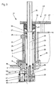
- Fig. 1 eine erfindungsgemäße Ein- oder Auspackmaschine in Seitenansicht;
- Fig. 2 die Ein- oder Auspackmaschine in stirnseitiger Ansicht gemäß 2-2 der
Figur 1; - Fig. 3 eine Überführungseinheit einer Ein- bzw. Auspackmaschine gemäß
Figur 1 und 2 in etwas vergrößerter Darstellung in vertikalem Schnitt; - Fig. 4 die Draufsicht, schematisch einer Ein-oder Auspackmaschine gemäß
Figur 1 bis 5 - Fig. 5 ein Bewegungsschema der Überführungseinheiten und Greifer- und Trägerköpfe in einer Ausführungsform nach
Figur 4 der erfindungsgemäßen Ein- oder Auspackmaschine; - Fig. 6 ein Schaubild der in der Ausführungsform nach
Figur 4 und 5 am Greifer- und Trägerkopf herrschenden Geschwindigkeits- und Beschleunigungsverhältnisse; - Fig. 7 das Bewegungsschema der Überführungseinheiten und Greifer- und Trägerköpfe der Ein- oder Auspackmaschine in abgewandelter Ausführungsform für gleichsinnigen Umlauf der Schwenkarme und Überführungseinheiten.
- Fig. 8 ein Schaubild für die an dem Greifer- und Trägerkopf herrschenden Geschwindigkeits- und Beschleunigungsverhältnisse in einer Ausführungsform der Ein- oder Auspackmaschine gemäß Figur 7.
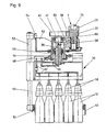
- Fig. 9 eine Greif- und Ausrichteinrichtung für den jeweiligen Greifer- und Trägerkopf.
- 1 shows a packing or unpacking machine according to the invention in a side view;
- Figure 2 shows the packing or unpacking machine in an end view according to 2-2 of Figure 1.
- 3 shows a transfer unit of a packing or unpacking machine according to FIGS. 1 and 2 in a somewhat enlarged illustration in vertical section;
- 4 shows the top view, schematically of a packing or unpacking machine according to FIGS. 1 to 5
- 5 shows a movement diagram of the transfer units and gripper and carrier heads in an embodiment according to FIG. 4 of the packing or unpacking machine according to the invention;
- 6 shows a diagram of the speed and acceleration conditions prevailing on the gripper and carrier head in the embodiment according to FIGS. 4 and 5;
- Fig. 7 shows the movement diagram of the transfer units and gripper and carrier heads of the packing or unpacking machine in a modified embodiment for rotating the swivel arms and transfer units in the same direction.
- 8 shows a diagram for the speed and acceleration conditions prevailing on the gripper and carrier head in an embodiment of the packing or unpacking machine according to FIG. 7.
- Fig. 9 shows a gripping and aligning device for the respective gripper and carrier head.
In den dargestellten Ausführungsbeispielen weist die Ein- oder Auspackmaschine einen torartigen Maschinenrahmen 11 auf, durch den parallel zueinander eine Förderbahn 12 für Artikel, nämlich Flaschen 13, und eine Förderbahn 14 für Gebinde, nämlich Flaschenkästen 15, hindurchgeführt sind. Der Maschinenrahmen 11 trägt an seinem oberen Teil ein Maschinengehäuse 16, in welchem eine Anzahl von beispielsweise sechs Überführungseinheiten 17 mit an heb- und senkbaren Trägern 1 gehaltenen Greifer- und Trägerköpfen 30 für Ausführung einer Hauptumlaufbewegung auf einer Kreisbahn K geführt und mit entsprechenden Antriebseinrichtungen verbunden sind. Diese werden auch zum Antrieb einer ebenfalls im Maschinengehäuse 16 vorgesehenen Bewegungseinrichtung herangezogen, die zur Erzeugung einer die Hauptumlaufbewegung der Überführungseinheiten 17 bzw. heb- und senkbaren Träger 1 überlagernden Relativbewegung für die Greifer- und Trägerköpfe 30 gegenüber den heb- und senkbaren Trägern 1 dient. Die Antriebsbewegung wird in diesem Beispiel von einer im unteren Teil zwischen dem Maschinenrahmen 11 angebrachten Antriebsvorrichtung 18 abgenommen und über eine vertikale Gelenkwelle 19 übertragen. Die Antriebsvorrichtung 18 ist zugleich zum Antrieb der Förderbahn 12 zum Zuführen der Flaschen 13 und zum Antrieb der die leeren Flaschenkästen 15 zuführenden und die gefüllten Flaschenkästen 15 abführenden, gegenüber der Bahnebene der Förderbahn 12 tiefer liegend angeordneten Förderbahn 14 vorgesehen.In the exemplary embodiments shown, the packing or unpacking machine has a gate-
Die Überführungseinheiten 17 sind dabei unter Einhaltung eines gleichmäßigen Teilungsabstandes auf einer Ringplatte 2 eines mit einer Kugeldrehverbindung 3 im Maschinengehäuse 16 drehbar gelagerten topfförmigen Drehtisches 20 angebracht, dessen am umlaufenden Lagerteil der Kugeldrehverbindung 3 ausgebildeter Zahnkranz 4 unter Zwischenschaltung eines Zahnrades 5 über ein mittels der Gelenkwelle 19 angetriebenes Zahnrad 21 in kontinuierliche Drehbewegung versetzt wird, wodurch den Überführungseinheiten 17 und somit deren heb-und senkbaren Trägern 1 eine kontinuierliche Umlaufbewegung auf der Kreisbahn K erteilt wird.The
Wie Figur 3 zeigt, weist jede Überführungseinheit 17 ein äußeres vorzugsweise zylindrisches Gehäuse 22 auf, das in die Ringplatte 2 des Drehtisches 20 fest eingesetzt ist. Innerhalb dieses äußeren Gehäuses 22 ist ein inneres Führungsgehäuse 23 axial verschiebbar gelagert. Dieses Führungsgehäuse 23 nimmt eine vertikale Hauptwelle 24 auf, wobei die Achse dieser Hauptwelle 24 zugleich die auf der Kreisbahn K (vergl. Figuren 5 und 7) wandernde Vertikalachse 26 der Überführungseinheit 17 bzw. des heb- und senkbaren Trägers 1 bildet. Im oberen Teil enthält das Führungsgehäuse 23 eine axial und radial wirksame Lagerung 27 für die Hauptwelle 24. Unterhalb dieser Lagerung 27 ist seitlich in das Führungsgehäuse 23 eine Steuerrolle 28 angesetzt, die zur Erzeugung der Heb- und Senkbewegungen für den im wesentlichen aus dem Führungsgehäuse 23 und der Hauptwelle 24 bestehenden den Greifer- und Trägerkopf 30 haltenden heb-und senkbaren Träger 1 auf einer dem feststehenden Teil des Maschinengehäuses 16 zugeordneten Steuerbahn 29 so umläuft, wie sie in Figur 1 gestrichelt und in den Fig. 6 und 8 strichpunktartig angedeutet und in der Weise ausgebildet ist, daß die mittels der Förderbahn 12 in einer von einer Flaschenkolonne abgeteilten Gruppe angeförderten Flaschen 13 sicher aufgenommen und danach ebenso sicher an den von der Förderbahn 14 der Flaschengruppe zugeteilten Flaschenkasten 15 eingesetzt werden, wobei aber auch sichergestellt ist, daß der jeweils gefüllte Flaschenkasten 15 unbehindert durch den Greifer- und Trägerkopf 30 mit der Förderbahn 14 abtransportiert wird. Der am Führungsgehäuse 23 befestigte Zapfen 31 der Steuerrolle 28 greift durch einen vertikalen Schlitz 32 im äußeren Gehäuse 22, so daß das Führungsgehäuse 23 gegen Verdrehen innerhalb des äußeren Gehäuses 22 und damit auch gegenüber der Ringplatte 2 des Drehtisches 20 gesichert ist. Am unteren Ende des des Führungsgehäuses 23 ist ein Sonnenrad 33 ausgebildet.As FIG. 3 shows, each
Oberhalb eines sich auf die Axial-Radial-Lagerung 27 abstützenden Bundes 34 ist der Wellenbereich 35 der Hauptwelle 24 in der Art einer Vielkeilwelle ausgeführt und in einer dieser angepaßten Nabe eines Umlaufrades 36 axial verschiebbar geführt, wobei dieses Umlaufrad 36 mittels Radial-Wälzlagern 37 im oberen Ende des äußeren Gehäuses 22 drehbar gehalten ist. Auf das untere Ende der Hauptwelle 24 ist ein Schwenkarm 38 fest aufgesetzt, in welchem ein im Sonnenrad 33 kämmendes Zwischenrad 39 (vergl. Figuren 3, 5 und 7) gelagert ist, in dem ein Planetenrad 40 kämmt. Das Planetenrad 40 bildet zusammen mit dem Schwenkarm 38, dem Sonnenrad 33 und dem Zwischenrad 39 ein weiteres, die Parallelstellung des Greifer- und Trägerkopfes 30 gewährleistendes Umlaufgetriebe UW, das Bestandteil der Antriebseinrichtung der Bewegungseinrichtung zur Erzeugung der überlagernden Relativbewegung ist. Das Planetenrad 40 ist mit einem im Schwenkarm 38 drehbar gelagerten Abtriebzapfen 41 fest verbunden, der vertikal angeordnet ist und an seinem unteren Ende den Greifer-und Trägerkopf 30 träft. Die Drehbewegung des Umlaufrades 36 kann in unterschiedlicher Weise erfolgen. Im Beispiel der Figur 1 und 4 ist innerhalb des Maschinengehäuses 16 ein zentrales, feststehendes Zahnrad 42 angeordnet, das auf einem in der oberen kreisförmigen Platte 6 des Drehtisches 20 gelagerten Zapfen 7 befestigt ist. Dieser Zapfen 7 trägt mit seinem über das feststehende Zahnrad 42 nach oben herausgeführten Ende einen üblichen an eine Druckluftquelle angeschlossenen Verteiler 8 für die Versorgung der Greifer- und Trägerköpfe 30 mit Druckluft und ist mittels eines oberhalb des Verteilers 8 angreifenden Armes 9 mit dem feststehenden Teil des Maschinengehäuses 16 so verbunden, daß das feststehende Zahnrad 42 und der ruhende Teil des Verteilers 8 gegen Verdrehung gesichert sind und somit bei Umlauf des Drehtisches 20 feststehen. Für jedes Umlaufrad 36 einer Überführungseinheit 17 ist ein mit dem feststehenden Zahnrad 42 kämmendes Zwischenrad 43 vorgesehen, wobei feststehendes Zahnrad 42, die Umlaufräder 36 und die Zwischenräder 43 sowie der Drehtisch 20 ein der Antriebseinrichtung der Bewegungseinrichtung zur Erzeugung der überlagernden Relativbewegung zugeordnetes gemeinsames Umlaufgetriebe UG zur Bewegung des Schwenkarme 38 der heb- und senkbaren Träger 1 und somit der Greifer-und Trägerköpfe 30 bilden. Die Übertragungsverhältnisse vom feststehenden Zahnrad 42 auf das Umlaufrad 36 sind dabei so getroffen, daß das Umlaufrad 36 bei jedem Umlauf um das Zahnrad 42 eine Umdrehung entgegen der Umlaufrichtung der Überführungseinheiten 17 ausführt. Der Schwenkarm 38 führt somit eine Umdrehung gegensinnig (Figur 4 bis 6) oder gleichsinnig (Fig. 7 und 8) zum Umlauf der Uberführungseinheit 17 aus, so daß er ausgehend von einer bezüglich der vertikalen Zentralachse 50 radial ausgestreckten Stellung bei 0°, s. Figur 5 und 7 nach 90° Umlaufweg der Uberführungseinheit 17 in eine radial einwärts gerichtete Stellung geschwenkt ist. Bei weiteren 90° Umlaufweg hat sich der Schwenkarm 38 in die radial nach außen gerichtete Stellung, nach weiteren 90° Umlaufweg in die radial einwärts gerichtete Stellung und von dort wieder nach 90° Umlaufweg in die ursprüngliche radial auswärtsgerichtete Stellung bewegt. Diese auch aus Fig. 4 hervorgehende Schwenkbewegung verläuft in der Umlaufrichtung 47 entgegengesetztem Sinne. Es ergibt sich hierdurch eine im wesentlichen elliptische Gesamtumlaufbahn 49 für den Abtriebzapfen 41 bzw. für alle Abtriebzapfen 41 der Bewegungseinrichtung um die vertikale Zentralachse 50 herum, wobei durch die vorstehend beschriebene Ausbildung des weiteren Umlaufgetriebes UW sichergestellt ist, daß der Abtriebzapfen 41 im Schwenkarm 38 und somit der von ihm getragene Greifer- und Trägerkopf 30 eine der Umlaufbewegung der Überführungseinheit 17 entgegengesetzte Umdrehung ausführt, um auf diese Weise in jeder Stellung der Überführungseinheit 17 gleiche relative Drehstellung bzw. Flucht des Greifer- und Trägerkopfes 30 bezüglich Förderbahnen 12 und 14 bzw. zu deren Mittelachsen MA und MG einzuhalten. Bei diesem Ausführungsbeispiel ist zum Erreichen einer ausreichend langen Zeit zur Aufnahme der Gruppen von Flaschen 13 bzw. zum Absetzen der Gruppen von Flaschen 13 in die Flaschenkasten 15 für eine Bewegung der Greifer- und Trägerköpfe 30 in Transportrichtung der Förderbänder 12, 14 vorgesehen, daß sowohl zwischen der großen Achse und der Mittelachse MA des Förderbandes 12 als auch zwischen der großen Achse und der Mittelachse MG des Förderbandes 14 ein Abstand besteht, der kleiner als der Radius des kleinen Kreises der elliptischen Gesamtumlaufbahn ist, wobei der Abstand zwischen der großen Achse und der Mittelachse MA des Förderbandes 12 größer ist als der Abstand zwischen der großen Achse und der Mittelachse MG des Förderbandes 14. Es kann aber auch der Abstand gleich groß sein, wenn z. B. die Förderbänder 12, 14 gleiche Höhenlage aufweisen.Above a
Die Ausführungsform nach Figur 7 bezieht sich auf eine für gleichsinnigen Umlauf von Schwenkarm 38 und Überführungseinheit 17 ausgelegtes gemeinsames Umlaufgetriebe UG. Wie in dieser Figur 7 angedeutet, erfolgt bei dieser Ausführungsform der Antrieb der Hauptwelle 24 mittels eines mit einem feststehenden Zahnrad 44 unmittelbar kämmenden Umlaufrades 43' und eines schlupflosen Triebes, beispielsweise eines Zahnriementriebes, wozu dem Antriebsrad 43' eine Zahnriemenscheibe 36' zugeordnet und das mit der Hauptwelle 24 im Eingriff stehende Umlaufrad 36 durch eine Zahnriemenscheibe 36' ersetzt ist sowie ein Zahnriemen 46 als Kraftübertragungsmittel vorgesehen ist. In jedem Fall wird jedoch in dieser Ausführungsform einer der Umlaufbewegung der Überführungseinheit 17 entsprechend dem Pfeil 47 gleichsinnige Drehbewegung an der Zahnriemenscheibe 36' und folglich an der Hauptwelle 24 erzeugt, während die Überführungseinheit 17 einmal um die vertikale Zentralachse 50 herumläuft. Durch die Gleichsinnigkeit der Umlaufbewegung der Überführungseinheit 17 bzw. des ihr zugeordneten heb- und senkbaren Trägers 1 mit der Drehbewegung der Zahnriemenscheibe 36' ergibt sich eine in Figur 7 erkennbare ellipsenähnliche Gesamtumlaufbahn, die eine Zykloidenbahn 48 ist und sich gegenüber der in Figure 5 gezeigten, der Ellipsenform entsprechenden Umlaufbahn 49 an ihren zu den Förderbahnen 12 und 14 bzw. zu deren Mittelachsen MA und MG parallel verlaufenden Abschnitten etwas stärker einer geradlinigen Führung nähert, aber insgesamt noch einer Ellipsenbahn angenähert ist.The embodiment according to FIG. 7 relates to a common epicyclic gear UG designed for rotating the
Der Vergleich der Figuren 6 und 8 zeigt, daß in beiden Ausführungsformen die Vorschubgeschwindigkeit des Greifer- und Trägerkopfes 30 auf seiner Bewegungsbahn 48 bzw. 49 in Abhängigkeit von der augenblicklichen Winkelstellung der Uberführungseinheit 17 im Sinne einer Sinuskurve schwankt. Auch die Kurve für die Beschleunigung des Greifer- und Trägerkopfes 30 ist stetig. Dies bedeutet, daß der gesamte Bewegungsablauf des Greifer- und Trägerkopfes 30 auf seiner Umlaufbahn 48 bzw. 49 stetig und stoßfrei ist. Die geringen Unterschiede zwischen den in Figur 6 für die Ausführungsform nach Figur 4 bis 6 und den in Figur 8 für die Ausführungsform nach Figur 7 wiedergegebenen Kurven ist gegenüber diesem grundsätzlichen Betriebsverhalten unbedeutend.The comparison of FIGS. 6 and 8 shows that in both embodiments the feed speed of the gripper and
Wie aus Figur 1, 2 und 9 ersichtlich, ist in den dargestellten Beispielen jeder mit einer den aufzunehmenden Flaschen 13 entsprechenden Anzahl von üblichen Greiferelementen 58 versehene Greifer-und Trägerkopf 30 mit einer heb- und senkbaren, zusätzlichen Greif- und Ausrichteinrichtung 51 ausgestattet, die einen beim Absenken über den Öffnungsrand des jeweiligen Gebindes bzw. Flaschenkastens 15 greifenden Zentrierrahmen 52 aufweist. Dieser Zentrierrahmen 52 ist an einem Führungsstangenpaar 53 angebracht, das an seinem Führungslager am Greifer- und Trägerkopf 30 aufgehängt ist und ein Führungselement 54 aufweist, das ein Gleitstück oder eine Laufrolle sein kann. Das Führungselement 54 bildet ein Steuerelement, das wie aus Fig. 1 und 2 hervorgeht, über am Maschinenrahmen 11 und Maschinenkasten 16 gehaltene stationäre Steuerführungsbahnen 56, 57 oder, wie Fig. 9 zeigt, auf einer der jeweiligen Greif- und Ausrichteinrichtung 51 an dem den Greifer- und Trägerkopf 30 tragenden Schwenkarm 38 geordneten umlaufenden Topfkurve 62 läuft, um den jeweiligen Zentrierrahmen 52 im Eingangsbereich der Förderbahn 14 über einen dort bereitgestellten Flaschenkasten 15 zu dessen Zentrierung zum Greifer- und Trägerkopf 30 abzusenken und den Flaschenkasten 15 nach Übergabe der Flaschen 13 am Ausgangsbereich der Förderbahn 14 wieder freizugeben. Vor dem Bereich der Förderbahn 12 werden die Zentrierrahmen 52 der Überführungseinheiten 17 soweit angehoben, daß ohne Behinderung der aufzunehmenden Gruppe aus Flaschen 13 die eigentlichen Greiferelemente 58 auf die Flaschen 13 aufgesetzt werden können. Am Ausgangsbereich der Förderbahn 12 , also nach Erfassen der Gruppe aus Flaschen 13 mit den Greiferelementen 58 können die Rahmen 52 bereits soweit abgesenkt werden, daß sie den Flaschen 13 beim weiteren Transport zur Führungsbahn 14 einen zusätzlichen Halt bieten. Zum jeweiligen Erfassen der Gruppe aus Flaschen 13 mittels der Greiferelemente 58 werden diese mit Druckluft beaufschlagt, wozu ein auf einem auch die Topfkurve 62 aufnehmenden Ansatz 63 des Schwenkarmes 38 befestigter Nocken 64 ein auf der Oberseite des dem Greifer- und Trägerkopf 30 angebrachtes Ventil 65 betätigt, um eine Verbindung von einer an den drehenden Teil des Verteilers 8 angeschlossenen, Druckluft heranführenden Zuleitung 66 zu einer die Greiferelemente 58 miteinander verbindenden Leitung 67 herzustellen; vgl. Fig. 9. Zur jeweiligen Freigabe der Gruppe aus Flaschen 13 wird durch Ablauf des Betätigungselements des Ventils 65 vom umlaufenden Nocken 64 die zum Erfassen der Gruppe von Flaschen 13 zwischen der Zuleitung 66 der Leitung 67 bestehende Verbindung unterbrochen und die Leitung 67 über das Ventil 65 zur Entlüftung der Greiferelemente 58 zur Atmosphäre hin geöffnet.As can be seen from FIGS. 1, 2 and 9, in the examples shown each gripper and
Wie aus Figur 1 ersichtlich, ist im Eingangsbereich der Förderbahn 14 für die Flaschenkästen 15 eine Zuteileinrichtung 59 vorgesehen, die jeweils einen Flaschenkasten 15 für jeden herankommenden, mit Flaschen 13 beladenen Greifer- und Führungskopf 30 bereitstellt.As can be seen from FIG. 1, an
In den dargestellten Beispielen handelt es sich um eine Einpackmaschine, mit der Gruppen aus Flaschen 13 in Flaschenkästen 15 eingesetzt werden. In entsprechender Weise ist auch eine Auspackmaschine auszubilden, mit der Gruppen aus Flaschen 13 aus Flaschenkästen 15 zu entnehmen und auf eine Abtransport-Förderbahn zu stellen sind. Die Transportrichtungen sind dabei im wesentlichen gleich vorzusehen wie sie in Figur 1 durch die Pfeile 60 und 61 angedeutet sind, jedoch wird man bevorzugt die Abtransport-Förderbahn dann auf der in Figur 1 linken Seite weiterführen, während sie nach Figur 1 an der rechten Seite herankommt.In the examples shown, it is a packing machine with which groups of
Anstelle von Flaschen 13 und Flaschenkästen 15 kann eine derartige Ein- und Auspackmaschine auch für das Einpacken oder Auspacken anderer Gruppen von Artikeln in andere Gebinde bzw. aus anderen Gebinden ausgebildet sein.Instead of
Claims (18)
Priority Applications (1)
| Application Number | Priority Date | Filing Date | Title |
|---|---|---|---|
| AT87108697T ATE53362T1 (en) | 1986-06-20 | 1987-06-16 | PACKING OR UNPACKING MACHINE. |
Applications Claiming Priority (2)
| Application Number | Priority Date | Filing Date | Title |
|---|---|---|---|
| DE3620717 | 1986-06-20 | ||
| DE19863620717 DE3620717A1 (en) | 1986-06-20 | 1986-06-20 | PACKING OR UNPACKING MACHINE |
Publications (3)
| Publication Number | Publication Date |
|---|---|
| EP0251032A2 EP0251032A2 (en) | 1988-01-07 |
| EP0251032A3 EP0251032A3 (en) | 1988-11-09 |
| EP0251032B1 true EP0251032B1 (en) | 1990-06-06 |
Family
ID=6303347
Family Applications (1)
| Application Number | Title | Priority Date | Filing Date |
|---|---|---|---|
| EP87108697A Expired - Lifetime EP0251032B1 (en) | 1986-06-20 | 1987-06-16 | Packing or unpacking machine |
Country Status (7)
| Country | Link |
|---|---|
| US (1) | US4793762A (en) |
| EP (1) | EP0251032B1 (en) |
| JP (1) | JPH07110655B2 (en) |
| AT (1) | ATE53362T1 (en) |
| BR (1) | BR8703080A (en) |
| DE (2) | DE3620717A1 (en) |
| ES (1) | ES2015921B3 (en) |
Cited By (1)
| Publication number | Priority date | Publication date | Assignee | Title |
|---|---|---|---|---|
| DE4216721A1 (en) * | 1992-05-20 | 1993-11-25 | Kettner Verpackungsmaschf | Packing system for moving bottles and cans in and out of crates - has conveyor system for crates following circulating path of grippers which pick up and put down bottles. |
Families Citing this family (21)
| Publication number | Priority date | Publication date | Assignee | Title |
|---|---|---|---|---|
| DK163118C (en) * | 1989-10-19 | 1992-06-22 | Sanovo Eng As | FOOD TRANSMISSION EQUIPMENT |
| DE9101063U1 (en) * | 1991-01-31 | 1991-04-18 | Rico-Maschinenbau Max Appel KG, 7080 Aalen | Gripping device for bottles or similar containers to be placed together in a box or similar or to be removed from it |
| DE4216671C2 (en) * | 1992-03-11 | 1996-04-25 | Kettner Verpackungsmaschf | Device for packing / unpacking items such as bottles, glasses, cans and the like in or out of containers |
| DE4243008C1 (en) * | 1992-12-19 | 1994-01-20 | Kronseder Maschf Krones | Packing machine for bottles - simultaneously packs or unpacks bottles in or out of cartons or boxes and has conveyor passing horizontally through machine carrying empty containers or those to be unpacked |
| DE4243010C1 (en) * | 1992-12-19 | 1994-05-26 | Kronseder Maschf Krones | Packing machine |
| US5371995A (en) * | 1993-05-20 | 1994-12-13 | H. J. Langen & Sons, Inc. | Hesitating carton loading machine |
| IT1264223B1 (en) * | 1993-09-23 | 1996-09-23 | Alsim S R L | CONTINUOUS MACHINE FOR EXTRACTING AND INSERTING GROUPS OF BOTTLES INTO CRATES WITH CONTINUOUS MOVEMENT. |
| DE19700150A1 (en) * | 1997-01-06 | 1998-07-09 | Focke & Co | Device for filling cardboard boxes |
| DE19913637C1 (en) * | 1999-03-25 | 2000-09-21 | Bell & Howell Co | Device for handling sheet-shaped objects |
| US6389328B1 (en) * | 1999-09-13 | 2002-05-14 | Nippon Crescent Co., Ltd. | Method of and apparatus for attracting and conveying conveyable objects and process of and system for checking in an eating establishment |
| ITRM20010639A1 (en) * | 2001-10-29 | 2003-04-29 | Stasio Modesto Di | MACHINE FOR PACKAGING ON MORE ORDERED FILES, IN BOX CONTAINERS, OBJECTS FEED ON ONE OR MORE FILES. |
| GB0303813D0 (en) * | 2003-02-19 | 2003-03-26 | Meadwestvaco Packaging Systems | Pick and place assembly for continuously packaging articles |
| EP1723035B1 (en) * | 2004-02-27 | 2012-10-24 | Standard Knapp Inc. | Packaging machine |
| WO2007038311A1 (en) * | 2005-09-23 | 2007-04-05 | Delkor Systems, Inc. | Split package assembly |
| DE102016106360A1 (en) | 2016-04-07 | 2017-10-12 | Krones Aktiengesellschaft | System and method for handling articles such as beverage containers or the like |
| DE102018123193A1 (en) | 2018-09-20 | 2020-03-26 | Krones Aktiengesellschaft | Handling and / or packaging device and method for packaging articles |
| AT522732A1 (en) | 2019-06-17 | 2021-01-15 | Knapp Ag | VERTICAL TRANSFORMER FOR A CONVEYOR |
| CN110422397B (en) * | 2019-07-08 | 2020-12-01 | 安徽海思达机器人有限公司 | Automatic cap taking device for wine box |
| CN110422396B (en) * | 2019-07-08 | 2020-12-01 | 安徽海思达机器人有限公司 | Automatic wine bottle loading and wine box device |
| CN111824531A (en) * | 2020-07-21 | 2020-10-27 | 江苏宇航食品科技有限公司 | Intelligent boxing system for upper bottle and lower bottle of glass feeding bottle |
| DE102021102769A1 (en) | 2021-02-05 | 2022-08-11 | Krones Aktiengesellschaft | Device and method for transporting articles such as beverage containers or the like |
Family Cites Families (15)
| Publication number | Priority date | Publication date | Assignee | Title |
|---|---|---|---|---|
| US1654091A (en) * | 1923-03-03 | 1927-12-27 | Hartford Empire Co | Apparatus for handling glassware |
| US2431320A (en) * | 1944-08-02 | 1947-11-25 | Standard Knapp Corp | Tray unloader |
| US2897988A (en) * | 1954-03-08 | 1959-08-04 | Graham Enock Mfg Company Ltd | Crating and decrating of bottles |
| DE1035559B (en) * | 1956-10-30 | 1958-07-31 | Certus Maschb G M B H | Machine for loading or unloading open bottle crates |
| US2966995A (en) * | 1956-10-30 | 1961-01-03 | Certus Maschb G M B H | Machine for introducing or extracting bottles into or from bottle cases |
| US3185328A (en) * | 1957-06-24 | 1965-05-25 | Remy & Cie E P | Machine for handling objects |
| US3026989A (en) * | 1959-08-17 | 1962-03-27 | Afico Sa | Machine for loading articles from the top and for transferring said articles |
| FR1299695A (en) * | 1961-06-16 | 1962-07-27 | Saint Gobain | Device for handling glass sheets moved by a conveyor |
| DE1298438B (en) * | 1964-12-04 | 1969-06-26 | Enzinger Union Werke Ag | Gripper head for a machine for packing and unpacking bottles in or out of transport boxes or the like. |
| DE1586156A1 (en) * | 1967-11-24 | 1970-08-06 | Kronseder Hermann | Bottle packing machine |
| US4055943A (en) * | 1976-06-09 | 1977-11-01 | Abc Packaging Machine Corporation | Bottle loading machine |
| US4449625A (en) * | 1980-10-01 | 1984-05-22 | Hauni-Werke Korber & Co. Kg. | Apparatus for transporting trays for cigarettes or the like |
| IT1159182B (en) * | 1982-06-23 | 1987-02-25 | Sasib Spa | TRANSFER TRANSFER DEVICE SEQUENCES THE SELF-COMPENSATED IN SPEED TO CONVERT INTO TRANSVERSAL RANGE AN AXIAL CURRENT ROW OF ASTIFORM OBJECTS |
| DE3336766C2 (en) * | 1983-10-10 | 1985-08-14 | Max Kettner Verpackungsmaschinenfabrik GmbH & Co KG, 8000 München | Packing or unpacking machine especially for bottles |
| DE3434009A1 (en) * | 1984-09-15 | 1986-03-27 | Index-Werke Kg Hahn & Tessky, 7300 Esslingen | WORKPIECE HANDLING DEVICE |
-
1986
- 1986-06-20 DE DE19863620717 patent/DE3620717A1/en not_active Withdrawn
-
1987
- 1987-06-16 DE DE8787108697T patent/DE3763051D1/en not_active Expired - Fee Related
- 1987-06-16 ES ES87108697T patent/ES2015921B3/en not_active Expired - Lifetime
- 1987-06-16 AT AT87108697T patent/ATE53362T1/en not_active IP Right Cessation
- 1987-06-16 EP EP87108697A patent/EP0251032B1/en not_active Expired - Lifetime
- 1987-06-19 BR BR8703080A patent/BR8703080A/en not_active IP Right Cessation
- 1987-06-19 JP JP62151552A patent/JPH07110655B2/en not_active Expired - Lifetime
- 1987-06-19 US US07/064,992 patent/US4793762A/en not_active Expired - Fee Related
Cited By (1)
| Publication number | Priority date | Publication date | Assignee | Title |
|---|---|---|---|---|
| DE4216721A1 (en) * | 1992-05-20 | 1993-11-25 | Kettner Verpackungsmaschf | Packing system for moving bottles and cans in and out of crates - has conveyor system for crates following circulating path of grippers which pick up and put down bottles. |
Also Published As
| Publication number | Publication date |
|---|---|
| ATE53362T1 (en) | 1990-06-15 |
| DE3620717A1 (en) | 1987-12-23 |
| JPS6322306A (en) | 1988-01-29 |
| EP0251032A2 (en) | 1988-01-07 |
| ES2015921B3 (en) | 1990-09-16 |
| US4793762A (en) | 1988-12-27 |
| BR8703080A (en) | 1988-03-08 |
| EP0251032A3 (en) | 1988-11-09 |
| DE3763051D1 (en) | 1990-07-12 |
| JPH07110655B2 (en) | 1995-11-29 |
Similar Documents
| Publication | Publication Date | Title |
|---|---|---|
| EP0251032B1 (en) | Packing or unpacking machine | |
| EP0490084B1 (en) | Device for packaging or unpacking containers | |
| EP2032481B1 (en) | Conveyor | |
| DE60022931T2 (en) | Foerdervorrichtung for objects | |
| DE3529071A1 (en) | DEVICE FOR STACKING PACKING UNITS | |
| DE69718153T2 (en) | METHOD AND DEVICE FOR HEATING IN BLOW MOLDING | |
| DE1782649C2 (en) | Device for handling and treating, in particular for rinsing containers | |
| DE2229527A1 (en) | Method and device for joining, filling and closing containers | |
| DE69509167T2 (en) | Form, fill and seal machine, in particular for packaging food | |
| DE3338565A1 (en) | STACKING AND CONVEYING SYSTEM FOR PALLETS | |
| DE1761814C3 (en) | Device for separating and transferring containers stacked one inside the other | |
| DE2424341C3 (en) | Device for unloading or loading pallets with extensive pallet layers or for unloading or loading bottle crates | |
| DE1965394A1 (en) | Behaelterueberfuehrungsvorrichtung | |
| DE3339045A1 (en) | Packaging machine for bottles, for example | |
| DE1152351B (en) | Machine for unloading continuously conveyed, open bottle crates | |
| DE3336766C2 (en) | Packing or unpacking machine especially for bottles | |
| DE3343732C2 (en) | ||
| DE1909295A1 (en) | Transfer device | |
| DE102020122419A1 (en) | Transport device for transporting containers | |
| DE102022127240A1 (en) | Container transport device with a guide device and method for transporting containers | |
| DE4427063C2 (en) | Assortment with swiveling swing arm | |
| DE3347626A1 (en) | Device for the positioning and temporary intermediate storage of articles transported along a track | |
| DE69107368T2 (en) | Device for transferring bottles from a bottle crate to a conveyor system. | |
| DE29707657U1 (en) | Device for the transport of disk-shaped substrates in a vacuum coating system or for their storage | |
| DE3336989A1 (en) | Packing or unpacking machine, especially for bottles |
Legal Events
| Date | Code | Title | Description |
|---|---|---|---|
| PUAI | Public reference made under article 153(3) epc to a published international application that has entered the european phase |
Free format text: ORIGINAL CODE: 0009012 |
|
| AK | Designated contracting states |
Kind code of ref document: A2 Designated state(s): AT BE CH DE ES FR GB IT LI NL SE |
|
| PUAL | Search report despatched |
Free format text: ORIGINAL CODE: 0009013 |
|
| AK | Designated contracting states |
Kind code of ref document: A3 Designated state(s): AT BE CH DE ES FR GB IT LI NL SE |
|
| 17P | Request for examination filed |
Effective date: 19890508 |
|
| 17Q | First examination report despatched |
Effective date: 19891121 |
|
| GRAA | (expected) grant |
Free format text: ORIGINAL CODE: 0009210 |
|
| AK | Designated contracting states |
Kind code of ref document: B1 Designated state(s): AT BE CH DE ES FR GB IT LI NL SE |
|
| REF | Corresponds to: |
Ref document number: 53362 Country of ref document: AT Date of ref document: 19900615 Kind code of ref document: T |
|
| REF | Corresponds to: |
Ref document number: 3763051 Country of ref document: DE Date of ref document: 19900712 |
|
| ITF | It: translation for a ep patent filed | ||
| ET | Fr: translation filed | ||
| GBT | Gb: translation of ep patent filed (gb section 77(6)(a)/1977) | ||
| PLBE | No opposition filed within time limit |
Free format text: ORIGINAL CODE: 0009261 |
|
| STAA | Information on the status of an ep patent application or granted ep patent |
Free format text: STATUS: NO OPPOSITION FILED WITHIN TIME LIMIT |
|
| 26N | No opposition filed | ||
| ITTA | It: last paid annual fee | ||
| EAL | Se: european patent in force in sweden |
Ref document number: 87108697.1 |
|
| PGFP | Annual fee paid to national office [announced via postgrant information from national office to epo] |
Ref country code: SE Payment date: 19950428 Year of fee payment: 9 |
|
| PGFP | Annual fee paid to national office [announced via postgrant information from national office to epo] |
Ref country code: CH Payment date: 19950510 Year of fee payment: 9 |
|
| PGFP | Annual fee paid to national office [announced via postgrant information from national office to epo] |
Ref country code: AT Payment date: 19950523 Year of fee payment: 9 |
|
| PG25 | Lapsed in a contracting state [announced via postgrant information from national office to epo] |
Ref country code: AT Effective date: 19960616 |
|
| PG25 | Lapsed in a contracting state [announced via postgrant information from national office to epo] |
Ref country code: SE Effective date: 19960617 |
|
| PG25 | Lapsed in a contracting state [announced via postgrant information from national office to epo] |
Ref country code: LI Effective date: 19960630 Ref country code: CH Effective date: 19960630 |
|
| PGFP | Annual fee paid to national office [announced via postgrant information from national office to epo] |
Ref country code: BE Payment date: 19960701 Year of fee payment: 10 |
|
| REG | Reference to a national code |
Ref country code: CH Ref legal event code: PL |
|
| EUG | Se: european patent has lapsed |
Ref document number: 87108697.1 |
|
| PG25 | Lapsed in a contracting state [announced via postgrant information from national office to epo] |
Ref country code: BE Effective date: 19970630 |
|
| BERE | Be: lapsed |
Owner name: SEITZ ENZINGER NOLL MASCHINENBAU A.G. Effective date: 19970630 |
|
| PGFP | Annual fee paid to national office [announced via postgrant information from national office to epo] |
Ref country code: DE Payment date: 20010322 Year of fee payment: 15 |
|
| PGFP | Annual fee paid to national office [announced via postgrant information from national office to epo] |
Ref country code: ES Payment date: 20010402 Year of fee payment: 15 |
|
| PGFP | Annual fee paid to national office [announced via postgrant information from national office to epo] |
Ref country code: GB Payment date: 20010615 Year of fee payment: 15 |
|
| PGFP | Annual fee paid to national office [announced via postgrant information from national office to epo] |
Ref country code: FR Payment date: 20010626 Year of fee payment: 15 |
|
| PGFP | Annual fee paid to national office [announced via postgrant information from national office to epo] |
Ref country code: NL Payment date: 20010630 Year of fee payment: 15 |
|
| REG | Reference to a national code |
Ref country code: GB Ref legal event code: IF02 |
|
| PG25 | Lapsed in a contracting state [announced via postgrant information from national office to epo] |
Ref country code: GB Free format text: LAPSE BECAUSE OF NON-PAYMENT OF DUE FEES Effective date: 20020616 |
|
| PG25 | Lapsed in a contracting state [announced via postgrant information from national office to epo] |
Ref country code: ES Free format text: LAPSE BECAUSE OF NON-PAYMENT OF DUE FEES Effective date: 20020617 |
|
| PG25 | Lapsed in a contracting state [announced via postgrant information from national office to epo] |
Ref country code: NL Free format text: LAPSE BECAUSE OF NON-PAYMENT OF DUE FEES Effective date: 20030101 Ref country code: DE Free format text: LAPSE BECAUSE OF NON-PAYMENT OF DUE FEES Effective date: 20030101 |
|
| GBPC | Gb: european patent ceased through non-payment of renewal fee |
Effective date: 20020616 |
|
| PG25 | Lapsed in a contracting state [announced via postgrant information from national office to epo] |
Ref country code: FR Free format text: LAPSE BECAUSE OF NON-PAYMENT OF DUE FEES Effective date: 20030228 |
|
| NLV4 | Nl: lapsed or anulled due to non-payment of the annual fee |
Effective date: 20030101 |
|
| REG | Reference to a national code |
Ref country code: FR Ref legal event code: ST |
|
| REG | Reference to a national code |
Ref country code: ES Ref legal event code: FD2A Effective date: 20030711 |
|
| PG25 | Lapsed in a contracting state [announced via postgrant information from national office to epo] |
Ref country code: IT Free format text: LAPSE BECAUSE OF NON-PAYMENT OF DUE FEES Effective date: 20050616 |