EP0248650B1 - Magnetplattenvorrichtung - Google Patents
Magnetplattenvorrichtung Download PDFInfo
- Publication number
- EP0248650B1 EP0248650B1 EP87304907A EP87304907A EP0248650B1 EP 0248650 B1 EP0248650 B1 EP 0248650B1 EP 87304907 A EP87304907 A EP 87304907A EP 87304907 A EP87304907 A EP 87304907A EP 0248650 B1 EP0248650 B1 EP 0248650B1
- Authority
- EP
- European Patent Office
- Prior art keywords
- magnetic
- head
- disc device
- magnetic disc
- head arm
- Prior art date
- Legal status (The legal status is an assumption and is not a legal conclusion. Google has not performed a legal analysis and makes no representation as to the accuracy of the status listed.)
- Expired - Lifetime
Links
Images


Classifications
-
- G—PHYSICS
- G11—INFORMATION STORAGE
- G11B—INFORMATION STORAGE BASED ON RELATIVE MOVEMENT BETWEEN RECORD CARRIER AND TRANSDUCER
- G11B19/00—Driving, starting, stopping record carriers not specifically of filamentary or web form, or of supports therefor; Control thereof; Control of operating function ; Driving both disc and head
- G11B19/20—Driving; Starting; Stopping; Control thereof
-
- G—PHYSICS
- G11—INFORMATION STORAGE
- G11B—INFORMATION STORAGE BASED ON RELATIVE MOVEMENT BETWEEN RECORD CARRIER AND TRANSDUCER
- G11B33/00—Constructional parts, details or accessories not provided for in the other groups of this subclass
- G11B33/12—Disposition of constructional parts in the apparatus, e.g. of power supply, of modules
- G11B33/121—Disposition of constructional parts in the apparatus, e.g. of power supply, of modules the apparatus comprising a single recording/reproducing device
-
- G—PHYSICS
- G11—INFORMATION STORAGE
- G11B—INFORMATION STORAGE BASED ON RELATIVE MOVEMENT BETWEEN RECORD CARRIER AND TRANSDUCER
- G11B25/00—Apparatus characterised by the shape of record carrier employed but not specific to the method of recording or reproducing, e.g. dictating apparatus; Combinations of such apparatus
- G11B25/04—Apparatus characterised by the shape of record carrier employed but not specific to the method of recording or reproducing, e.g. dictating apparatus; Combinations of such apparatus using flat record carriers, e.g. disc, card
- G11B25/043—Apparatus characterised by the shape of record carrier employed but not specific to the method of recording or reproducing, e.g. dictating apparatus; Combinations of such apparatus using flat record carriers, e.g. disc, card using rotating discs
-
- G—PHYSICS
- G11—INFORMATION STORAGE
- G11B—INFORMATION STORAGE BASED ON RELATIVE MOVEMENT BETWEEN RECORD CARRIER AND TRANSDUCER
- G11B5/00—Recording by magnetisation or demagnetisation of a record carrier; Reproducing by magnetic means; Record carriers therefor
- G11B5/48—Disposition or mounting of heads or head supports relative to record carriers ; arrangements of heads, e.g. for scanning the record carrier to increase the relative speed
- G11B5/4806—Disposition or mounting of heads or head supports relative to record carriers ; arrangements of heads, e.g. for scanning the record carrier to increase the relative speed specially adapted for disk drive assemblies, e.g. assembly prior to operation, hard or flexible disk drives
- G11B5/4853—Constructional details of the electrical connection between head and arm
-
- G—PHYSICS
- G11—INFORMATION STORAGE
- G11B—INFORMATION STORAGE BASED ON RELATIVE MOVEMENT BETWEEN RECORD CARRIER AND TRANSDUCER
- G11B5/00—Recording by magnetisation or demagnetisation of a record carrier; Reproducing by magnetic means; Record carriers therefor
- G11B5/48—Disposition or mounting of heads or head supports relative to record carriers ; arrangements of heads, e.g. for scanning the record carrier to increase the relative speed
- G11B5/4806—Disposition or mounting of heads or head supports relative to record carriers ; arrangements of heads, e.g. for scanning the record carrier to increase the relative speed specially adapted for disk drive assemblies, e.g. assembly prior to operation, hard or flexible disk drives
- G11B5/486—Disposition or mounting of heads or head supports relative to record carriers ; arrangements of heads, e.g. for scanning the record carrier to increase the relative speed specially adapted for disk drive assemblies, e.g. assembly prior to operation, hard or flexible disk drives with provision for mounting or arranging electrical conducting means or circuits on or along the arm assembly
-
- G—PHYSICS
- G11—INFORMATION STORAGE
- G11B—INFORMATION STORAGE BASED ON RELATIVE MOVEMENT BETWEEN RECORD CARRIER AND TRANSDUCER
- G11B5/00—Recording by magnetisation or demagnetisation of a record carrier; Reproducing by magnetic means; Record carriers therefor
- G11B5/48—Disposition or mounting of heads or head supports relative to record carriers ; arrangements of heads, e.g. for scanning the record carrier to increase the relative speed
- G11B5/488—Disposition of heads
- G11B5/4886—Disposition of heads relative to rotating disc
-
- G—PHYSICS
- G11—INFORMATION STORAGE
- G11B—INFORMATION STORAGE BASED ON RELATIVE MOVEMENT BETWEEN RECORD CARRIER AND TRANSDUCER
- G11B5/00—Recording by magnetisation or demagnetisation of a record carrier; Reproducing by magnetic means; Record carriers therefor
- G11B5/48—Disposition or mounting of heads or head supports relative to record carriers ; arrangements of heads, e.g. for scanning the record carrier to increase the relative speed
- G11B5/54—Disposition or mounting of heads or head supports relative to record carriers ; arrangements of heads, e.g. for scanning the record carrier to increase the relative speed with provision for moving the head into or out of its operative position or across tracks
- G11B5/55—Track change, selection or acquisition by displacement of the head
- G11B5/5521—Track change, selection or acquisition by displacement of the head across disk tracks
Definitions
- the present invention relates to a magnetic disc device used as a memory for, for example, a mini-computer or a micro-computer.
- a Winchester type magnetic disc device using hard discs 3.5 inch (89 mm) in diameter has been used as a memory means for, for example, a mini-computer or a micro-computer.
- Such a magnetic disc device should, if possible, have a high memory density without any enlargement of its size, to ensure that it is compatible with other conventional devices.
- a conventional magnetic device typically comprises a record medium on which information data is recorded and a magnetic head for reading the information from that medium.
- the magnetic head is disposed in such a manner that it faces the recording area of the record medium, to transmit information data between the record medium and a read/write device.
- the head When a magnetic disc is used as the magnetic medium, the head is attached to a head arm which carries the head and positions it at a desired track in the recording area of the magnetic disc. Therefore, to achieve an accurate positioning of the head at a high speed, it is necessary to reduce the weight of the head construction, including the head arm, to minimise its inertia.
- the height dimension of a magnetic disc device is commercially standardised and a full-height magnetic disc device is marketed.
- a full height magnetic disc device is described in the European application EP-A-0157017 and comprises a case having a base, a number of magnetic discs, a number of magnetic heads, a head actuator and a motor for driving a spindle of the magnetic discs.
- the head actuator comprises a head arm which is rotatable about a pivot, and the pivot comprises an outer sleeve mounted on a stationary shaft.
- the shaft is supported at both ends providing good stability but requiring additional space thus preventing any significant reduction in the height of the disc device.
- a half-height magnetic disc device has been developed with half the memory capacity to realise a small capacity and size magnetic disc device which is compatible with the full-height magnetic disc device, and advantageous from the standpoint of space saving since the height is a half of that of the full-height magnetic disc device.
- Such a half-height magnetic disc device is described later with reference to Figure 5 of the drawings.
- the capacity of the magnetic disc device is to be increased using an ordinary interface circuit, it is desirable to double the number of the discs it contains, from the standpoint of easy installation of a new magnetic disc device having an increased capacity in place of an old device, since it is easy to exchange an old device with a new one and/or simultaneously use a new device with an old one through an ordinary interface circuit. Therefore, a two-disc magnetic disc device was developed as an improvement on a one-disc magnetic disc device. Subsequently, a magnetic disc device comprising four discs has been developed as an improvement on the two-disc device.
- a disc device comprising:
- a case having a base; a plurality of magnetic discs; a plurality of magnetic heads; a head actuator; a motor for driving a spindle of the magnetic discs; the magnetic discs, the magnetic heads and the head actuator being housed within the case; and the head actuator comprising a head arm which is rotatable about a pivot, and the pivot comprising an outer sleeve mounted on a stationary shaft, is characterised in that a lower inner peripheral edge of the outer sleeve is inclined, and the shaft is supported on a seat which has an inclined periphery corresponding to the inclined peripheral edge of the outer sleeve.
- each of the head arms includes a groove-like lead wire holding means formed along the lead wire path, the lead wire being fitted and held therein.
- the present invention makes it possible to house four discs in a half-height magnetic disc device. This could not be realised by the prior art device, since four discs could not be stacked in the shortened half-height device housing when the device had the prior art structure.
- the present invention provides a magnetic disc device which eliminates unnecessary dead space due to the pivot seat of the head actuator, thus realising a compact device.
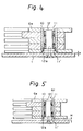
- a conventional magnetic disc device comprises a head actuator having a pivot 6f, as shown in Figure 5.
- the pivot 6f comprises a plurality of head arms 6e which are secured to an outer sleeve 10.
- the outer sleeve 10 is installed on a stationary shaft 12 through two roller bearings 11 and 11′.
- the shaft 12 is disposed on a seat 12a for vertical positioning when secured to the base 1 through a screw.
- the diameter of the seat 12a is approximately the same as that of the outer sleeve 10. Therefore, the space corresponding to the height H of the seat 12a is wasted, thus causing an unnecessary enlarging of the case of the magnetic disc device.
- FIG. 3 is a disassembled perspective view of a magnetic disc device according to the present invention.
- the magnetic disc device comprises: a housing formed by a base 1 and a cover 2; four magnetic discs 4 secured to a spindle 3; eight magnetic heads 5 for magnetic read/write operations at the upper and lower surfaces of each magnetic disc 4; and a head actuator 6 for swinging the magnetic heads 5 in the direction of the arrow AA′ on the magnetic disc surface.
- the head actuator 6 comprises a drive motor 6a, a capstan 6b, a steel belt 6c, a sector 6d, head arms 6e, and a pivot 6f.
- Below the base 1 are disposed a spindle drive motor (not shown), a printed circuit board for driving the spindle drive motor (not shown), and a main printed circuit board 7 mounting a read/write circuit for reading data from and writing data on the magnetic disc.
- the magnetic head 5 is attached to the head arm 6e through a gimbal spring and a load spring 8.
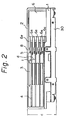
- the magnetic disc device illustrated in Fig. 1 is seen from the upper side thereof, with the cover removed, and Fig. 2 shows a vertical section thereof.
- a bottom plate 30 (Fig. 2) for covering the main printed circuit board 7 is disposed below the base 1 and secured thereto together with the main printed circuit board 7 by screws.
- the height c is the dimension between the lowest surface of the bottom plate 30 and the top surface of the cover 2.
- the gap d between the adjacent magnetic discs 4 is 4.5 mm, and the thickness t of each magnetic disc 4 is 1.27 mm.
- Five head arms 6e are arranged to conduct a seeking motion on both surfaces of the four magnetic discs 4, as shown in Fig. 2.
- the thickness of the two uppermost and lowermost head arms is 2.0 mm, and the thickness of the three intermediate head arms is 2.8 mm.
- the tip of each head arm 6e is thinned to 1.154 mm to attach the load spring 8.
- the gap between the lower surface of the lowermost magnetic disc 4 and the upper surface of the base 1 is 3.5 mm.
- the gap w (Fig. 4) between the lower surface of the lowermost head arm 6e at the pivot portion and the upper surface of the base 1 is 0.5 mm.
- the magnetic discs 4 rotate in the direction of the arrow R (Fig. 1).
- a baffle plate 41 is disposed corresponding to each of the four magnetic discs 4 facing the upper surface thereof, and a filter 2 is incorporated with the baffle plates 41 to capture dust particles on the disc surface.
- the magnetic head 5 is connected to a flexible printed circuit broad 43 (shown by a dash-dot line) bonded behind the head arm 6e through a lead wire 5a′.
- a head IC (preamplifier) 44 is mounted on the flexible printed circuit board 43 behind the head arm 6e.
- the flexible printed circuit board 43 is connected to a connector 45 disposed at a corner of the base 1.
- the flexible printed circuit board 43 is loose and can be folded back and forth within the rear end of the head arm 6e to allow free movement without impeding the swing motion of the head arm 6e.
- the connector 45 is connected to the main printed circuit board 7 (Fig. 5) disposed under the base 1.
- FIG. 4 A pivot structure of the head arm according to the present invention is illustrated in Fig. 4.
- numeral 1 designates a base
- 6e designates a head arm
- 10 designates an outer sleeve
- 11 and 11′ designate roller bearings
- 12 designates a stationary shaft.
- this embodiment of the pivot structure comprises the outer sleeve 10, which supports a plurality of head arms 6e simultaneously, and the stationary shaft 12 which rotatably supports the outer sleeve 10 thereon through two roller bearings 11 and 11′.
- the stationary shaft 12 is placed on a seat 12a having a diameter which is approximately the same as that of the outer sleeve 10, to ensure the verticality of the shaft which is secured to the base 1 by a screw, similar to the prior art structure of Fig. 5.
- a primary feature of this embodiment resides in the structure wherein the inner peripheral edge of the lower end of the outer sleeve 10 is inclined and the outer periphery of the seat 12a of the shaft 12 is also inclined in a direction facing the inner inclined lower end of the outer sleeve 10.
- the seat 12a is arranged to fit into the inclined lower inner edge of the outer sleeve 10, thus eliminating the unnecessary dead space corresponding to the height H of the seat as described with reference to Fig. 5 of the prior art structure. Therefore, it is possible to reduce the height of the magnetic disc device.
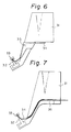
- a prior art magnetic head structure is illustrated in Figure 6.
- a head 33 is supported at an end of a gimbal 32 which is secured to a head arm 31.
- Information data is transmitted between the head and a read/write device through a lead wire 34.
- a springy clip 35 made of plastic is attached to the head arm 31 to hold the lead wire 34 between the head arm 31 and the clip 35 along the head arm side edge.
- the head arm 31 becomes heavy, since the clip 35 is used for holding the lead wire 34, thus opposing the requirement for reducing the weight of the head arm structure. Also, the gap between the discs must be wide enough to dispose the clips 35 therein, which prevents a reduction of the height of the magnetic device.
- a coil lead wire cable arrangement according to the present invention is described hereinafter with reference to Figures 7 and 9.
- Figure 7 is an explanatory view of the principle of the arrangement of the present invention.
- numeral 36 designates a cable holding means comprising a groove formed along the cable pass. The cable 34 is fitted into this groove.
- the cable 34 is fitted and held in the groove of the holding means 36 formed in the head arm 31. Therefore, it is unnecessary to use a special instrument for holding the cable like a clip to hold the cable, thus reducing the weight of the magnetic head structure.
- Figures 8(a) and 8(b) An example of the cable holding arrangement according to the present invention is illustrated in Figures 8(a) and 8(b), wherein the same parts as shown in Figure 7 are designated by the same numerals.
- Figure 8(a) is a plan view of the arrangement and Figure 8(b) is a sectional view along the line AA′ of Figure 8(a).
- a groove 37 is formed as a cable holding means along the cable pass on the head arm.
- Figure 8(b) shows a cross section of the groove 37, which comprises a rectangular recess for receiving the cable 34.
- the cable 34 is held in this groove 37 by press fitting the cable into the groove.
- An adhesive agent may be used to firmly hold the cable 34 within the groove 37.
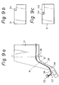
- FIG. 9(a), 9(b) and 9(c) Another example of the cable holding arrangement according to the present invention is illustrated in Figure 9(a), 9(b) and 9(c).
- a step is formed along the cable pass on the head arm 31, as shown in Figure 9(b) which shows a cross section along the line BB′ of the head arm 31 of Figure 9(a).
- a plurality of holder projections 38 are disposed along the step of the cable pass to partly form a groove-like portion, as shown in Figure 9(c) which is a cross section along the line CC′ of the head arm of Figure 9(a).
- the cable 34 is held in this groove-like portion.
- the magnetic head structure according to the present invention comprises a groove as a lead wire holding means formed along the cable pass on the head arm, which makes it unneccesary to use a special cable holding instrument means, thus enabling a reduction of the weight of the magnetic head.
Landscapes
- Supporting Of Heads In Record-Carrier Devices (AREA)
- Moving Of Heads (AREA)
- Adjustment Of The Magnetic Head Position Track Following On Tapes (AREA)
Claims (2)
Applications Claiming Priority (6)
| Application Number | Priority Date | Filing Date | Title |
|---|---|---|---|
| JP85144/86U | 1986-06-04 | ||
| JP1986085144U JPS62202616U (de) | 1986-06-04 | 1986-06-04 | |
| JP1986109459U JPS6316617U (de) | 1986-07-18 | 1986-07-18 | |
| JP109459/86U | 1986-07-18 | ||
| JP1986110030U JPS6316660U (de) | 1986-07-19 | 1986-07-19 | |
| JP110030/86U | 1986-07-19 |
Related Child Applications (1)
| Application Number | Title | Priority Date | Filing Date |
|---|---|---|---|
| EP91200324.1 Division-Into | 1987-06-03 |
Publications (3)
| Publication Number | Publication Date |
|---|---|
| EP0248650A2 EP0248650A2 (de) | 1987-12-09 |
| EP0248650A3 EP0248650A3 (en) | 1988-10-26 |
| EP0248650B1 true EP0248650B1 (de) | 1992-04-22 |
Family
ID=27304778
Family Applications (2)
| Application Number | Title | Priority Date | Filing Date |
|---|---|---|---|
| EP91200324A Expired - Lifetime EP0432145B1 (de) | 1986-06-04 | 1987-06-03 | Magnet-Scheibengerät |
| EP87304907A Expired - Lifetime EP0248650B1 (de) | 1986-06-04 | 1987-06-03 | Magnetplattenvorrichtung |
Family Applications Before (1)
| Application Number | Title | Priority Date | Filing Date |
|---|---|---|---|
| EP91200324A Expired - Lifetime EP0432145B1 (de) | 1986-06-04 | 1987-06-03 | Magnet-Scheibengerät |
Country Status (4)
| Country | Link |
|---|---|
| US (3) | US5060100A (de) |
| EP (2) | EP0432145B1 (de) |
| KR (2) | KR910001715B1 (de) |
| DE (2) | DE3778427D1 (de) |
Families Citing this family (54)
| Publication number | Priority date | Publication date | Assignee | Title |
|---|---|---|---|---|
| US4979063A (en) * | 1986-10-02 | 1990-12-18 | Seagate Technology, Inc. | Design for an actuator arm for a disc drive |
| JPS6412296U (de) * | 1987-07-10 | 1989-01-23 | ||
| US5956213A (en) * | 1988-01-25 | 1999-09-21 | Seagate Technology, Inc. | Latch mechanism for disk drive using magnetic field of actuator magnets |
| US5621582A (en) * | 1988-01-25 | 1997-04-15 | Conner Peripherals, Inc. | Disk drive including a baseplate well for the spin motor |
| US5245486A (en) * | 1989-05-20 | 1993-09-14 | Fujitsu Limited | Disk unit with a side mounted board |
| US5490027A (en) * | 1991-10-28 | 1996-02-06 | Censtor Corp. | Gimbaled micro-head/flexure/conductor assembly and system |
| JP2935129B2 (ja) * | 1990-05-28 | 1999-08-16 | インターナショナル・ビジネス・マシーンズ・コーポレーション | 固定磁気ディスク装置及び関連する装置・方法 |
| WO1992001283A1 (en) * | 1990-07-06 | 1992-01-23 | Conner Peripherals, Inc. | Low height disk drive |
| JP2645606B2 (ja) * | 1990-09-03 | 1997-08-25 | 富士通株式会社 | ロータリーアクチュエータの構造 |
| US5276572A (en) * | 1990-09-19 | 1994-01-04 | Hitachi, Ltd. | Magnetic disk apparatus |
| US5074029A (en) * | 1990-10-02 | 1991-12-24 | International Business Machines Corporation | Method for stringing wire on an actuator arm |
| CA2055060C (en) * | 1990-12-31 | 1996-04-16 | John R. Reidenbach | Rotary actuator for disk drive assemblies |
| KR960001250B1 (ko) * | 1991-06-10 | 1996-01-24 | 후지쓰 가부시끼가이샤 | 자기 디스크드라이브 |
| US5315465A (en) * | 1991-07-12 | 1994-05-24 | Seagate Technology, Inc. | Compliant pivot mechanism for a rotary actuator |
| JPH0574086A (ja) * | 1991-09-12 | 1993-03-26 | Internatl Business Mach Corp <Ibm> | デイスク記憶装置のサスペンシヨンの取付け構造及び取付け方法 |
| KR100274667B1 (ko) * | 1991-11-22 | 2000-12-15 | 윌리암 엘. 허드슨 | 적은 크기의 일정한 토크를 가진 음성코일모터 |
| US5396388A (en) * | 1992-02-27 | 1995-03-07 | Censtor Corp. | Compact, high-speed, rotary actuator and transducer assembly with reduced moment of inertia and mass-balanced structural overlap with drive motor and organizing method for the same |
| EP0582463B1 (de) * | 1992-08-04 | 1998-04-29 | Seagate Technology International | Schwingspulenmotor und Platteneinheit |
| JP2725977B2 (ja) * | 1992-08-28 | 1998-03-11 | インターナショナル・ビジネス・マシーンズ・コーポレイション | 磁気抵抗センサ及びその製造方法、磁気記憶システム |
| US5636086A (en) * | 1993-05-28 | 1997-06-03 | International Business Machines Corporation | Roll insensitive air bearing slider |
| JPH0745060A (ja) * | 1993-07-30 | 1995-02-14 | Citizen Watch Co Ltd | 磁気ディスク装置 |
| DE69407299T2 (de) * | 1993-08-23 | 1998-05-28 | Heath John Stewart | Armlagerung mit rollbewegung für ein plattenlaufwerk |
| KR0135109B1 (ko) * | 1994-04-23 | 1998-04-22 | 김광호 | 하드디스크 드라이브의 가요성 인쇄회로(fpc) 연결장치 |
| JP3199977B2 (ja) | 1995-03-17 | 2001-08-20 | 富士通株式会社 | ディスク装置 |
| JPH097145A (ja) * | 1995-06-15 | 1997-01-10 | Fujitsu Ltd | ディスク装置のアクチュエータアームアセンブリ |
| JP3400248B2 (ja) * | 1995-08-30 | 2003-04-28 | インターナショナル・ビジネス・マシーンズ・コーポレーション | ディスク・ドライブ装置用のヘッド・サスペンションのロード・ビーム |
| US5710680A (en) * | 1995-12-22 | 1998-01-20 | Pc Peripherals Inc. | Magnetic hard disk drive head suspension apparatus |
| US5912787A (en) * | 1996-10-07 | 1999-06-15 | Magnecomp Corp. | Disk drive suspension with minimum wire-induced bias |
| US6011671A (en) * | 1997-04-10 | 2000-01-04 | Seagate Technology, Inc. | Head gimbal assembly for limiting dimple separation for a data storage device |
| US6900962B1 (en) * | 1997-09-05 | 2005-05-31 | Seagate Technology Llc | High performance standard configuration disc drive having smaller-than-standard discs |
| US6288866B1 (en) * | 1999-11-19 | 2001-09-11 | Western Digital Technologies, Inc. | Disk drive including a vibration damping system having a compressible foam and mass damper fixed adjacent to the outer surface of a printed circuit board for reducing noise and vibration |
| US6775104B2 (en) | 2000-09-27 | 2004-08-10 | Seagate Technology Llc | Actuator arm damper with integrated pre-amplifier |
| JP2002170345A (ja) * | 2000-11-29 | 2002-06-14 | Internatl Business Mach Corp <Ibm> | ヘッド・アセンブリ、ディスク・ドライブ装置、ハード・ディスク・ドライブおよびディスク・ドライブ装置の製造方法 |
| US6882501B2 (en) * | 2000-11-30 | 2005-04-19 | Maxtor Corporation | Flow modification for reducing track misregistration in hard disk drives |
| US6762908B2 (en) * | 2001-06-18 | 2004-07-13 | Samsung Electronics Co., Ltd. | Air razor and disk limiter for a hard disk drive |
| US6754046B2 (en) | 2001-09-20 | 2004-06-22 | Seagate Technology Llc | Increased slip force pivot bearing |
| US6754045B2 (en) | 2002-01-03 | 2004-06-22 | Seagate Tech. Llc | Electrical interconnect with a retaining feature for an actuator assembly |
| US6826009B1 (en) * | 2002-08-30 | 2004-11-30 | General Electric Capital Corporation | Disk drive including a filter element disposed along a disk surface for filtering disk rotation induced airflow |
| KR100524981B1 (ko) * | 2003-08-07 | 2005-10-31 | 삼성전자주식회사 | 흡착 필터를 가진 액츄에이터와 이를 구비한 디스크드라이브 |
| US7145753B1 (en) * | 2004-05-15 | 2006-12-05 | Western Digital Technologies, Inc. | Head stack assembly with insulated wiring extending between actuator coil and actuator main body section disposed in lateral wiring protector extending from actuator body |
| US8102621B2 (en) * | 2009-10-15 | 2012-01-24 | Hitachi Global Storage Technologies Netherlands B.V. | Integrated upstream spoiler and particle filter in a hard-disk drive (HDD) |
| US8355220B2 (en) * | 2009-12-14 | 2013-01-15 | HGST Netherlands B.V. | Upstream spoiler with integrated crash stop |
| US10410681B1 (en) * | 2018-07-23 | 2019-09-10 | Seagate Technology Llc | Printed circuit board snap-in mounting |
| TWI856233B (zh) | 2020-01-29 | 2024-09-21 | 美商艾德凡斯化學公司 | 胺基酸界面活性劑 |
| TWI786519B (zh) | 2020-01-29 | 2022-12-11 | 美商艾德凡斯化學公司 | 胺基酸界面活性劑 |
| JP2023517666A (ja) | 2020-03-11 | 2023-04-26 | アドバンシックス・レジンズ・アンド・ケミカルズ・リミテッド・ライアビリティ・カンパニー | 農業用製品のための界面活性剤 |
| KR102763089B1 (ko) | 2020-03-11 | 2025-02-04 | 어드밴식스 레진즈 앤드 케미컬즈 엘엘씨 | 개인 관리 및 화장품 제품을 위한 계면활성제 |
| EP4118174A1 (de) | 2020-03-11 | 2023-01-18 | AdvanSix Resins & Chemicals LLC | Tenside für reinigungsmittel |
| MX2022011056A (es) | 2020-03-11 | 2022-12-06 | Advansix Resins & Chemicals Llc | Tensioactivos para productos electronicos. |
| MX2022011093A (es) | 2020-03-11 | 2022-11-10 | Advansix Resins & Chemicals Llc | Tensioactivos para tintas, pinturas y adhesivos. |
| JP2023517664A (ja) | 2020-03-11 | 2023-04-26 | アドバンシックス・レジンズ・アンド・ケミカルズ・リミテッド・ライアビリティ・カンパニー | 油及びガス生産のための界面活性剤 |
| US11423931B2 (en) * | 2020-11-14 | 2022-08-23 | Western Digital Technologies, Inc. | Data storage device interleave driving secondary actuators |
| US11482246B2 (en) * | 2021-02-15 | 2022-10-25 | Western Digital Technologies, Inc. | Data storage device independently driving outer and inner fine actuators |
| US11482254B2 (en) * | 2021-02-15 | 2022-10-25 | Western Digital Technologies, Inc. | Data storage device independently driving outer and inner fine actuators |
Family Cites Families (29)
| Publication number | Priority date | Publication date | Assignee | Title |
|---|---|---|---|---|
| US3931641A (en) * | 1974-08-22 | 1976-01-06 | International Business Machines Corporation | Transducer suspension mount apparatus |
| JPS5149012A (ja) * | 1974-10-24 | 1976-04-27 | Suwa Seikosha Kk | Jikikiokusochi |
| US4161004A (en) * | 1977-04-05 | 1979-07-10 | Shugart Associates | Head positioning mechanism for recording/playback machine |
| DE2723140C2 (de) * | 1977-05-23 | 1986-06-12 | Basf Ag, 6700 Ludwigshafen | Vorrichtung zum Positionieren von Gegenständen |
| FR2420809A1 (fr) * | 1978-03-24 | 1979-10-19 | Cii Honeywell Bull | Dispositif de lecture-ecriture d'un support d'information a prise de vol par rampe a faible charge |
| US4164766A (en) * | 1978-04-24 | 1979-08-14 | Data General Corporation | Disc memory apparatus magnetic head carriage manual control |
| US4194225A (en) * | 1978-06-06 | 1980-03-18 | International Memories, Inc. | Housing for disk drive unit |
| USRE32702F1 (en) * | 1978-11-03 | 1991-03-05 | Brushless d.c.motor assembly | |
| US4352134A (en) * | 1979-11-19 | 1982-09-28 | International Business Machines Corporation | Magnetic head assembly with corrosion resistant conductive wire |
| US4422115A (en) * | 1980-02-29 | 1983-12-20 | Digital Equipment Corporation | Lightweight dual head support assembly for magnetic disk drives |
| US4367502A (en) * | 1980-04-11 | 1983-01-04 | Shugart Technology | Fixed hard disc drive assembly and clean air system |
| EP0060358B1 (de) * | 1981-03-18 | 1984-11-21 | International Business Machines Corporation | Kopftragarm und Kopftragarmzusammenbau für Plattenspeicher |
| JPS57191872A (en) * | 1981-05-20 | 1982-11-25 | Fujitsu Ltd | Magnetic head |
| US4415821A (en) * | 1982-05-10 | 1983-11-15 | Kollmorgen Technologies Corporation | Dynamic magnetic preload bearing structure for a linear motor |
| AT378301B (de) * | 1983-06-17 | 1985-07-25 | Philips Nv | System zum wiedergeben von auf einem magnetband gespeicherten signalen |
| JPS6035319A (ja) * | 1983-08-04 | 1985-02-23 | Fuji Photo Film Co Ltd | 回転磁気記録体トラッキング装置 |
| JPS60133569A (ja) * | 1983-12-21 | 1985-07-16 | Hitachi Ltd | 磁気デイスク装置 |
| JPS60138789A (ja) * | 1983-12-27 | 1985-07-23 | Toshiba Corp | 磁気ヘツドの組立方法 |
| US4568988A (en) * | 1984-02-22 | 1986-02-04 | Rodime Plc | Micro hard-disk drive system |
| DE3412231A1 (de) * | 1984-04-02 | 1985-10-03 | Nixdorf Computer Ag, 4790 Paderborn | Traegeranordnung fuer magnetkoepfe eines magnetplattenlaufwerkes |
| JPS6166216A (ja) * | 1984-09-07 | 1986-04-05 | Hitachi Ltd | 磁気ヘツド |
| JPS6190079U (de) * | 1984-11-16 | 1986-06-11 | ||
| US4647997A (en) * | 1985-04-29 | 1987-03-03 | Plus Development Corporation | Aerodynamic latch for disk file actuator |
| DE8519878U1 (de) * | 1985-07-10 | 1985-10-17 | Basf Ag, 6700 Ludwigshafen | Vorrichtung zum Positionieren von Gegenständen geringer Masse insbesondere von mindestens einem Magnetkopf, in bezug auf einen zweiten Gegenstand, insbesondere auf mindestens eines Magnetplatte |
| US4707754A (en) * | 1985-08-07 | 1987-11-17 | Apple Computer, Inc. | Voice coil balanced actuator |
| US5023733A (en) * | 1985-12-16 | 1991-06-11 | Seiko Epson Corporation | Head positioning control for a spindle motor disk drive |
| US4716478A (en) * | 1986-02-14 | 1987-12-29 | Hewlett-Packard Company | Two point attachment with single point clamping for connecting the arm stack to the actuator member in a disc memory drive |
| JPH0424552Y2 (de) * | 1986-07-18 | 1992-06-10 | ||
| US4805055A (en) * | 1986-11-24 | 1989-02-14 | Maxtor | Winchester disc drive actuator structure |
-
1987
- 1987-06-03 EP EP91200324A patent/EP0432145B1/de not_active Expired - Lifetime
- 1987-06-03 EP EP87304907A patent/EP0248650B1/de not_active Expired - Lifetime
- 1987-06-03 DE DE8787304907T patent/DE3778427D1/de not_active Expired - Lifetime
- 1987-06-03 DE DE3789391T patent/DE3789391T2/de not_active Expired - Fee Related
- 1987-06-04 KR KR1019870005657A patent/KR910001715B1/ko not_active Expired
- 1987-06-04 KR KR870005657A patent/KR880000947A/ko active Granted
-
1990
- 1990-01-11 US US07/463,838 patent/US5060100A/en not_active Expired - Fee Related
-
1994
- 1994-02-17 US US08/197,541 patent/US5418666A/en not_active Expired - Lifetime
-
1995
- 1995-01-04 US US08/368,640 patent/US5646800A/en not_active Expired - Lifetime
Also Published As
| Publication number | Publication date |
|---|---|
| KR910001715B1 (ko) | 1991-03-19 |
| DE3778427D1 (de) | 1992-05-27 |
| EP0432145A3 (en) | 1992-05-06 |
| DE3789391T2 (de) | 1994-06-23 |
| EP0248650A3 (en) | 1988-10-26 |
| EP0432145A2 (de) | 1991-06-12 |
| DE3789391D1 (de) | 1994-04-21 |
| KR880000947A (ko) | 1988-03-30 |
| US5060100A (en) | 1991-10-22 |
| EP0432145B1 (de) | 1994-03-16 |
| EP0248650A2 (de) | 1987-12-09 |
| US5418666A (en) | 1995-05-23 |
| US5646800A (en) | 1997-07-08 |
Similar Documents
| Publication | Publication Date | Title |
|---|---|---|
| EP0248650B1 (de) | Magnetplattenvorrichtung | |
| EP0556302B1 (de) | Anordnung von flachspulantrieben für mehrere magnetköpfe in plattenspeichern | |
| US4890176A (en) | Crash stop and magnetic latch for a voice coil actuator | |
| US5224000A (en) | Crash stop and magnetic latch for a voice coil actuator | |
| US5343345A (en) | Magnetic disk storage apparatus with multiple sets of actuator arms for read/write operations at different circumferential locations within the disk stack | |
| US4814913A (en) | Compact magnetic disc assembly | |
| US4947274A (en) | Resiliently mounted crash stop and magnetic latch for a voice coil actuator | |
| US8305707B2 (en) | Coupling structure using stud | |
| EP0556287B1 (de) | Architektur für hochleistungsplattenantrieb | |
| US5193037A (en) | Compact disk drive for use with laptop computer | |
| US6243228B1 (en) | Information storage and retrieval device | |
| US4924337A (en) | Disk drive servo shield | |
| US20050057848A1 (en) | Magnetic disk space | |
| US20050135001A1 (en) | Magnetic recording device | |
| JPH0346172A (ja) | ハードディスク駆動装置の一体形ヘッド固定組立体 | |
| JPH021749Y2 (de) | ||
| JPS61151891A (ja) | デイスク装置回路基板実装方法 | |
| JPH052844A (ja) | 磁気デイスク装置 | |
| JPS6292111A (ja) | デイスク記憶装置 | |
| JPH01173376A (ja) | 磁気ディスク装置 | |
| JP2005092909A (ja) | ヘッド・ジンバル・アセンブリ、ヘッド・スタック・アセンブリ及び磁気ディスク装置 | |
| JP2001155457A (ja) | ヘッド支持機構およびこれを用いた情報記録再生装置 | |
| JPH06295544A (ja) | 磁気ヘッドアッセンブリ、その磁気ヘッドアッセンブリを用いた磁気ディスク装置 | |
| JPH06295561A (ja) | 磁気ディスク装置 | |
| JPH05314749A (ja) | 情報記録装置 |
Legal Events
| Date | Code | Title | Description |
|---|---|---|---|
| PUAI | Public reference made under article 153(3) epc to a published international application that has entered the european phase |
Free format text: ORIGINAL CODE: 0009012 |
|
| AK | Designated contracting states |
Kind code of ref document: A2 Designated state(s): DE GB IT |
|
| PUAL | Search report despatched |
Free format text: ORIGINAL CODE: 0009013 |
|
| AK | Designated contracting states |
Kind code of ref document: A3 Designated state(s): DE GB IT |
|
| 17P | Request for examination filed |
Effective date: 19890413 |
|
| 17Q | First examination report despatched |
Effective date: 19901012 |
|
| ITF | It: translation for a ep patent filed | ||
| GRAA | (expected) grant |
Free format text: ORIGINAL CODE: 0009210 |
|
| AK | Designated contracting states |
Kind code of ref document: B1 Designated state(s): DE GB IT |
|
| XX | Miscellaneous (additional remarks) |
Free format text: TEILANMELDUNG 91200324.1 EINGEREICHT AM 03/06/87. |
|
| REF | Corresponds to: |
Ref document number: 3778427 Country of ref document: DE Date of ref document: 19920527 |
|
| ITTA | It: last paid annual fee | ||
| PLBE | No opposition filed within time limit |
Free format text: ORIGINAL CODE: 0009261 |
|
| STAA | Information on the status of an ep patent application or granted ep patent |
Free format text: STATUS: NO OPPOSITION FILED WITHIN TIME LIMIT |
|
| 26N | No opposition filed | ||
| PGFP | Annual fee paid to national office [announced via postgrant information from national office to epo] |
Ref country code: GB Payment date: 19930521 Year of fee payment: 7 |
|
| PG25 | Lapsed in a contracting state [announced via postgrant information from national office to epo] |
Ref country code: GB Effective date: 19940603 |
|
| PGFP | Annual fee paid to national office [announced via postgrant information from national office to epo] |
Ref country code: DE Payment date: 19940608 Year of fee payment: 8 |
|
| GBPC | Gb: european patent ceased through non-payment of renewal fee |
Effective date: 19940603 |
|
| PG25 | Lapsed in a contracting state [announced via postgrant information from national office to epo] |
Ref country code: DE Effective date: 19960301 |
|
| PG25 | Lapsed in a contracting state [announced via postgrant information from national office to epo] |
Ref country code: IT Free format text: LAPSE BECAUSE OF NON-PAYMENT OF DUE FEES;WARNING: LAPSES OF ITALIAN PATENTS WITH EFFECTIVE DATE BEFORE 2007 MAY HAVE OCCURRED AT ANY TIME BEFORE 2007. THE CORRECT EFFECTIVE DATE MAY BE DIFFERENT FROM THE ONE RECORDED. Effective date: 20050603 |