EP0248411B1 - Druckregler für Kraftstoff - Google Patents
Druckregler für Kraftstoff Download PDFInfo
- Publication number
- EP0248411B1 EP0248411B1 EP87108013A EP87108013A EP0248411B1 EP 0248411 B1 EP0248411 B1 EP 0248411B1 EP 87108013 A EP87108013 A EP 87108013A EP 87108013 A EP87108013 A EP 87108013A EP 0248411 B1 EP0248411 B1 EP 0248411B1
- Authority
- EP
- European Patent Office
- Prior art keywords
- fuel pressure
- diaphragm
- valve seat
- resilient member
- valve
- Prior art date
- Legal status (The legal status is an assumption and is not a legal conclusion. Google has not performed a legal analysis and makes no representation as to the accuracy of the status listed.)
- Expired - Lifetime
Links
Images


Classifications
-
- F—MECHANICAL ENGINEERING; LIGHTING; HEATING; WEAPONS; BLASTING
- F02—COMBUSTION ENGINES; HOT-GAS OR COMBUSTION-PRODUCT ENGINE PLANTS
- F02M—SUPPLYING COMBUSTION ENGINES IN GENERAL WITH COMBUSTIBLE MIXTURES OR CONSTITUENTS THEREOF
- F02M69/00—Low-pressure fuel-injection apparatus ; Apparatus with both continuous and intermittent injection; Apparatus injecting different types of fuel
-
- G—PHYSICS
- G05—CONTROLLING; REGULATING
- G05D—SYSTEMS FOR CONTROLLING OR REGULATING NON-ELECTRIC VARIABLES
- G05D16/00—Control of fluid pressure
- G05D16/14—Control of fluid pressure with auxiliary non-electric power
- G05D16/18—Control of fluid pressure with auxiliary non-electric power derived from an external source
- G05D16/185—Control of fluid pressure with auxiliary non-electric power derived from an external source using membranes within the main valve
-
- F—MECHANICAL ENGINEERING; LIGHTING; HEATING; WEAPONS; BLASTING
- F02—COMBUSTION ENGINES; HOT-GAS OR COMBUSTION-PRODUCT ENGINE PLANTS
- F02D—CONTROLLING COMBUSTION ENGINES
- F02D41/00—Electrical control of supply of combustible mixture or its constituents
- F02D41/02—Circuit arrangements for generating control signals
- F02D41/04—Introducing corrections for particular operating conditions
- F02D41/06—Introducing corrections for particular operating conditions for engine starting or warming up
- F02D41/062—Introducing corrections for particular operating conditions for engine starting or warming up for starting
- F02D41/065—Introducing corrections for particular operating conditions for engine starting or warming up for starting at hot start or restart
-
- F—MECHANICAL ENGINEERING; LIGHTING; HEATING; WEAPONS; BLASTING
- F02—COMBUSTION ENGINES; HOT-GAS OR COMBUSTION-PRODUCT ENGINE PLANTS
- F02M—SUPPLYING COMBUSTION ENGINES IN GENERAL WITH COMBUSTIBLE MIXTURES OR CONSTITUENTS THEREOF
- F02M51/00—Fuel-injection apparatus characterised by being operated electrically
- F02M51/02—Fuel-injection apparatus characterised by being operated electrically specially for low-pressure fuel-injection
-
- F—MECHANICAL ENGINEERING; LIGHTING; HEATING; WEAPONS; BLASTING
- F02—COMBUSTION ENGINES; HOT-GAS OR COMBUSTION-PRODUCT ENGINE PLANTS
- F02M—SUPPLYING COMBUSTION ENGINES IN GENERAL WITH COMBUSTIBLE MIXTURES OR CONSTITUENTS THEREOF
- F02M69/00—Low-pressure fuel-injection apparatus ; Apparatus with both continuous and intermittent injection; Apparatus injecting different types of fuel
- F02M69/16—Low-pressure fuel-injection apparatus ; Apparatus with both continuous and intermittent injection; Apparatus injecting different types of fuel characterised by means for metering continuous fuel flow to injectors or means for varying fuel pressure upstream of continuously or intermittently operated injectors
- F02M69/18—Low-pressure fuel-injection apparatus ; Apparatus with both continuous and intermittent injection; Apparatus injecting different types of fuel characterised by means for metering continuous fuel flow to injectors or means for varying fuel pressure upstream of continuously or intermittently operated injectors the means being metering valves throttling fuel passages to injectors or by-pass valves throttling overflow passages, the metering valves being actuated by a device responsive to the engine working parameters, e.g. engine load, speed, temperature or quantity of air
- F02M69/20—Low-pressure fuel-injection apparatus ; Apparatus with both continuous and intermittent injection; Apparatus injecting different types of fuel characterised by means for metering continuous fuel flow to injectors or means for varying fuel pressure upstream of continuously or intermittently operated injectors the means being metering valves throttling fuel passages to injectors or by-pass valves throttling overflow passages, the metering valves being actuated by a device responsive to the engine working parameters, e.g. engine load, speed, temperature or quantity of air the device being a servo-motor, e.g. using engine intake air pressure or vacuum
-
- F—MECHANICAL ENGINEERING; LIGHTING; HEATING; WEAPONS; BLASTING
- F02—COMBUSTION ENGINES; HOT-GAS OR COMBUSTION-PRODUCT ENGINE PLANTS
- F02M—SUPPLYING COMBUSTION ENGINES IN GENERAL WITH COMBUSTIBLE MIXTURES OR CONSTITUENTS THEREOF
- F02M69/00—Low-pressure fuel-injection apparatus ; Apparatus with both continuous and intermittent injection; Apparatus injecting different types of fuel
- F02M69/46—Details, component parts or accessories not provided for in, or of interest apart from, the apparatus covered by groups F02M69/02 - F02M69/44
- F02M69/54—Arrangement of fuel pressure regulators
-
- F—MECHANICAL ENGINEERING; LIGHTING; HEATING; WEAPONS; BLASTING
- F02—COMBUSTION ENGINES; HOT-GAS OR COMBUSTION-PRODUCT ENGINE PLANTS
- F02D—CONTROLLING COMBUSTION ENGINES
- F02D2250/00—Engine control related to specific problems or objectives
- F02D2250/02—Fuel evaporation in fuel rails, e.g. in common rails
Definitions
- the present invention relates to a fluid pressure regulator for use in, for example, an electronically controlled fuel injection system of an internal combustion engine of an automobile.
- Figs. 1 and 2 show the fluid pressure regulator of the latter, schematically.
- Fig. 1 which shows a fuel injection system having the fluid pressure regulator
- Fig. 2 which shows the fluid pressure regulator in cross section
- fuel is routed from a fuel tank 1 through a pipe 2 to a fuel pump 3 in which it is pressurized. Then, it is supplied from the fuel pump 3 through a damper 4, a fuel filter 5 and a pipe 6 to a pressure regulator 7 in which a fuel pressure is regulated to a predetermined value.
- Fuel at the predetermined pressure is supplied through a pipe 6 to a fuel injector 9 of electromagnetic valve type.
- a control unit 10a of a control mechanism 10 responds to an instruction signal from a control unit 10a of a control mechanism 10 for opening the value for a predetermined time to inject supplied fuel.
- the injected fuel is mixed with suction air flowing through an intake manifold 11 and then supplied to a combustion chamber 12a of an internal combustion engine 12 for combustion.
- a valve member 14 mounted on a diaphragm 13 is moved downwardly against a downward force exerted thereon by a spring 15. Therefore, fuel is allowed to flow through an overflow opening 16a given at a lower end of a valve seat 16 and a return pipe 17 to the fuel tank 1.
- a resiliency of the spring 15 can be controlled in two steps by an electromagnetic mechanism composed of a retainer 18, a rod 19, a spring 20 and a solenoid 21.
- the solenoid 21 is deenergized by the control mechanism 10 so that the retainer 18 is moved downwardly to press the valve member 14 with a first resiliency of the spring 15. Therefore, pressure in the fuel chamber S1 is set to a first pressure corresponding to the resiliency of the spring 15.
- fuel pressure in the fuel chamber S1 is set to a second value corresponding to the second resiliency of the spring 15.
- the fuel pressure at the restarting of the engine while the latter is still hot is regulated to the second pressure which is higher than that during the normal engine operation, so that the occurrence of the vapor-lock is prevented to allow the injector 9 to inject a sufficient amount of fuel to burn.
- a negative pressure introduced through the intake manifold 11 and a pipe 22 to a negative pressure chamber S2 is assumed as being constant for simplicity of explanation. It should be noted, however, that the negative pressure in the chamber S2 depends upon running condition of the engine 12 and, practically, an urging force of the valve member 14 exerted on the valve seat 16 varies accordingly to regulate the pressure in the fuel chamber S1 so that a difference between the intake air pressure in the intake manifold 11 and the fuel pressure in the injector 9 becomes constant.
- the constant fuel pressure value to be regulated by the conventional device is 2 to 3 Kg/cm2 and so a mounting load of resilient member which is a product of fuel pressure and a pressure receiving area of the diaphragm is 10 Kg or more.
- the latter In order to put this into practice with an electromagnetic device, the latter must be very large in size.
- GB-A-1 563 563 describes a pressure control valve with a valve membrane which is biased against a fixed valve seat by a spring and which can be additionally biased by a leaf spring which can be operated by a drive means which is composed of a temperature dependent element.
- GB-A-2 011 533 describes a device with a fixed valve seat with two mutually opposed springs which may act to bias a membrane against the valve seat.
- One of the springs can be further biased by a drive means which operates in accordance with engine parameters.
- An object of the present inveniton is to provide a fluid pressure regulator capable of producing a large variation of fuel pressure without using a large drive force.
- a fuel pressure regulator for an internal combustion engine comprising a first diaphragm, a fuel pressure regulating chamber defined partially by said first diaphragm, a valve seat provided in said fuel pressure regulating chamber, said valve seat having an overflow opening, a valve member fixedly mounted on said first diaphragm and relatively moveable with respect to said valve seat, a first resilient member for biasing said valve member to said valve seat to close said overflow opening thereof, a second resilient member adapted to provide an additional biasing force to said valve member to thereby increase fuel pressure in said fuel pressure regulating chamber when required, and a drive means responsive to an operation condition of said internal combustion engine to selectively bring said second resilient member into operation, whereby, when the operation condition exceeds a predetermined condition, said drive means causes said second resilient member to exert said additional biasing force on said valve member to thereby increase fuel pressure in said fuel pressure regulating chamber.
- the fuel pressure regulator With such construction of the fuel pressure regulator, it becomes possible to provide a compact and inexpensive fuel pressure regulator capable of regulating fuel pressure according to the operating conditions of the internal combustion engine very easily, characterized in that the valve seat is moveable in its axial direction and in that a third resilient member is provided biasing said moveable valve seat with respect to said valve member.
- another fluid pressure regulator comprises a cylindrical casing 23 having a fuel inlet nipple 23a formed integrally with the casing 23, extending vertically with respect to an axis of the casing 23 and adapted to be connected to a pipe 6 connected to a fuel pump 3, a fuel discharge nipple 23b formed integrally with the casing 23, extending vertically with respect to the same axis and adapted to be connected to a pipe 8, a valve seat 16 extending from a center bottom of the casing 23 inwardly to form an overflow passage 16a at one end opening thereof, an overflow passage nipple 24 pressure-inserted into the other opening of the valve seat 16 and communicated with a pipe 17 connected to a fuel tank 1, a cylindrical cover 25 having a flange to be fixedly secured, together with a periphery of a diaphragm 13, to a flange of the casing 23 and having a negative pressure nipple 25a formed by extending a center bottom
- the fluid pressure regulator further comprises a first resilient member 26 composed of a spring which is held compressed between the diaphragm 13 and the cover 25 by a first resilient force thereof to normally apply an urging force against a fuel pressure in the fuel pressure regulating chamber S1 and an electromagnet 27 fixedly mounted on an inner peripheral surface of the cover 25, which is composed of a core 27a and a coil 27b and selectively energized by a signal from an electronic control device 10.
- a first resilient member 26 composed of a spring which is held compressed between the diaphragm 13 and the cover 25 by a first resilient force thereof to normally apply an urging force against a fuel pressure in the fuel pressure regulating chamber S1 and an electromagnet 27 fixedly mounted on an inner peripheral surface of the cover 25, which is composed of a core 27a and a coil 27b and selectively energized by a signal from an electronic control device 10.
- the pressure regulator further comprises a second resilient member 28 in the form of a spring which acts on the valve member 14 when the fuel pressure in the pressure regulating chamber S1 is within a predetermined range and an annular retainer 29 of a magnetic material which is abutted to a left end of the second resilient member 28 and adapted to be attracted by the electromagnet 27 against the force of the resilient member 28 when the magnet 27 is energized as shown in Fig. 3 and is urged to the valve member 14 by the second resilient member 28 when the magnet 27 is deenergized as shown in Fig. 4.
- a second resilient member 28 in the form of a spring which acts on the valve member 14 when the fuel pressure in the pressure regulating chamber S1 is within a predetermined range and an annular retainer 29 of a magnetic material which is abutted to a left end of the second resilient member 28 and adapted to be attracted by the electromagnet 27 against the force of the resilient member 28 when the magnet 27 is energized as shown in Fig. 3 and is urged to the valve member 14
- fuel from the fuel tank 1 is pressurized by the fuel pump 3 and fed to the pressure regulating chamber S1 of the fluid pressure regulating device 7 in which its pressure is regulated.
- the pressure regulated fuel is fed to the injector 9 and injected thereby with a valve opening timing and a valve opening time thereof being controlled according to detection signals indicative of operating conditions of the internal combustion engine 12. That is, the overall operation of the system shown in Fig. 3 is substantially the same as that of the conventional system shown in Fig. 1.
- the coil 27b of the fluid pressure regulator 7 is energized by signals from the electronic control device 10, so that the retainer 29 is attracted by the electromagnet 27 and the second resilient member 28 is held compressed in a position shown in Fig. 3 without acting on the valve member 14.
- the signals are produced by the device 10 according to a fuel temperature, an amount of air and an engine revolution. Since the urging force of the first resilient member 26 is exerted on the valve member 14 against the fuel pressure in the fluid pressure regulating chamber S1, fuel pressure is regulated to a first pressure corresponding to this urging force.
- a temperature sensor of the electronic control device 10 detects a temperature of the injector 9 immediately after the engine 12 is restarted and deenergizes the coil 27b of the fluid pressure regulating device 7 for a predetermined time.
- the retainer 29 is released from the electromagnet 27 and urged by the second resilient member 28 against the periphery of the valve member 14, as shown in Fig. 4. Therefore, the valve member 14 is urged by both the first and second resilient members 26 and 28 against the overflow opening 16a of the valve seat 16 and thus fuel pressure is regulated to a second valve corresponding to a sum of urging forces of the first and second resilient members 26 and 28.
- the electromagnetic drive force of the magnet 27 is enough to compress the second resilient member 28 from the position shown in Fig. 4 to the position shown in Fig. 3 and there is no need of additional drive force for regulating the fluid pressure to the second value. Therefore, the drive force of the electromagnet 27 is enough to compress the second resilient member 28 and, if a distance between the positions of the second resilient member 28 shown in Figs. 3 and 4 is made short enough, the drive force required can be slightly larger than the resilient force of the member 28 in the position shown in Fig. 4.
- the drive force of the electromagnet 27 can be smaller correspondingly and thus it is possible to make the latter compact.
- Figs. 5 and 6 show a first embodiment of the present invention which is featured, in addition to those elements of the pressure regulator shown in Figs. 3 and 4, by that the valve seat 16 having a communication hole 16b is mounted slidably on the nipple 24, that a third resilient member 30 is held compressed between the valve seat 16 and the bottom of the casing 23, that the electromagnet 27 which, when energized, attracts the valve seat 16 to a first preset position shown in Fig.
- a stopper member 31 for preventing a retainer 29 of the second resilient member 28 from acting on the valve member 14 is provided on an inner periphery of the flange of the cover member 25 and that another stopper 23c is provided on an inner surface of the casing 23.
- the stopper 23c is formed integrally with the inner surface of the casing 23 and functions to hold the valve seat 16 urged by the third resilient member 30 when the electromagnet 27 is deenergized in the second preset position shown in Fig. 6.
- the electromagnet 27 is energized to hold the valve seat 16 in the first preset position and the valve member 14 is urged by the first resilient member 26 against the overflow passage 16a of the valve seat 16, so that the fuel pressure in the fluid pressure regulating chamber S1 is maintained at the first fuel pressure determined by the resiliency of the first resilient member 26.
- the electromagnet 27 is deenergized as shown in Fig. 6, so that the valve seat 14 is urged by the third resilient member 30 rightwardly. Therefore, the valve seat 14 receives a pressure of fuel fed thereto in addition to the resilient force of the resilient member 30 and moves rightwardly to the holding member 29 and the valve member 14 compresses the second resilient member 28 until it moves to the second preset position in which the valve seat 16 is brought into contact with the stopper 23c.
- the resiliency of the third resilient member 30 required to move the valve seat 16 from the first preset position to the second preset position when the electromagnet 27 deenergized may be very small comparing with those of the first and second resilient members 26 and 28. That is, since the valve member 14 is substantially balanced by the urging forces of the first and second resilient members 26 and 28 and the fuel pressure when, it is moved rightwardly slightly due to the fuel supplied to the fluid pressure regulating chamber S1, the valve seat 16 follows the rightward movement of the valve member 14 with even small resiliency of the third resilient member 30 and continues to move rightwardly with the contacting condition with the valve member 14 being maintained, until it reaches the second preset position.
- the drive force to be generated by the electromagnet 27 is enough to attract the valve seat 16 against the small resiliency of the third resilient member 30 and thus the electromagnet 27 in this embodiment may be smaller than that in the pressure regulator shown in Figs. 3 and 4.
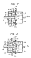
- Figs. 7 and 8 show another embodiment of the present invention, which differs from the embodiment in Figs. 5 and 6 in that the resiliency of the first resilient member 26 is set as being larger than that of the second resilient member 28 such that, when the valve seat 16 is in the first preset position as shown in Fig. 7, the second resilient member 28 urges the valve member 14 in the opposite direction to the urging direction of the first resilient member 26 so that the valve member 14 is moved by a difference between the resiliency of the first resilient member 26 and that of the second resilient member 28 to regulate the fuel pressure to the first fuel pressure value and, when the valve seat 16 is in the second preset position as shown in Fig. 8, the fuel pressure is regulated to the second fuel pressure value by the urging force exerted on the valve member 14 by the first resilient member 26.
- Figs. 9 and 10 show another embodiment of the present invention.
- the fuel pressure regulating device 7 has a partition wall 35 which divides the fluid pressure regulating chamber S1 into two section S1a and S1b and a second diaphragm 13a which supports a bottom of the valve seat 16.
- the section S1a is in communication with the fuel pump 3 and the section S1b serves to provide a fluid overflow passage.
- the valve seat 16 is slidable through the partition wall 35a and the third resilient member 30 serves to urge the second diaphragm 13a through a stopper 32 in a direction shown by an arrow.
- the stopper 32 serves to limit an amount of movement of the diaphragm 13a in the reverse direction.
- An electromagnetic valve 40 is provided which is actuated electrically to introduce a pressure of the suction tube 11 or atmospheric pressure to an air chamber 37 defined by the second diaphragm 13a and a cover member 23 ⁇ .
- the electromagnetic valve 40 is controlled in response to the engine operating condition by the controller 10.
- the spring holder 29 ⁇ is separated from the spring stopper 31 and contacts with the valve member 14.
- the second resilient member 28 also affects the valve member 14 jointly to increase the fuel pressure at which the valve member 14 is separated from the valve seat 16 by an amount corresponding to the resilient force of the second resilient member 28. That is the fuel pressure in the chamber S1a is maintained at the second preset value determined by the first and second resilient members 26 and 28.
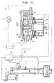
- Figs. 11 and 12 show another embodiment of the present invention which is similar to the embodiment shown in Figs. 9 and 10 except that the electromagnetic switch valve 40 is provided in the fuel pressure regulator 7 as a unit and the third resilient member 30 urges the second diaphragm 13a in the reverse direction to the case of the preceding embodiment against the pressurized fuel introduced to the chamber 37 through the electromagnetic switch valve 40 as shown in Fig. 11.
- the holding member 29 ⁇ is separated from the stopper 31 and brought into contact with the valve member 14 to thereby introduce the second resilient member 28 to the valve member 14 so that the fuel pressure at which the valve member 14 is separated from the valve seat 16 is increased by an amount corresponding to the resiliency of the second resilient membe 28 and the same effect as that obtained in the preceding embodiment is obtained.
- the fuel pressure regulator comprises a valve member fixedly mounted on a first diaphragm having one surface subjected to pressurized fuel, a plurality of resilient members in the form of spring for biassing the valve member in an opposite direction to the fuel pressure and a cylindrical valve seat and operates such that, when the fuel pressure is within a predetermined range, one of the resilient members affects either the valve seat or valve member which is biassed by the other resilient member. Therefore, it becomes possible to vary the fuel pressure considerably with minimum drive force. With a use of a third diaphragm, in addition thereto, it becomes possible to move the valve seat itself.
Landscapes
- Engineering & Computer Science (AREA)
- Chemical & Material Sciences (AREA)
- Combustion & Propulsion (AREA)
- Mechanical Engineering (AREA)
- General Engineering & Computer Science (AREA)
- Physics & Mathematics (AREA)
- Power Engineering (AREA)
- Fluid Mechanics (AREA)
- General Physics & Mathematics (AREA)
- Automation & Control Theory (AREA)
- Fuel-Injection Apparatus (AREA)
- Fluid-Driven Valves (AREA)
Claims (5)
- Kraftstoffdruckregler für einen Verbrennungsmotor, mit einem ersten Diaphragma (13), einer Kraftstoffdruckregelungskammer (S1), welche zum Teil durch das erste Diaphragma (13) definiert wird, einem Ventilsitz (16), der in der Kraftstoffdruckregelungskammer (S1) vorgesehen ist, wobei der Ventilsitz (16) eine Überlauföffnung (16a) aufweist, einem Ventilteil (14), welches fest auf dem ersten Diaphragma (13) montiert ist, und relativ bezüglich des Ventilsitzes (16) bewegbar ist, einem ersten federnden Teil (26) zum Vorspannen des Ventilteiles (14) auf den Ventilsitz (16), um die Überlauföffnung (16a) davon zu schließen, einem zweiten federnden Teil (28), welches angepaßt ist, eine zusätzliche Vorspannkraft auf das Ventilteil (14) vorzusehen, um dadurch einen Kraftstoffdruck in der Kraftstoffdruckregelungskammer (S1), wenn benötigt, zu erhöhen, und einer auf eine Betriebsbedingung des Verbrennungsmotors ansprechende Treibereinrichtung (27), um das zweite federnde Teil (28) selektiv in Betrieb zu setzen, wodurch die Treibereinrichtung (27), wenn die Betriebsbedingung eine vorbestimmte Bedingung überschreitet, bewirkt, daß das zweite federnde Teil (28) die zusätzliche vorspannende Kraft auf das Ventilteil (14) ausübt, um dadurch einen Kraftstoffdruck in der Kraftstoffdruckregelungskammer (S1) zu erhöhen,
dadurch gekennzeichnet, daß der Ventilsitz (16) in seiner axialen Richtung bewegbar ist, und dadurch, daß ein drittes federndes Teil (30) vorgesehen ist, welches den bewegbaren Ventilsitz bezüglich des Ventilteiles (14) vorspannt. - Kraftstoffdruckregler nach Anspruch 1,
dadurch gekennzeichnet, daß die Treibereinrichtung (27) einen Elektromagneten umfaßt, welcher fest in der Kraftstoffdruckregelungskammer (S1) vorgesehen ist, ein Halteteil (29), welches an einem Ende des zweiten federnden Teiles (28) angebracht ist und normalerweise von einem Anschlag (31) gehalten wird, der auf einer Seite des ersten Diaphragmas (13) entgegengesetzt der Druckregelungskammer (S1) vorgesehen ist, um das zweite federnde Teil (28) außer Betrieb zu halten, und das dritte federnde Teil (30) auf der Seite der Druckregelungskammer (S1) vorgesehen ist, den Ventilsitz (16) auf das Ventilteil (14) vorzuspannen, wobei der Elektromagnet (27) angepaßt ist, den Ventilsitz (16) gegen eine federnde Kraft des dritten federnden Teiles (30) anzuziehen und den Ventilsitz (16) freizugeben, um letzeren zu erlauben, das Ventilteil (14) zu schieben, bis letzteres mit dem Halteteil (29) in Eingriff tritt, um dadurch zu bewirken, daß das zweite federnde Teil (28) in Betrieb ist. - Kraftstoffdruckregler nach Anspruch 1,
dadurch gekennzeichnet, daß der bewegbare Ventilsitz (16) fest von einem zweiten Diaphragma (13a) getragen wird, um mit dem zweiten Diaphragma (13a) bewegbar zu sein, wobei die Druckregelungskammer (S1) zwischen den ersten und zweiten Diaphragmen (13, 13a) definiert ist und die Treibereinrichtung ein elektromagnetisches Schaltventil (40) umfaßt, um selektiv einen Druck auf das zweite Diaphragma (13a) zu liefern, um letzteres zu dem ersten Diaphragma (13) hin vorzuspannen. - Kraftstoffdruckregler nach Anspruch 3,
dadurch gekennzeichnet, daß das dritte federnde Teil (30) das zweite Diaphragma (13a) zu dem ersten Diaphragma (13) hin vorspannt. - Kraftstoffdruckregler nach Anspruch 3,
dadurch gekennzeichnet, daß das dritte federnde Teil (30) das zweite Diaphragma (13a) von dem ersten Diaphragma (13) weg vorspannt.
Applications Claiming Priority (6)
| Application Number | Priority Date | Filing Date | Title |
|---|---|---|---|
| JP61128610A JPS62284960A (ja) | 1986-06-03 | 1986-06-03 | 流体圧力調整装置 |
| JP128610/86 | 1986-06-03 | ||
| JP61158538A JPS6316166A (ja) | 1986-07-04 | 1986-07-04 | 機関の燃料圧力調整装置 |
| JP158538/86 | 1986-07-04 | ||
| JP233579/86 | 1986-09-30 | ||
| JP61233579A JPS6388269A (ja) | 1986-09-30 | 1986-09-30 | 機関の燃料圧力調整装置 |
Publications (3)
| Publication Number | Publication Date |
|---|---|
| EP0248411A2 EP0248411A2 (de) | 1987-12-09 |
| EP0248411A3 EP0248411A3 (en) | 1989-07-19 |
| EP0248411B1 true EP0248411B1 (de) | 1992-03-25 |
Family
ID=27315779
Family Applications (1)
| Application Number | Title | Priority Date | Filing Date |
|---|---|---|---|
| EP87108013A Expired - Lifetime EP0248411B1 (de) | 1986-06-03 | 1987-06-03 | Druckregler für Kraftstoff |
Country Status (4)
| Country | Link |
|---|---|
| US (1) | US4829964A (de) |
| EP (1) | EP0248411B1 (de) |
| KR (1) | KR900002315B1 (de) |
| DE (1) | DE3777690D1 (de) |
Cited By (1)
| Publication number | Priority date | Publication date | Assignee | Title |
|---|---|---|---|---|
| DE19522514B4 (de) * | 1994-06-21 | 2007-08-09 | Walbro Corp., Cass City | Einweg-Kraftstoffzuführanlage für eine Brennkraftmaschine |
Families Citing this family (25)
| Publication number | Priority date | Publication date | Assignee | Title |
|---|---|---|---|---|
| JP2757261B2 (ja) * | 1989-04-28 | 1998-05-25 | ヤマハ発動機株式会社 | 燃料噴射装置 |
| US5174262A (en) * | 1989-04-14 | 1992-12-29 | Brunswick Corporation | Control valve for fuel injection |
| US5063886A (en) * | 1989-09-18 | 1991-11-12 | Toyota Jidosha Kabushiki Kaisha | Two-stroke engine |
| DE4016055A1 (de) * | 1990-05-18 | 1991-11-21 | Bosch Gmbh Robert | Kraftstoffversorgungssystem fuer eine brennkraftmaschine |
| US5133323A (en) * | 1991-06-25 | 1992-07-28 | Siemens Automotive L.P. | Intake manifold pressure compensation for the closed-loop pressure regulation of a fuel pump |
| AT396850B (de) * | 1991-09-09 | 1993-12-27 | Vaillant Gmbh | Servodruckregler |
| US5237975A (en) * | 1992-10-27 | 1993-08-24 | Ford Motor Company | Returnless fuel delivery system |
| JP2853504B2 (ja) * | 1993-03-16 | 1999-02-03 | 日産自動車株式会社 | 内燃機関の燃料噴射装置 |
| US5727529A (en) * | 1994-01-14 | 1998-03-17 | Walbro Corporation | Pressure control valve for a fuel system |
| DE4414242A1 (de) * | 1994-04-23 | 1995-10-26 | Bosch Gmbh Robert | Kraftstoffeinspritzeinrichtung für Brennkraftmaschinen |
| US5471959A (en) * | 1994-08-31 | 1995-12-05 | Sturman; Oded E. | Pump control module |
| DE19539883B4 (de) * | 1995-05-26 | 2011-06-01 | Robert Bosch Gmbh | Kraftstoffversorgungsanlage und Verfahren zum Betreiben einer Brennkraftmaschine |
| US5605133A (en) * | 1995-11-20 | 1997-02-25 | Walbro Corporation | Fuel rail pressure control |
| DE19631167B4 (de) * | 1996-08-01 | 2005-08-11 | Siemens Ag | Referenzdruckventil |
| DE10005589A1 (de) * | 2000-02-09 | 2001-08-16 | Bayerische Motoren Werke Ag | Kraftstoffversorgungsanlage für eine Brennkraftmaschine |
| US6644288B2 (en) * | 2001-05-17 | 2003-11-11 | Yamada Mfg. Co., Ltd. | Engine |
| DE102005036188A1 (de) | 2005-08-02 | 2007-02-08 | Robert Bosch Gmbh | Kraftstoffversorgunssystem |
| WO2008149383A1 (en) * | 2007-06-08 | 2008-12-11 | Ucal Fuel Systems Limited | Fuel injection system of a vehicle |
| JP4704407B2 (ja) * | 2007-10-26 | 2011-06-15 | 愛三工業株式会社 | 燃料供給装置 |
| JP4732429B2 (ja) * | 2007-12-18 | 2011-07-27 | 愛三工業株式会社 | 調圧弁及び燃料供給装置 |
| WO2011001478A1 (ja) * | 2009-07-03 | 2011-01-06 | トヨタ自動車株式会社 | 燃料供給装置 |
| JP5340906B2 (ja) * | 2009-12-16 | 2013-11-13 | 愛三工業株式会社 | 圧力制御装置 |
| DE112010005250B8 (de) * | 2010-02-10 | 2015-09-10 | Toyota Jidosha Kabushiki Kaisha | Regelvorrichtung für den Strömungsmitteldruck und Kraftstoffversorgungseinrichtung |
| US8522751B2 (en) * | 2010-09-01 | 2013-09-03 | Honda Motor Co., Ltd. | Fuel pressure regulator for a motor vehicle |
| ITRM20110203A1 (it) | 2011-04-21 | 2012-10-22 | Icomet Spa | Riduttore regolatore di pressione per l'alimentazione con metano od altri combustibili simili di motori a combustione interna |
Family Cites Families (15)
| Publication number | Priority date | Publication date | Assignee | Title |
|---|---|---|---|---|
| DE2351203A1 (de) * | 1972-09-07 | 1975-04-17 | Bosch Gmbh Robert | Kraftstoffversorgungsanlage |
| DE2327295C3 (de) * | 1973-05-29 | 1978-08-31 | Robert Bosch Gmbh, 7000 Stuttgart | Kraftstoffversorgungsanlage für Brennkraftmaschinen |
| JPS5053722A (de) * | 1973-09-12 | 1975-05-13 | ||
| DE2520322C3 (de) * | 1975-05-07 | 1979-02-15 | Robert Bosch Gmbh, 7000 Stuttgart | Kraftstoffeinspritzanlage für Brennkraftmaschinen |
| GB1546074A (en) * | 1975-05-15 | 1979-05-16 | Tecalemit Ltd | Fuel injection systems for internal combustion engine |
| DE2607366A1 (de) * | 1976-02-24 | 1977-09-01 | Bosch Gmbh Robert | Kraftstoffeinspritzanlage |
| JPS52148729A (en) * | 1976-06-03 | 1977-12-10 | Ntn Toyo Bearing Co Ltd | Fuel injector |
| DE2628666A1 (de) * | 1976-06-25 | 1977-12-29 | Bosch Gmbh Robert | Warmlaufsteuervorrichtung fuer eine kraftstoffversorgungsanlage |
| DE2757977A1 (de) * | 1977-12-24 | 1979-06-28 | Audi Nsu Auto Union Ag | Kraftstoff-einspritzanlage |
| US4200073A (en) * | 1978-06-19 | 1980-04-29 | General Motors Corporation | Electronic throttle body fuel injection system |
| GB2070802B (en) * | 1980-01-31 | 1984-08-22 | Nissan Motor | Control of fuel supply to an ic engine |
| JPS5827874A (ja) * | 1981-08-11 | 1983-02-18 | Mitsubishi Electric Corp | 機関の燃料噴射装置 |
| US4421089A (en) * | 1982-07-19 | 1983-12-20 | The Bendix Corporation | Fuel metering apparatus |
| JPS5943932A (ja) * | 1982-09-02 | 1984-03-12 | Mitsubishi Electric Corp | 機関の燃料圧力調整装置 |
| JPS59190444A (ja) * | 1983-04-12 | 1984-10-29 | Isuzu Motors Ltd | タ−ボチヤ−ジヤを有する内燃エンジン用の燃料供給装置 |
-
1987
- 1987-06-03 EP EP87108013A patent/EP0248411B1/de not_active Expired - Lifetime
- 1987-06-03 KR KR1019870005603A patent/KR900002315B1/ko not_active Expired
- 1987-06-03 US US07/057,079 patent/US4829964A/en not_active Expired - Lifetime
- 1987-06-03 DE DE8787108013T patent/DE3777690D1/de not_active Expired - Lifetime
Cited By (1)
| Publication number | Priority date | Publication date | Assignee | Title |
|---|---|---|---|---|
| DE19522514B4 (de) * | 1994-06-21 | 2007-08-09 | Walbro Corp., Cass City | Einweg-Kraftstoffzuführanlage für eine Brennkraftmaschine |
Also Published As
| Publication number | Publication date |
|---|---|
| DE3777690D1 (de) | 1992-04-30 |
| US4829964A (en) | 1989-05-16 |
| KR880000689A (ko) | 1988-03-28 |
| EP0248411A2 (de) | 1987-12-09 |
| EP0248411A3 (en) | 1989-07-19 |
| KR900002315B1 (ko) | 1990-04-11 |
Similar Documents
| Publication | Publication Date | Title |
|---|---|---|
| EP0248411B1 (de) | Druckregler für Kraftstoff | |
| JP2747428B2 (ja) | デマンド燃料圧レギュレータ | |
| US4986246A (en) | Valve for the metered admixture of volatilized fuel to the fuel-air mixture of an internal combustion engine | |
| JP3914583B2 (ja) | デマンド燃料圧力調整器を具備したノーリターン燃料装置 | |
| US4284039A (en) | Pressure regulator for injection systems for internal combustion engines | |
| US4732131A (en) | Fuel line purging device | |
| EP0198381B1 (de) | Brennstoffdruckregelvorrichtung | |
| US4648368A (en) | Fuel injection system | |
| US4469079A (en) | Exhaust gas recirculation (EGR) system | |
| US4608208A (en) | Control valve device | |
| CA1175311A (en) | Idle control valve | |
| US5357934A (en) | Apparatus for controlling pressure within fuel tank | |
| US4196704A (en) | Idle speed control actuator | |
| JP3742996B2 (ja) | 燃料供給装置 | |
| US4872437A (en) | Fuel pressure regulator for internal combustion engine | |
| US4601277A (en) | System for combined EGR and idle speed control | |
| US4088102A (en) | Auxiliary acceleration fuel feed device in an internal combustion engine | |
| US4020818A (en) | Oil pressure delay check valve and pressure switch for shutting off diesel engine upon drop in oil pressure | |
| GB2096239A (en) | Regulation of i c engine idling speed by throttle bypass valve control | |
| US4366835A (en) | Electromagnetic flow control valve | |
| US4141330A (en) | Pressure regulating valve for fuel injection systems | |
| JPS6388269A (ja) | 機関の燃料圧力調整装置 | |
| JPS6341665A (ja) | 機関の燃料圧力調整装置 | |
| US3789815A (en) | Temperature responsive control device | |
| US4129104A (en) | Ignition timing control device of the negative pressure actuation type |
Legal Events
| Date | Code | Title | Description |
|---|---|---|---|
| PUAI | Public reference made under article 153(3) epc to a published international application that has entered the european phase |
Free format text: ORIGINAL CODE: 0009012 |
|
| AK | Designated contracting states |
Kind code of ref document: A2 Designated state(s): DE FR GB |
|
| PUAL | Search report despatched |
Free format text: ORIGINAL CODE: 0009013 |
|
| AK | Designated contracting states |
Kind code of ref document: A3 Designated state(s): DE FR GB |
|
| 17P | Request for examination filed |
Effective date: 19891220 |
|
| 17Q | First examination report despatched |
Effective date: 19900209 |
|
| GRAA | (expected) grant |
Free format text: ORIGINAL CODE: 0009210 |
|
| AK | Designated contracting states |
Kind code of ref document: B1 Designated state(s): DE FR GB |
|
| REF | Corresponds to: |
Ref document number: 3777690 Country of ref document: DE Date of ref document: 19920430 |
|
| ET | Fr: translation filed | ||
| PLBE | No opposition filed within time limit |
Free format text: ORIGINAL CODE: 0009261 |
|
| STAA | Information on the status of an ep patent application or granted ep patent |
Free format text: STATUS: NO OPPOSITION FILED WITHIN TIME LIMIT |
|
| 26N | No opposition filed | ||
| REG | Reference to a national code |
Ref country code: GB Ref legal event code: IF02 |
|
| PGFP | Annual fee paid to national office [announced via postgrant information from national office to epo] |
Ref country code: GB Payment date: 20060531 Year of fee payment: 20 |
|
| PGFP | Annual fee paid to national office [announced via postgrant information from national office to epo] |
Ref country code: DE Payment date: 20060601 Year of fee payment: 20 |
|
| PGFP | Annual fee paid to national office [announced via postgrant information from national office to epo] |
Ref country code: FR Payment date: 20060608 Year of fee payment: 20 |
|
| REG | Reference to a national code |
Ref country code: GB Ref legal event code: PE20 |
|
| PG25 | Lapsed in a contracting state [announced via postgrant information from national office to epo] |
Ref country code: GB Free format text: LAPSE BECAUSE OF EXPIRATION OF PROTECTION Effective date: 20070602 |