EP0247553B1 - Dispositif pour couper des tubes sans copeaux - Google Patents
Dispositif pour couper des tubes sans copeaux Download PDFInfo
- Publication number
- EP0247553B1 EP0247553B1 EP87107546A EP87107546A EP0247553B1 EP 0247553 B1 EP0247553 B1 EP 0247553B1 EP 87107546 A EP87107546 A EP 87107546A EP 87107546 A EP87107546 A EP 87107546A EP 0247553 B1 EP0247553 B1 EP 0247553B1
- Authority
- EP
- European Patent Office
- Prior art keywords
- blade
- knife
- pipe
- rotary
- support
- Prior art date
- Legal status (The legal status is an assumption and is not a legal conclusion. Google has not performed a legal analysis and makes no representation as to the accuracy of the status listed.)
- Expired - Lifetime
Links
- 238000005520 cutting process Methods 0.000 title claims description 23
- 238000010008 shearing Methods 0.000 title claims description 4
- 230000000717 retained effect Effects 0.000 claims description 3
- 238000000926 separation method Methods 0.000 description 4
- 238000006073 displacement reaction Methods 0.000 description 2
- 206010034016 Paronychia Diseases 0.000 description 1
- 229910001315 Tool steel Inorganic materials 0.000 description 1
- 238000013459 approach Methods 0.000 description 1
- KUNSUQLRTQLHQQ-UHFFFAOYSA-N copper tin Chemical group [Cu].[Sn] KUNSUQLRTQLHQQ-UHFFFAOYSA-N 0.000 description 1
- 230000008878 coupling Effects 0.000 description 1
- 238000010168 coupling process Methods 0.000 description 1
- 238000005859 coupling reaction Methods 0.000 description 1
- 238000011161 development Methods 0.000 description 1
- 230000000694 effects Effects 0.000 description 1
- 238000004519 manufacturing process Methods 0.000 description 1
- 238000003825 pressing Methods 0.000 description 1
- 238000005096 rolling process Methods 0.000 description 1
- 230000001360 synchronised effect Effects 0.000 description 1
- 238000012360 testing method Methods 0.000 description 1
Images


Classifications
-
- B—PERFORMING OPERATIONS; TRANSPORTING
- B23—MACHINE TOOLS; METAL-WORKING NOT OTHERWISE PROVIDED FOR
- B23D—PLANING; SLOTTING; SHEARING; BROACHING; SAWING; FILING; SCRAPING; LIKE OPERATIONS FOR WORKING METAL BY REMOVING MATERIAL, NOT OTHERWISE PROVIDED FOR
- B23D21/00—Machines or devices for shearing or cutting tubes
- B23D21/14—Machines or devices for shearing or cutting tubes cutting inside the tube
Definitions
- the invention relates to a device for cutting a pipe section from a pipe with a stationary inner knife held on a mandrel on the inside of the pipe wall and an adjacent eccentrically movable by about the wall thickness of the pipe, surrounding the pipe rotating knife, which is due to an external applied rotary movement sheared to the inner knife.
- the rotary knife has a cutting edge that is composed of two superimposed circular rings. One circular ring is much larger than the pipe diameter, while the other circular ring just surrounds the pipe.
- the rotary knife is held in a disc which, with the help of two eccentrics, effects an eccentric displacement of the cutting edge during one revolution.
- the rotary knife is left to its own devices, which essentially shifts following the rolling movement on the tube into a specific angular position which does not correspond to the starting position. After the cut, the rotary knife must be realigned so that a new pipe section can be cut off.
- the second cutting direction means that the tube should first be cut at the top and bottom and then only laterally in the area of the second cutting direction.Because of the narrow knives inside and outside the tube wall, the lateral areas are not compressed even when the first cut is made in the first cutting direction to avoid, so that an unclean cut must be found later at these points.
- the support knife is kept freely movable in the shear direction, so that it produces less an active cutting action than rather only a support action.
- the invention proposes that a stationary outer knife surrounds the inner knife, that the rotary knife has a circular inner diameter, and that the mandrel in the area of the rotary knife has a central bearing for the starting position of the rotary knife, on which a rotatably mounted support knife is held whose cutting edge has the same eccentricity to the bearing as that of the rotary knife.
- the support knife follows the bearing of the mandrel eccentrically by the same amount, whereby the support knife is forced to rotate by the cutting movement of the pipe section. With each full revolution of the rotary knife, the eccentrically mounted support knife also rotates one full revolution.
- the support knife is connected in a rotationally fixed manner to the rotary knife in the operating position of the mandrel via a positive connection.
- the positive connection encompasses the pipe section to be cut off, so that only a short pipe section can be cut off in the case of a direct connection between the support knife and the rotary knife.
- the length of the maximum detachable pipe sections can be selected on the support knife and on the rotary knife.
- the rotary knife actually also performs a circular movement, it can be expedient to hold the tube by means of a clamping jaw on the side of the fixed knife facing away from the diameter, at least for the periods of the rotary knife circulation.
- the tool insert forming the rotary knife can be rotated within the tool carrier and is mounted essentially without play, for example with the aid of needle bearings. In this case there is only an eccentric movement, but no circular movement of the rotary knife; only the tool carrier executes the circular movement.
- This effort can e.g. B. may be necessary if the separated pipe sections must never have a marking of the separation process, so z. B. no grinding marks of the rotary knife may be present in the outer jacket of the pipe section.
- the support knife can be achieved.
- the other knives can also have a cutting edge that deviates from the circular shape in order to achieve one or more gates.
- the optimal shape can be determined by tests if necessary.
- the cutting edge in the knife carrier is preferably formed by an eccentrically inserted tool insert which can be designed to be interchangeable in order to adapt the device to different tube diameters. Since the required eccentricity primarily depends on the wall thickness of the pipe to be cut, a large number of pipe diameters can be cut off with the same eccentricity if appropriate knife sets are available for the fixed knife and the rotary and support knife. For thick-walled pipes, a knife carrier should then be kept ready, which has a different eccentricity, but can otherwise be fitted with the same tool inserts.
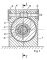
- FIG. 1 an embodiment of an apparatus according to the invention is shown in two sectional views, with Figures 2 and 3 differing in that once the starting position and once a sectional position is shown; the latter is also shown in FIG. 1.
- the device consists of a schematically indicated housing 1, which is mounted for example on a stand, a plate, a workbench or on a console as part of a manufacturing device.
- a stationary outer knife 2 is used, which consists of tool steel and is fixed in the housing 1.
- the fixing is done by clamping, by fixing screws or by pressing, in any case a relatively easy replacement is possible in order to be able to adapt the inner diameter of this fixed outer knife 2 to different pipe diameters.
- a mandrel 4 projects into the interior of the stationary outer knife 2, at the front end of which a stationary inner knife 5 is held by means of a washer 6 and a fastening screw 7.
- the mandrel 4 is adjusted so that the end side of the outer knife 2 and the inner knife 5 facing the center lie in one and the same plane, namely in the parting plane 20.
- This parting plane 20 is followed by a rotary knife 10, which consists of a knife carrier 11, consists of a tool insert 12 carrying the cutting edge and a worm wheel cut into the knife carrier 11.
- the unit thus formed is mounted within a bronze ring 13 and fixed in the axial direction with the aid of a cover 14.
- the drive is not shown and consists, for example, of a geared motor with a quick stop option.
- the device according to the invention is easily able to separate a pipe section 19 from a pipe 18.
- the tube 18 is pushed over the stationary inner knife 5 into the device via the mandrel 4, aligned in terms of length, for example with the aid of a stop, and the worm 15 is then driven until the rotary knife 10 has made a full revolution.
- the eccentric tool insert 12 arranged in the knife carrier 11 shears off the tube 18 in the parting plane 20, an increasing offset occurring between the tube piece 19 and the tube 18 after a cut, which ultimately leads to burr-free, smooth shearing.
- the now separated pipe section 19 and the pipe 18 are aligned again so that the device is ready for a new cut after the pipe section 19 has been removed.
- a support knife 22 within the rotary knife 10, which is provided with an eccentric bore and can rotate on a bearing 23 on the mandrel 4. It is adapted in diameter to that of the fixed inner knife 5; both knives are matched to the inside diameter of the tube 18 to be cut in each case. There is a clearance of 2 to 3 tenths of a millimeter for precision tubes, for tubes of poor quality or tubes with longitudinal seams, the clearance is considerably greater.
- the support knife 22 does not have its own drive but is carried along by the movement of the pipe section 19 during the cutting process, so it rotates a full revolution during a cutting process.
- a latching device is present, of which a pan 24 can be seen in the stationary inner knife 5 in FIGS. 1 to 3.
- a spring-loaded ball held in the support knife 22 snaps into this pan.
- This latching device quasi automatically performs a residual centering when the support knife 22 again approaches the starting position at the end of a separation process.
- the tool insert 12 runs during a cutting process around.
- a corresponding moment is exerted on the tube 18 at least at the beginning of the separation process.
- a clamping jaw 27 is guided in a slot 26, which can be placed on the pipe, for example with the aid of a pneumatic cylinder or the like, and thus brings about a clamping between itself and the remaining stationary outer knife 2.
- the outer knife 2, moreover, like the tool insert 12, is matched to the outer diameter of the tube 18, a small clearance of a few tenths of a millimeter being generally selected. Consequently, there is a very good osculation between the tube 18 and the stationary outer knife 2 below the clamping jaw 27, which prevents deformation of the tube at this point.
- the rotating rotary knife 10 can optionally produce grinding marks or grooves on the outside of the tube, which, depending on the intended use of the tube section 19, may be undesirable. In this case, it is advisable to mount the tool insert 12 within the knife carrier 11, so that there is virtually no relative movement between the tool insert 12 and the pipe section 19, if one disregards the shear movement.
- FIGS. Another exemplary embodiment of the invention is shown in FIGS. Components that correspond to those of the exemplary embodiment described above have been provided with the same reference numerals, with minor deviations the reference numerals have been indexed.
- the distinction essentially lies in the fact that the support knife 22 is forcibly moved together with the rotary knife 10, so that a completely synchronous movement of both movable knives occurs and of course when the dome 4 is movable.
- the support knife 22 carries on the side facing the mandrel 4 a flange 30 with two opposite, lateral guide surfaces or key surfaces, which are moved by a driver plate 28 with a correspondingly shaped window 29 for receiving the flange 30; the driver plate 28 is fastened to the knife carrier 11 by means of screws 31 and rotates with sufficient play within the cover 14 '.
- the mandrel 4 is withdrawn from the housing 1 to expose the severed pipe section, the form-locking connection prevailing between the flange 30 and the window 29 is released, again with a ball catch, a brake or similar device, the angular position of the support knife 22 relative to the mandrel 4 ensures.
- the mandrel 4 After pulling off the separated pipe section from the mandrel 4 via the front disk 6 ', the mandrel 4 is retracted into the housing 1, the flange 30 and the window 28 engaging again.
- a chamfer (not shown) provided on the front edge of the flange 30 can make it easier to find the desired position. Otherwise, a wide variety of positive connections can be formed for the positive driving connection between the driving plate 28 and the support knife 22, it is only important that the connection can be released by an axial displacement of the dome 4 and a reliable function is ensured.
- the flange 30 limits the length of the pipe sections to be separated. If longer pipe sections are to be produced, the length of the bearing is extended accordingly and a corresponding extension is used between the support knife 22 and the flange 30, for example in the form of a pipe which remains within the silhouette of the pipe section to be separated. A corresponding extension is also used between the driver plate 28 and the rotary knife 10, so that the flange 30 and the driver plate 28 are then each attached to the free ends of the extensions. The function is then retained.
- the extensions lie one inside the other and inside is the pipe section to be separated, which of course can also be shorter than the maximum possible length of a pipe section to be separated.
- a gear motor can be used to drive the worm 15, which is equipped with a quick stop facility.
- a drive motor with a quick stop coupling can be used, the functional sequence of which is such that the worm 15 is taken along by a full revolution while the motor is running. In the rest periods, the screw 15 is also clearly fixed in the predetermined latching position, so that the start and end positions are always the same.
Landscapes
- Engineering & Computer Science (AREA)
- Mechanical Engineering (AREA)
- Turning (AREA)
Claims (12)
Priority Applications (1)
| Application Number | Priority Date | Filing Date | Title |
|---|---|---|---|
| AT87107546T ATE55298T1 (de) | 1986-05-24 | 1987-05-23 | Vorrichtung zum spanlosen zertrennen von rohren. |
Applications Claiming Priority (4)
| Application Number | Priority Date | Filing Date | Title |
|---|---|---|---|
| DE3617587 | 1986-05-24 | ||
| DE3617587 | 1986-05-24 | ||
| DE19873707405 DE3707405A1 (de) | 1986-05-24 | 1987-03-07 | Vorrichtung zum spanlosen zertrennen von rohren |
| DE3707405 | 1987-03-07 |
Publications (2)
| Publication Number | Publication Date |
|---|---|
| EP0247553A1 EP0247553A1 (fr) | 1987-12-02 |
| EP0247553B1 true EP0247553B1 (fr) | 1990-08-08 |
Family
ID=25844080
Family Applications (1)
| Application Number | Title | Priority Date | Filing Date |
|---|---|---|---|
| EP87107546A Expired - Lifetime EP0247553B1 (fr) | 1986-05-24 | 1987-05-23 | Dispositif pour couper des tubes sans copeaux |
Country Status (3)
| Country | Link |
|---|---|
| EP (1) | EP0247553B1 (fr) |
| DE (2) | DE3707405A1 (fr) |
| ES (1) | ES2016950B3 (fr) |
Cited By (2)
| Publication number | Priority date | Publication date | Assignee | Title |
|---|---|---|---|---|
| US6874398B2 (en) | 2002-10-18 | 2005-04-05 | Spiro Sa | Assembly for cutting a tube |
| CN103990850A (zh) * | 2014-05-26 | 2014-08-20 | 东莞市晋诚机械有限公司 | 一种自动高速金属管材裁断机 |
Families Citing this family (6)
| Publication number | Priority date | Publication date | Assignee | Title |
|---|---|---|---|---|
| DE4130243B4 (de) * | 1990-08-17 | 2005-12-22 | Wilhelm Wittl | Vorrichtung zum Ausklinken von Rohren |
| WO1996039287A1 (fr) * | 1993-12-21 | 1996-12-12 | Dalumverken Ab | Dispositif de tronçonnage pour materiau tubulaire |
| SE526005C2 (sv) * | 2002-10-18 | 2005-06-14 | Spiro Sa | Anordning för kapning av rör, samt maskin innefattande sådan anordning |
| DE102010061191B4 (de) | 2010-12-13 | 2014-07-10 | Gustav Klauke Gmbh | Verfahren zum Durchtrennen eines Rohres und Vorrichtung zum Durchtrennen |
| DE102017110923B3 (de) | 2017-05-19 | 2018-08-02 | Rohrtrennzentrum GmbH | Vorrichtung zum Durchtrennen eines Rohres; Verfahren zum Durchtrennen eines Rohres |
| DE102017110922B4 (de) | 2017-05-19 | 2019-06-06 | Rohrtrennzentrum GmbH | Vorrichtung zum Durchtrennen eines Rohres; Verfahren zum Durchtrennen eines Rohres |
Family Cites Families (7)
| Publication number | Priority date | Publication date | Assignee | Title |
|---|---|---|---|---|
| US1930295A (en) * | 1929-02-23 | 1933-10-10 | American Electric Fusion Corp | Tubing cutter |
| GB749389A (en) * | 1953-08-22 | 1956-05-23 | William Henry Laban | Means for shearing heavy gauge tubing |
| SE355739B (fr) * | 1967-05-04 | 1973-05-07 | Dainippon Ink & Chemicals | |
| US3657951A (en) * | 1969-08-15 | 1972-04-25 | Harry S Clark | Tubular products cut-off and method |
| DE2916031A1 (de) * | 1979-04-20 | 1980-10-30 | Knaebel Horst | Verfahren und vorrichtung zum spanlosen abtrennen von abschnitten von profilstaeben o.dgl. |
| DE3118791A1 (de) * | 1980-08-05 | 1982-03-18 | Champion Spark Plug Co., Toledo, Ohio | Verfahren und vorrichtung zum abscheren von metallen |
| SE426030B (sv) * | 1981-04-22 | 1982-12-06 | Lagher Gunnar H | Anordning for kapning av ror |
-
1987
- 1987-03-07 DE DE19873707405 patent/DE3707405A1/de not_active Withdrawn
- 1987-05-23 DE DE8787107546T patent/DE3764181D1/de not_active Expired - Fee Related
- 1987-05-23 EP EP87107546A patent/EP0247553B1/fr not_active Expired - Lifetime
- 1987-05-23 ES ES87107546T patent/ES2016950B3/es not_active Expired - Lifetime
Cited By (3)
| Publication number | Priority date | Publication date | Assignee | Title |
|---|---|---|---|---|
| US6874398B2 (en) | 2002-10-18 | 2005-04-05 | Spiro Sa | Assembly for cutting a tube |
| CN103990850A (zh) * | 2014-05-26 | 2014-08-20 | 东莞市晋诚机械有限公司 | 一种自动高速金属管材裁断机 |
| CN103990850B (zh) * | 2014-05-26 | 2016-08-17 | 东莞市晋诚机械有限公司 | 一种自动高速金属管材裁断机 |
Also Published As
| Publication number | Publication date |
|---|---|
| ES2016950B3 (es) | 1990-12-16 |
| EP0247553A1 (fr) | 1987-12-02 |
| DE3707405A1 (de) | 1987-11-26 |
| DE3764181D1 (de) | 1990-09-13 |
Similar Documents
| Publication | Publication Date | Title |
|---|---|---|
| DE69014934T2 (de) | Vorrichtung zum Formen von Schraubennahtrohren. | |
| DE2602262B2 (de) | Vorrichtung für das Abkanten von topfförmigen, metallenen Werkstücken, insbesondere Dosenriimpfen u.dgl | |
| DE2610467A1 (de) | Vorrichtung zum ablaengen von rohren | |
| DE3000321C2 (de) | Rotierende Stanzvorrichtung | |
| DD201972A5 (de) | Vorrichtung zum gleichzeitigen durchtrennen von zwei fortlaufenden zigarettenstraengen | |
| DE3720630A1 (de) | Werkzeug zur umfangsschneidenden bearbeitung von werkstuecken, insbesondere zum bohren | |
| EP0247553A1 (fr) | Dispositif pour couper des tubes sans copeaux | |
| DE2618044B2 (de) | Gerät zum Durchführen von mechanischen Arbeitsgängen an dünnwandigen Rohren | |
| EP0065179A2 (fr) | Appareil pour découper un trou dans une bande de papier | |
| DE2542402A1 (de) | Papierbahnschneider | |
| DE2603343B2 (de) | Vorrichtung zum Zuschneiden von Dosen | |
| DE2903847C2 (fr) | ||
| DE2527634A1 (de) | Schneidvorrichtung | |
| DE2620768C2 (fr) | ||
| DE10053863C1 (de) | Verfahren und Vorrichtung zur Trennung eines Rohres | |
| DE69516813T2 (de) | Gerät zum Schneiden von Spiralrohr | |
| EP0684113A1 (fr) | Dispositif de coupe ayant un élément de coupe en forme de disque | |
| DE1652771C3 (de) | Längsfahrbare Vorrichtung zum Trennen von Rohren in Abschnitte bestimmter Länge | |
| CH340700A (de) | Verfahren zum Perforieren von Papier und Einrichtung zur Durchführung dieses Verfahrens | |
| DE3621978A1 (de) | Schneidmaschine fuer saeulenfoermiges material | |
| DE1502808C3 (de) | Rohrschere | |
| DE3314830C2 (fr) | ||
| EP0510400B1 (fr) | Cisaille rotative à tambours | |
| DE4013128A1 (de) | Verfahren und vorrichtung zum ausfraesen der innenwand eines unterirdisch verlegten kanalrohres | |
| DE3341005A1 (de) | Werkzeug zum trennen von rohren |
Legal Events
| Date | Code | Title | Description |
|---|---|---|---|
| PUAI | Public reference made under article 153(3) epc to a published international application that has entered the european phase |
Free format text: ORIGINAL CODE: 0009012 |
|
| AK | Designated contracting states |
Kind code of ref document: A1 Designated state(s): AT BE CH DE ES FR GB IT LI LU NL |
|
| 17P | Request for examination filed |
Effective date: 19880420 |
|
| 17Q | First examination report despatched |
Effective date: 19890712 |
|
| GRAA | (expected) grant |
Free format text: ORIGINAL CODE: 0009210 |
|
| ITF | It: translation for a ep patent filed | ||
| AK | Designated contracting states |
Kind code of ref document: B1 Designated state(s): AT BE CH DE ES FR GB IT LI LU NL |
|
| REF | Corresponds to: |
Ref document number: 55298 Country of ref document: AT Date of ref document: 19900815 Kind code of ref document: T |
|
| REF | Corresponds to: |
Ref document number: 3764181 Country of ref document: DE Date of ref document: 19900913 |
|
| GBT | Gb: translation of ep patent filed (gb section 77(6)(a)/1977) | ||
| ET | Fr: translation filed | ||
| ITTA | It: last paid annual fee | ||
| PLBE | No opposition filed within time limit |
Free format text: ORIGINAL CODE: 0009261 |
|
| STAA | Information on the status of an ep patent application or granted ep patent |
Free format text: STATUS: NO OPPOSITION FILED WITHIN TIME LIMIT |
|
| 26N | No opposition filed | ||
| EPTA | Lu: last paid annual fee | ||
| PGFP | Annual fee paid to national office [announced via postgrant information from national office to epo] |
Ref country code: LU Payment date: 19950501 Year of fee payment: 9 |
|
| PGFP | Annual fee paid to national office [announced via postgrant information from national office to epo] |
Ref country code: CH Payment date: 19950519 Year of fee payment: 9 |
|
| PGFP | Annual fee paid to national office [announced via postgrant information from national office to epo] |
Ref country code: AT Payment date: 19950523 Year of fee payment: 9 |
|
| PGFP | Annual fee paid to national office [announced via postgrant information from national office to epo] |
Ref country code: NL Payment date: 19950531 Year of fee payment: 9 |
|
| PGFP | Annual fee paid to national office [announced via postgrant information from national office to epo] |
Ref country code: BE Payment date: 19950609 Year of fee payment: 9 |
|
| PG25 | Lapsed in a contracting state [announced via postgrant information from national office to epo] |
Ref country code: LU Free format text: LAPSE BECAUSE OF NON-PAYMENT OF DUE FEES Effective date: 19960523 Ref country code: AT Effective date: 19960523 |
|
| PG25 | Lapsed in a contracting state [announced via postgrant information from national office to epo] |
Ref country code: LI Effective date: 19960531 Ref country code: CH Effective date: 19960531 Ref country code: BE Effective date: 19960531 |
|
| BERE | Be: lapsed |
Owner name: DEMGEN KARL-WILLI Effective date: 19960531 |
|
| PG25 | Lapsed in a contracting state [announced via postgrant information from national office to epo] |
Ref country code: NL Effective date: 19961201 |
|
| REG | Reference to a national code |
Ref country code: CH Ref legal event code: PL |
|
| NLV4 | Nl: lapsed or anulled due to non-payment of the annual fee |
Effective date: 19961201 |
|
| PGFP | Annual fee paid to national office [announced via postgrant information from national office to epo] |
Ref country code: GB Payment date: 19970407 Year of fee payment: 11 |
|
| PGFP | Annual fee paid to national office [announced via postgrant information from national office to epo] |
Ref country code: FR Payment date: 19970417 Year of fee payment: 11 |
|
| PGFP | Annual fee paid to national office [announced via postgrant information from national office to epo] |
Ref country code: ES Payment date: 19970531 Year of fee payment: 11 |
|
| PG25 | Lapsed in a contracting state [announced via postgrant information from national office to epo] |
Ref country code: GB Free format text: LAPSE BECAUSE OF NON-PAYMENT OF DUE FEES Effective date: 19980523 |
|
| PG25 | Lapsed in a contracting state [announced via postgrant information from national office to epo] |
Ref country code: ES Free format text: LAPSE BECAUSE OF NON-PAYMENT OF DUE FEES Effective date: 19980525 |
|
| PG25 | Lapsed in a contracting state [announced via postgrant information from national office to epo] |
Ref country code: FR Free format text: LAPSE BECAUSE OF NON-PAYMENT OF DUE FEES Effective date: 19980531 |
|
| GBPC | Gb: european patent ceased through non-payment of renewal fee |
Effective date: 19980523 |
|
| REG | Reference to a national code |
Ref country code: FR Ref legal event code: ST |
|
| PGFP | Annual fee paid to national office [announced via postgrant information from national office to epo] |
Ref country code: DE Payment date: 19990529 Year of fee payment: 13 |
|
| REG | Reference to a national code |
Ref country code: ES Ref legal event code: FD2A Effective date: 20000503 |
|
| PG25 | Lapsed in a contracting state [announced via postgrant information from national office to epo] |
Ref country code: DE Free format text: LAPSE BECAUSE OF NON-PAYMENT OF DUE FEES Effective date: 20010301 |
|
| PG25 | Lapsed in a contracting state [announced via postgrant information from national office to epo] |
Ref country code: IT Free format text: LAPSE BECAUSE OF NON-PAYMENT OF DUE FEES;WARNING: LAPSES OF ITALIAN PATENTS WITH EFFECTIVE DATE BEFORE 2007 MAY HAVE OCCURRED AT ANY TIME BEFORE 2007. THE CORRECT EFFECTIVE DATE MAY BE DIFFERENT FROM THE ONE RECORDED. Effective date: 20050523 |