EP0247553A1 - Dispositif pour couper des tubes sans copeaux - Google Patents
Dispositif pour couper des tubes sans copeaux Download PDFInfo
- Publication number
- EP0247553A1 EP0247553A1 EP87107546A EP87107546A EP0247553A1 EP 0247553 A1 EP0247553 A1 EP 0247553A1 EP 87107546 A EP87107546 A EP 87107546A EP 87107546 A EP87107546 A EP 87107546A EP 0247553 A1 EP0247553 A1 EP 0247553A1
- Authority
- EP
- European Patent Office
- Prior art keywords
- knife
- rotary
- pipe
- mandrel
- rotary knife
- Prior art date
- Legal status (The legal status is an assumption and is not a legal conclusion. Google has not performed a legal analysis and makes no representation as to the accuracy of the status listed.)
- Granted
Links
Images

Classifications
-
- B—PERFORMING OPERATIONS; TRANSPORTING
- B23—MACHINE TOOLS; METAL-WORKING NOT OTHERWISE PROVIDED FOR
- B23D—PLANING; SLOTTING; SHEARING; BROACHING; SAWING; FILING; SCRAPING; LIKE OPERATIONS FOR WORKING METAL BY REMOVING MATERIAL, NOT OTHERWISE PROVIDED FOR
- B23D21/00—Machines or devices for shearing or cutting tubes
- B23D21/14—Machines or devices for shearing or cutting tubes cutting inside the tube
Definitions
- the invention relates to a device for cutting a pipe section from a pipe without cutting, each with a fixed knife on the outside and inside of the pipe wall and an adjoining movable rotary knife surrounding the pipe, which shears off to the fixed knife as a result of an externally applied rotary movement moves and returns to its aligned starting position.
- Such a device is described for example in CH-PS 426 701.
- the rotary knife is shifted in a straight line, first in a given direction and back to the starting position and then in three further given directions, which are approximately vertical go right to the first direction.
- the cut is therefore not made in the conventional way as a result of a continuous movement in one direction, but rather through a sequence of deflections and resets into the starting position. If the first deflection already leads to a cut, the rest are superfluous, but if all deflections are required, the actual cut is not made, but the pipe is torn off in the parting line, which can result in an irregular cutting edge. In addition, almost the entire load rests on a first pair of rollers, so that very uneven wear of the device must be feared.
- the invention proposes that the cutting edge of the rotary knife is eccentrically movable, that the eccentricity corresponds at least approximately to the wall thickness of the tube, and that a drive is provided for a forward and backward partial rotation or for a single full rotation.
- the cutting direction changes constantly in the invention, so the cutting direction also rotates as the rotation progresses until the separation process is completed.
- this is the case after a pivoting of approximately 120 ° or later, with an infinitely large number of changes in cutting direction always taking place.
- the feared compression of certain pipe areas is thus eliminated once and for all. Rather, the cut surfaces of the cut tube are burr-free, smooth and can generally be used without reworking, in particular no straightening or deburring work is required.
- a partial revolution of the rotary knife can be achieved by a pneumatic or hydraulic swivel cylinder or with the help of a conventional pneumatic or hydraulic cylinder in connection with a toothed rack, which then engages in an external toothing on the rotary knife.
- a worm gear is preferably used, which is stopped after a single rotation in order to remove the separated pipe section and by pushing the pipe z. B. to prepare a new cut against a stop.
- the usually small play between the worm and the worm wheel is so small that the positioning accuracy that can be achieved is completely sufficient when the worm is controlled. Because of the slight displacement between the rotary knife and the fixed knife due to the eccentricity, a positioning error of up to one degree and more is not important. Regardless of a partial turn or a full turn, tubes or bowls can be trimmed, for example, after deep drawing.
- the cutting edge in the knife carrier is preferably formed by an eccentrically inserted tool insert which can be designed to be interchangeable in order to adapt the device to different tube diameters. Since the required eccentricity primarily depends on the wall thickness of the pipe to be cut, a large number of pipe diameters can be cut off with the same eccentricity if appropriate sets of knives are available for the fixed knives and the rotary knife. For thick-walled pipes, a knife carrier should then be kept ready, which has a different eccentricity, but can otherwise be fitted with the same tool inserts.
- a support knife inside the rotary knife, which prevents the pipe section or the pipe end from collapsing during the cutting.
- This support knife can have the previously known customary free mobility on the mandrel, for example it can be held in the central starting position with the aid of springs and pins and can be freely deflected.
- an annular rubber spring can also be selected between the mandrel and the inside of the annular support knife according to a development of the invention.
- the support knife can also be eccentric by the same amount be held on a bearing of the mandrel, the support knife then being forced to rotate by the cutting movement of the pipe section. With each full revolution of the rotary knife, the eccentrically mounted support knife also rotates one full revolution. To make it easier to maintain the aligned starting position, there can be a detachable latching connection between the support knife and one of the surrounding components.
- the support knife is connected in a rotationally fixed manner to the rotary knife in the operating position of the mandrel via a positive connection.
- the positive connection encompasses the pipe section to be cut off, so that only a short pipe section can be cut off in the case of a direct connection between the support knife and the rotary knife.
- the length of the maximum detachable pipe sections can be selected on the support knife and on the rotary knife.
- the rotary knife actually also performs a circular movement, it may be expedient to hold the pipe by a clamping jaw on the side of the stationary knife facing away from the rotary knife, at least for the periods of the rotary knife circulation.
- the tool insert forming the rotary knife is rotatable within the tool carrier and is mounted essentially free of play, for example with the aid of needle bearings. In this case there is only an eccentric movement, but no circular movement of the rotary knife; only the tool carrier executes the circular movement.
- This effort may be necessary, for example, if the separated pipe sections must in no case have a marking of the cutting process, for example, there may be no grinding marks on the rotary knife in the outer jacket of the pipe section.
- a defined gate which can be achieved, for example, by flattening the support knife.
- the other knives can also have a cutting edge that deviates from the circular shape in order to achieve one or more gates.
- the optimal shape can be determined by tests if necessary.
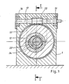
- FIG. 1 an embodiment of an apparatus according to the invention is shown in two sectional views, with Figures 2 and 3 differing in that once the starting position and once a sectional position is shown; the latter is also shown in FIG. 1.
- the device consists of a schematically indicated housing 1, which is mounted for example on a stand, a plate, a workbench or on a console as part of a manufacturing device.
- a stationary outer knife 2 is used, which consists of tool steel and is fixed in the housing 1.
- the fixing is done by clamping, by fixing screws or by pressing, in any case a relatively easy replacement is possible in order to be able to adapt the inner diameter of this fixed outer knife 2 to different pipe diameters.
- a mandrel 4 projects into the interior of the stationary outer knife 2, at the front end of which a stationary inner knife 5 is held by means of a washer 6 and a fastening screw 7.
- the mandrel 4 is adjusted such that the end side of the outer knife 2 and the inner knife 5 facing the center lie in one and the same plane, namely in the parting plane 20.
- This parting plane 20 is followed by a rotary knife 10 which consists of a knife holder 11, a tool insert 12 carrying the cutting edge and a worm wheel cut into the knife holder 11.
- the unit thus formed is mounted within a bronze ring 13 and fixed in the axial direction with the aid of a cover 14.
- the drive is not shown and consists, for example, of a geared motor with a quick stop option.
- the device according to the invention is easily able to separate a pipe section 19 from a pipe 18.
- the tube 18 is pushed over the stationary inner knife 5 into the device via the mandrel 4, aligned in terms of length, for example with the aid of a stop, and the worm 15 is then driven until the rotary knife 10 has made a full revolution.
- the eccentric tool insert 12 arranged in the knife carrier 11 shears off the tube 18 in the parting plane 20, an increasing offset occurring between the tube piece 19 and the tube 18 after a cut, which ultimately leads to burr-free, smooth shearing.
- the now separated pipe section 19 and the pipe 18 are aligned again so that the device is ready for a new cut after the pipe section 19 has been removed.
- a support knife 22 within the rotary knife 10, which is provided with an eccentric bore and can rotate on a bearing 23 on the mandrel 4. It is adapted in diameter to that of the fixed inner knife 5; both meas water are matched to the inside diameter of the tube 18 to be cut. There is a clearance of 2 to 3 tenths of a millimeter for precision tubes, for tubes of poor quality or tubes with longitudinal seams, the clearance is considerably greater.
- the support knife 22 does not have its own drive but is carried along by the movement of the pipe section 19 during the cutting process, so it rotates a full revolution during a cutting process.
- a latching device is present, of which a pan 24 can be seen in the stationary inner knife 5 in FIGS. 1 to 3.
- a spring-loaded ball held in the support knife 22 snaps into this pan.
- This latching device quasi automatically performs a residual centering when the support knife 22 again approaches the starting position at the end of a separation process.
- the tool insert 12 rotates during a cutting process.
- a corresponding moment is exerted on the tube 18 at least at the beginning of the separation process.
- a clamping jaw 27 is guided in a slot 26, which can be placed on the pipe, for example with the aid of a pneumatic cylinder or the like, and thus brings about a clamping between itself and the remaining stationary outer knife 2.
- the outer knife 2, moreover, like the tool insert 12, is matched to the outer diameter of the tube 18, a small clearance of a few tenths of a millimeter being generally selected. Consequently, there is a very good osculation between the tube 18 and the stationary outer knife 2 below the clamping jaw 27, which prevents deformation of the tube at this point.
- the rotating rotary knife 10 can on the outside of the pipe, if necessary, produce grinding marks or grooves which, depending on the intended use of the pipe section 19, may be undesirable. In this case, it is advisable to mount the tool insert 12 within the knife carrier 11, so that there is virtually no relative movement between the tool insert 12 and the pipe section 19, if one disregards the shear movement.
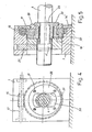
- FIGS. Another exemplary embodiment of the invention is shown in FIGS. Components that correspond to those of the exemplary embodiment described above have been provided with the same reference numerals, with minor deviations the reference numerals have been indexed.
- the distinction is essentially that the support knife 22 is forcibly moved together with the rotary knife 10, so that a completely synchronous movement of both movable knives and of course occurs when the mandrel 4 is movable.
- the support knife 22 carries on the side facing the mandrel 4 a flange 28 with two opposite, lateral guide surfaces or key surfaces, which are moved by a driver plate 28 with a correspondingly shaped window 29 for receiving the flange 30; the driver plate 28 is fastened to the knife carrier 11 with the aid of screws 31 and rotates with sufficient play within the cover 14 ⁇ .
- the mandrel 4 is withdrawn from the housing 1 to expose the severed pipe section, the form-locking connection prevailing between the flange 30 and the window 29 is released, again with a ball catch, a brake or similar device, the angular position of the support knife 22 relative to the mandrel 4 ensures.
- the mandrel 4 After pulling off the separated pipe section from the mandrel 4 via the front disk 6 ', the mandrel 4 is retracted into the housing 1, the flange 30 and the window 28 engaging again.
- a chamfer (not shown) provided on the front edge of the flange 30 can be used to locate the Make debit easier. Otherwise, a wide variety of positive connections can be formed for the positive driving connection between the driving plate 28 and the support knife 22, it is only important that the connection can be released by an axial displacement of the mandrel 4 and a reliable function is ensured.
- the flange 30 limits the length of the pipe sections to be separated. If longer pipe sections are to be produced, the length of the bearing is extended accordingly and a corresponding extension is used between the support knife 22 and the flange 30, for example in the form of a pipe which remains within the silhouette of the pipe section to be separated. A corresponding extension is also used between the driver plate 28 and the rotary knife 10, so that the flange 30 and the driver plate 28 are then each attached to the free ends of the extensions. The function is then retained.
- the extensions lie one inside the other and inside is the pipe section to be separated, which of course can also be shorter than the maximum possible length of a pipe section to be separated.
- a gear motor can be used to drive the worm 15, which is equipped with a quick stop facility.
- a drive motor with a quick stop coupling can be used, the functional sequence of which is such that the worm 15 is taken along by a full revolution while the motor is running. In the rest periods, the screw 15 is also clearly fixed in the predetermined latching position, so that the start and end positions are always the same.
Landscapes
- Engineering & Computer Science (AREA)
- Mechanical Engineering (AREA)
- Turning (AREA)
Priority Applications (1)
| Application Number | Priority Date | Filing Date | Title |
|---|---|---|---|
| AT87107546T ATE55298T1 (de) | 1986-05-24 | 1987-05-23 | Vorrichtung zum spanlosen zertrennen von rohren. |
Applications Claiming Priority (4)
| Application Number | Priority Date | Filing Date | Title |
|---|---|---|---|
| DE3617587 | 1986-05-24 | ||
| DE3617587 | 1986-05-24 | ||
| DE19873707405 DE3707405A1 (de) | 1986-05-24 | 1987-03-07 | Vorrichtung zum spanlosen zertrennen von rohren |
| DE3707405 | 1987-03-07 |
Publications (2)
| Publication Number | Publication Date |
|---|---|
| EP0247553A1 true EP0247553A1 (fr) | 1987-12-02 |
| EP0247553B1 EP0247553B1 (fr) | 1990-08-08 |
Family
ID=25844080
Family Applications (1)
| Application Number | Title | Priority Date | Filing Date |
|---|---|---|---|
| EP87107546A Expired - Lifetime EP0247553B1 (fr) | 1986-05-24 | 1987-05-23 | Dispositif pour couper des tubes sans copeaux |
Country Status (3)
| Country | Link |
|---|---|
| EP (1) | EP0247553B1 (fr) |
| DE (2) | DE3707405A1 (fr) |
| ES (1) | ES2016950B3 (fr) |
Cited By (4)
| Publication number | Priority date | Publication date | Assignee | Title |
|---|---|---|---|---|
| WO1996039287A1 (fr) * | 1993-12-21 | 1996-12-12 | Dalumverken Ab | Dispositif de tronçonnage pour materiau tubulaire |
| WO2004035239A2 (fr) * | 2002-10-18 | 2004-04-29 | Spiro S.A. | Ensemble permettant de decouper un tube |
| US6874398B2 (en) | 2002-10-18 | 2005-04-05 | Spiro Sa | Assembly for cutting a tube |
| DE102017110922A1 (de) * | 2017-05-19 | 2018-11-22 | Rohrtrennzentrum GmbH | Vorrichtung zum Durchtrennen eines Rohres; Verfahren zum Durchtrennen eines Rohres |
Families Citing this family (4)
| Publication number | Priority date | Publication date | Assignee | Title |
|---|---|---|---|---|
| DE4130243B4 (de) * | 1990-08-17 | 2005-12-22 | Wilhelm Wittl | Vorrichtung zum Ausklinken von Rohren |
| DE102010061191B4 (de) | 2010-12-13 | 2014-07-10 | Gustav Klauke Gmbh | Verfahren zum Durchtrennen eines Rohres und Vorrichtung zum Durchtrennen |
| CN103990850B (zh) * | 2014-05-26 | 2016-08-17 | 东莞市晋诚机械有限公司 | 一种自动高速金属管材裁断机 |
| DE102017110923B3 (de) | 2017-05-19 | 2018-08-02 | Rohrtrennzentrum GmbH | Vorrichtung zum Durchtrennen eines Rohres; Verfahren zum Durchtrennen eines Rohres |
Citations (7)
| Publication number | Priority date | Publication date | Assignee | Title |
|---|---|---|---|---|
| US1930295A (en) * | 1929-02-23 | 1933-10-10 | American Electric Fusion Corp | Tubing cutter |
| GB749389A (en) * | 1953-08-22 | 1956-05-23 | William Henry Laban | Means for shearing heavy gauge tubing |
| US3657951A (en) * | 1969-08-15 | 1972-04-25 | Harry S Clark | Tubular products cut-off and method |
| DE1752288B2 (de) * | 1967-05-04 | 1974-02-21 | Dainippon Ink And Chemicals Inc., Tokio | Schneidvorrichtung für Rohre, Stabeisen und Formstahl verschiedener Profile |
| DE2916031A1 (de) * | 1979-04-20 | 1980-10-30 | Knaebel Horst | Verfahren und vorrichtung zum spanlosen abtrennen von abschnitten von profilstaeben o.dgl. |
| DE3118791A1 (de) * | 1980-08-05 | 1982-03-18 | Champion Spark Plug Co., Toledo, Ohio | Verfahren und vorrichtung zum abscheren von metallen |
| DE3214275A1 (de) * | 1981-04-22 | 1982-11-18 | A.O. Arkitektkontor AB, 11625 Stockholm | Rohrabtrennapparat |
-
1987
- 1987-03-07 DE DE19873707405 patent/DE3707405A1/de not_active Withdrawn
- 1987-05-23 EP EP87107546A patent/EP0247553B1/fr not_active Expired - Lifetime
- 1987-05-23 ES ES87107546T patent/ES2016950B3/es not_active Expired - Lifetime
- 1987-05-23 DE DE8787107546T patent/DE3764181D1/de not_active Expired - Fee Related
Patent Citations (7)
| Publication number | Priority date | Publication date | Assignee | Title |
|---|---|---|---|---|
| US1930295A (en) * | 1929-02-23 | 1933-10-10 | American Electric Fusion Corp | Tubing cutter |
| GB749389A (en) * | 1953-08-22 | 1956-05-23 | William Henry Laban | Means for shearing heavy gauge tubing |
| DE1752288B2 (de) * | 1967-05-04 | 1974-02-21 | Dainippon Ink And Chemicals Inc., Tokio | Schneidvorrichtung für Rohre, Stabeisen und Formstahl verschiedener Profile |
| US3657951A (en) * | 1969-08-15 | 1972-04-25 | Harry S Clark | Tubular products cut-off and method |
| DE2916031A1 (de) * | 1979-04-20 | 1980-10-30 | Knaebel Horst | Verfahren und vorrichtung zum spanlosen abtrennen von abschnitten von profilstaeben o.dgl. |
| DE3118791A1 (de) * | 1980-08-05 | 1982-03-18 | Champion Spark Plug Co., Toledo, Ohio | Verfahren und vorrichtung zum abscheren von metallen |
| DE3214275A1 (de) * | 1981-04-22 | 1982-11-18 | A.O. Arkitektkontor AB, 11625 Stockholm | Rohrabtrennapparat |
Cited By (6)
| Publication number | Priority date | Publication date | Assignee | Title |
|---|---|---|---|---|
| WO1996039287A1 (fr) * | 1993-12-21 | 1996-12-12 | Dalumverken Ab | Dispositif de tronçonnage pour materiau tubulaire |
| WO2004035239A2 (fr) * | 2002-10-18 | 2004-04-29 | Spiro S.A. | Ensemble permettant de decouper un tube |
| WO2004035239A3 (fr) * | 2002-10-18 | 2004-07-01 | Spiro Sa | Ensemble permettant de decouper un tube |
| US6874398B2 (en) | 2002-10-18 | 2005-04-05 | Spiro Sa | Assembly for cutting a tube |
| DE102017110922A1 (de) * | 2017-05-19 | 2018-11-22 | Rohrtrennzentrum GmbH | Vorrichtung zum Durchtrennen eines Rohres; Verfahren zum Durchtrennen eines Rohres |
| DE102017110922B4 (de) * | 2017-05-19 | 2019-06-06 | Rohrtrennzentrum GmbH | Vorrichtung zum Durchtrennen eines Rohres; Verfahren zum Durchtrennen eines Rohres |
Also Published As
| Publication number | Publication date |
|---|---|
| DE3707405A1 (de) | 1987-11-26 |
| ES2016950B3 (es) | 1990-12-16 |
| DE3764181D1 (de) | 1990-09-13 |
| EP0247553B1 (fr) | 1990-08-08 |
Similar Documents
| Publication | Publication Date | Title |
|---|---|---|
| DE1919525B2 (de) | Vorrichtung zum Bearbeiten zylindrischer Werkstücke | |
| EP0079587A1 (fr) | Machine à plier des fils | |
| DE2206935C3 (de) | Werkzeug zum rückwärtigen Ansenken des Randes von Durchgangsbohrungen | |
| DE1900953A1 (de) | Verfahren und Vorrichtung zum Wellen von Kabelmaenteln od.dgl. | |
| EP0247553B1 (fr) | Dispositif pour couper des tubes sans copeaux | |
| DE3417890C2 (de) | Biegemaschine für draht- oder bandförmiges Material | |
| DE3720630A1 (de) | Werkzeug zur umfangsschneidenden bearbeitung von werkstuecken, insbesondere zum bohren | |
| DE2217505C3 (de) | Dornlagerung einer Vorrichtung zum Konifizieren von Rohren | |
| DE3016047C2 (fr) | ||
| DE3327258C2 (fr) | ||
| DE1966015A1 (de) | Messerkopf zur Herstellung von Zahnraedern | |
| DE2618044B2 (de) | Gerät zum Durchführen von mechanischen Arbeitsgängen an dünnwandigen Rohren | |
| DD296871A5 (de) | Verfahren und vorrichtung zum herstellen eines profilierten gleitlagerelementes | |
| DE2542402A1 (de) | Papierbahnschneider | |
| DE2834149C2 (de) | Abrichtvorrichtung für eine mit einer Topfschleifscheibe arbeitende Vorrichtung zum Schleifen bogenverzahnter Kegelräder | |
| DE2620768C2 (fr) | ||
| DE2903847C2 (fr) | ||
| EP0169350A2 (fr) | Dispositif de réglage du jeu des lames pour des couteaux rotatifs | |
| DE2648777C2 (de) | Abrichtvorrichtung für Profilschleifscheiben | |
| DE3249170C2 (de) | Fuehrungsvorrichtung fuer einen gasschneidbrenner | |
| DE1452324A1 (de) | Vorrichtung zum Herstellen von Rohren | |
| DE2420584C3 (de) | Wickelmaschine für Bandmaterial o.dgl. | |
| EP0127053A2 (fr) | Appareil d'usinage des extrémités d'un tube | |
| DE3341005A1 (de) | Werkzeug zum trennen von rohren | |
| DE4013128A1 (de) | Verfahren und vorrichtung zum ausfraesen der innenwand eines unterirdisch verlegten kanalrohres |
Legal Events
| Date | Code | Title | Description |
|---|---|---|---|
| PUAI | Public reference made under article 153(3) epc to a published international application that has entered the european phase |
Free format text: ORIGINAL CODE: 0009012 |
|
| AK | Designated contracting states |
Kind code of ref document: A1 Designated state(s): AT BE CH DE ES FR GB IT LI LU NL |
|
| 17P | Request for examination filed |
Effective date: 19880420 |
|
| 17Q | First examination report despatched |
Effective date: 19890712 |
|
| GRAA | (expected) grant |
Free format text: ORIGINAL CODE: 0009210 |
|
| ITF | It: translation for a ep patent filed |
Owner name: DE DOMINICIS & MAYER S.R.L. |
|
| AK | Designated contracting states |
Kind code of ref document: B1 Designated state(s): AT BE CH DE ES FR GB IT LI LU NL |
|
| REF | Corresponds to: |
Ref document number: 55298 Country of ref document: AT Date of ref document: 19900815 Kind code of ref document: T |
|
| REF | Corresponds to: |
Ref document number: 3764181 Country of ref document: DE Date of ref document: 19900913 |
|
| GBT | Gb: translation of ep patent filed (gb section 77(6)(a)/1977) | ||
| ET | Fr: translation filed | ||
| ITTA | It: last paid annual fee | ||
| PLBE | No opposition filed within time limit |
Free format text: ORIGINAL CODE: 0009261 |
|
| STAA | Information on the status of an ep patent application or granted ep patent |
Free format text: STATUS: NO OPPOSITION FILED WITHIN TIME LIMIT |
|
| 26N | No opposition filed | ||
| EPTA | Lu: last paid annual fee | ||
| PGFP | Annual fee paid to national office [announced via postgrant information from national office to epo] |
Ref country code: LU Payment date: 19950501 Year of fee payment: 9 |
|
| PGFP | Annual fee paid to national office [announced via postgrant information from national office to epo] |
Ref country code: CH Payment date: 19950519 Year of fee payment: 9 |
|
| PGFP | Annual fee paid to national office [announced via postgrant information from national office to epo] |
Ref country code: AT Payment date: 19950523 Year of fee payment: 9 |
|
| PGFP | Annual fee paid to national office [announced via postgrant information from national office to epo] |
Ref country code: NL Payment date: 19950531 Year of fee payment: 9 |
|
| PGFP | Annual fee paid to national office [announced via postgrant information from national office to epo] |
Ref country code: BE Payment date: 19950609 Year of fee payment: 9 |
|
| PG25 | Lapsed in a contracting state [announced via postgrant information from national office to epo] |
Ref country code: LU Free format text: LAPSE BECAUSE OF NON-PAYMENT OF DUE FEES Effective date: 19960523 Ref country code: AT Effective date: 19960523 |
|
| PG25 | Lapsed in a contracting state [announced via postgrant information from national office to epo] |
Ref country code: LI Effective date: 19960531 Ref country code: CH Effective date: 19960531 Ref country code: BE Effective date: 19960531 |
|
| BERE | Be: lapsed |
Owner name: DEMGEN KARL-WILLI Effective date: 19960531 |
|
| PG25 | Lapsed in a contracting state [announced via postgrant information from national office to epo] |
Ref country code: NL Effective date: 19961201 |
|
| REG | Reference to a national code |
Ref country code: CH Ref legal event code: PL |
|
| NLV4 | Nl: lapsed or anulled due to non-payment of the annual fee |
Effective date: 19961201 |
|
| PGFP | Annual fee paid to national office [announced via postgrant information from national office to epo] |
Ref country code: GB Payment date: 19970407 Year of fee payment: 11 |
|
| PGFP | Annual fee paid to national office [announced via postgrant information from national office to epo] |
Ref country code: FR Payment date: 19970417 Year of fee payment: 11 |
|
| PGFP | Annual fee paid to national office [announced via postgrant information from national office to epo] |
Ref country code: ES Payment date: 19970531 Year of fee payment: 11 |
|
| PG25 | Lapsed in a contracting state [announced via postgrant information from national office to epo] |
Ref country code: GB Free format text: LAPSE BECAUSE OF NON-PAYMENT OF DUE FEES Effective date: 19980523 |
|
| PG25 | Lapsed in a contracting state [announced via postgrant information from national office to epo] |
Ref country code: ES Free format text: LAPSE BECAUSE OF NON-PAYMENT OF DUE FEES Effective date: 19980525 |
|
| PG25 | Lapsed in a contracting state [announced via postgrant information from national office to epo] |
Ref country code: FR Free format text: LAPSE BECAUSE OF NON-PAYMENT OF DUE FEES Effective date: 19980531 |
|
| GBPC | Gb: european patent ceased through non-payment of renewal fee |
Effective date: 19980523 |
|
| REG | Reference to a national code |
Ref country code: FR Ref legal event code: ST |
|
| PGFP | Annual fee paid to national office [announced via postgrant information from national office to epo] |
Ref country code: DE Payment date: 19990529 Year of fee payment: 13 |
|
| REG | Reference to a national code |
Ref country code: ES Ref legal event code: FD2A Effective date: 20000503 |
|
| PG25 | Lapsed in a contracting state [announced via postgrant information from national office to epo] |
Ref country code: DE Free format text: LAPSE BECAUSE OF NON-PAYMENT OF DUE FEES Effective date: 20010301 |
|
| PG25 | Lapsed in a contracting state [announced via postgrant information from national office to epo] |
Ref country code: IT Free format text: LAPSE BECAUSE OF NON-PAYMENT OF DUE FEES;WARNING: LAPSES OF ITALIAN PATENTS WITH EFFECTIVE DATE BEFORE 2007 MAY HAVE OCCURRED AT ANY TIME BEFORE 2007. THE CORRECT EFFECTIVE DATE MAY BE DIFFERENT FROM THE ONE RECORDED. Effective date: 20050523 |