EP0247322A2 - Verfahren zur Herstellung einer Vorform zum Ziehen von optischen Glasfasern - Google Patents
Verfahren zur Herstellung einer Vorform zum Ziehen von optischen Glasfasern Download PDFInfo
- Publication number
- EP0247322A2 EP0247322A2 EP87104510A EP87104510A EP0247322A2 EP 0247322 A2 EP0247322 A2 EP 0247322A2 EP 87104510 A EP87104510 A EP 87104510A EP 87104510 A EP87104510 A EP 87104510A EP 0247322 A2 EP0247322 A2 EP 0247322A2
- Authority
- EP
- European Patent Office
- Prior art keywords
- glass
- core
- molten
- solid rod
- cladding
- Prior art date
- Legal status (The legal status is an assumption and is not a legal conclusion. Google has not performed a legal analysis and makes no representation as to the accuracy of the status listed.)
- Withdrawn
Links
- 239000011521 glass Substances 0.000 title claims abstract description 122
- 238000000034 method Methods 0.000 title claims abstract description 44
- 230000003287 optical effect Effects 0.000 title claims abstract description 6
- 238000004519 manufacturing process Methods 0.000 title claims description 11
- 238000005253 cladding Methods 0.000 claims abstract description 43
- 239000007787 solid Substances 0.000 claims abstract description 30
- 239000005383 fluoride glass Substances 0.000 claims abstract description 11
- 229910052788 barium Inorganic materials 0.000 claims abstract description 8
- DSAJWYNOEDNPEQ-UHFFFAOYSA-N barium atom Chemical compound [Ba] DSAJWYNOEDNPEQ-UHFFFAOYSA-N 0.000 claims abstract description 8
- 229910001385 heavy metal Inorganic materials 0.000 claims abstract description 8
- 239000006060 molten glass Substances 0.000 claims abstract description 4
- 239000000112 cooling gas Substances 0.000 claims description 12
- 229910052751 metal Inorganic materials 0.000 claims description 9
- 239000002184 metal Substances 0.000 claims description 9
- 239000013307 optical fiber Substances 0.000 claims description 6
- 239000007789 gas Substances 0.000 claims description 4
- YCKRFDGAMUMZLT-UHFFFAOYSA-N Fluorine atom Chemical compound [F] YCKRFDGAMUMZLT-UHFFFAOYSA-N 0.000 claims description 3
- 150000008280 chlorinated hydrocarbons Chemical class 0.000 claims description 3
- 238000004891 communication Methods 0.000 claims description 3
- 239000004020 conductor Substances 0.000 claims description 3
- 229910052731 fluorine Inorganic materials 0.000 claims description 3
- 239000011737 fluorine Substances 0.000 claims description 3
- 238000005516 engineering process Methods 0.000 claims description 2
- 239000003365 glass fiber Substances 0.000 claims description 2
- 230000002093 peripheral effect Effects 0.000 claims description 2
- 238000005530 etching Methods 0.000 abstract description 8
- 229910006213 ZrOCl2 Inorganic materials 0.000 abstract description 6
- IPCAPQRVQMIMAN-UHFFFAOYSA-L zirconyl chloride Chemical compound Cl[Zr](Cl)=O IPCAPQRVQMIMAN-UHFFFAOYSA-L 0.000 abstract description 6
- 238000005266 casting Methods 0.000 abstract description 2
- 239000011258 core-shell material Substances 0.000 abstract 1
- 239000010410 layer Substances 0.000 description 11
- KLZUFWVZNOTSEM-UHFFFAOYSA-K Aluminium flouride Chemical compound F[Al](F)F KLZUFWVZNOTSEM-UHFFFAOYSA-K 0.000 description 8
- 229910001632 barium fluoride Inorganic materials 0.000 description 7
- 239000000203 mixture Substances 0.000 description 6
- BASFCYQUMIYNBI-UHFFFAOYSA-N platinum Chemical compound [Pt] BASFCYQUMIYNBI-UHFFFAOYSA-N 0.000 description 6
- 239000000835 fiber Substances 0.000 description 5
- 229910001369 Brass Inorganic materials 0.000 description 4
- 229910002319 LaF3 Inorganic materials 0.000 description 4
- 229910007998 ZrF4 Inorganic materials 0.000 description 4
- 239000010951 brass Substances 0.000 description 4
- 239000013078 crystal Substances 0.000 description 4
- BYMUNNMMXKDFEZ-UHFFFAOYSA-K trifluorolanthanum Chemical compound F[La](F)F BYMUNNMMXKDFEZ-UHFFFAOYSA-K 0.000 description 4
- OMQSJNWFFJOIMO-UHFFFAOYSA-J zirconium tetrafluoride Chemical compound F[Zr](F)(F)F OMQSJNWFFJOIMO-UHFFFAOYSA-J 0.000 description 4
- 229910004504 HfF4 Inorganic materials 0.000 description 3
- 238000001816 cooling Methods 0.000 description 3
- PCHJSUWPFVWCPO-UHFFFAOYSA-N gold Chemical compound [Au] PCHJSUWPFVWCPO-UHFFFAOYSA-N 0.000 description 3
- 239000010931 gold Substances 0.000 description 3
- 229910052737 gold Inorganic materials 0.000 description 3
- 229910052697 platinum Inorganic materials 0.000 description 3
- 239000002253 acid Substances 0.000 description 2
- 230000002950 deficient Effects 0.000 description 2
- 238000010106 rotational casting Methods 0.000 description 2
- VZGDMQKNWNREIO-UHFFFAOYSA-N tetrachloromethane Chemical compound ClC(Cl)(Cl)Cl VZGDMQKNWNREIO-UHFFFAOYSA-N 0.000 description 2
- KRHYYFGTRYWZRS-UHFFFAOYSA-N Fluorane Chemical compound F KRHYYFGTRYWZRS-UHFFFAOYSA-N 0.000 description 1
- KRHYYFGTRYWZRS-UHFFFAOYSA-M Fluoride anion Chemical compound [F-] KRHYYFGTRYWZRS-UHFFFAOYSA-M 0.000 description 1
- 229910005693 GdF3 Inorganic materials 0.000 description 1
- VYPSYNLAJGMNEJ-UHFFFAOYSA-N Silicium dioxide Chemical compound O=[Si]=O VYPSYNLAJGMNEJ-UHFFFAOYSA-N 0.000 description 1
- 101000929049 Xenopus tropicalis Derriere protein Proteins 0.000 description 1
- 229910009520 YbF3 Inorganic materials 0.000 description 1
- 238000010521 absorption reaction Methods 0.000 description 1
- 230000032683 aging Effects 0.000 description 1
- 229910001515 alkali metal fluoride Inorganic materials 0.000 description 1
- 239000011260 aqueous acid Substances 0.000 description 1
- 230000005540 biological transmission Effects 0.000 description 1
- 238000006243 chemical reaction Methods 0.000 description 1
- 238000005229 chemical vapour deposition Methods 0.000 description 1
- 230000009918 complex formation Effects 0.000 description 1
- 238000005336 cracking Methods 0.000 description 1
- 238000002425 crystallisation Methods 0.000 description 1
- 230000008025 crystallization Effects 0.000 description 1
- 230000007547 defect Effects 0.000 description 1
- 238000007598 dipping method Methods 0.000 description 1
- 230000008020 evaporation Effects 0.000 description 1
- 238000001704 evaporation Methods 0.000 description 1
- 150000002222 fluorine compounds Chemical class 0.000 description 1
- 230000014509 gene expression Effects 0.000 description 1
- 230000017525 heat dissipation Effects 0.000 description 1
- 238000010438 heat treatment Methods 0.000 description 1
- 229910000040 hydrogen fluoride Inorganic materials 0.000 description 1
- 239000011261 inert gas Substances 0.000 description 1
- 150000002500 ions Chemical class 0.000 description 1
- 239000000463 material Substances 0.000 description 1
- 230000001681 protective effect Effects 0.000 description 1
- 239000002344 surface layer Substances 0.000 description 1
- 238000010792 warming Methods 0.000 description 1
Images

Classifications
-
- C—CHEMISTRY; METALLURGY
- C03—GLASS; MINERAL OR SLAG WOOL
- C03B—MANUFACTURE, SHAPING, OR SUPPLEMENTARY PROCESSES
- C03B37/00—Manufacture or treatment of flakes, fibres, or filaments from softened glass, minerals, or slags
- C03B37/01—Manufacture of glass fibres or filaments
- C03B37/012—Manufacture of preforms for drawing fibres or filaments
- C03B37/01265—Manufacture of preforms for drawing fibres or filaments starting entirely or partially from molten glass, e.g. by dipping a preform in a melt
- C03B37/01277—Manufacture of preforms for drawing fibres or filaments starting entirely or partially from molten glass, e.g. by dipping a preform in a melt by projecting or spraying the melt, e.g. as droplets, on a preform
-
- C—CHEMISTRY; METALLURGY
- C03—GLASS; MINERAL OR SLAG WOOL
- C03B—MANUFACTURE, SHAPING, OR SUPPLEMENTARY PROCESSES
- C03B37/00—Manufacture or treatment of flakes, fibres, or filaments from softened glass, minerals, or slags
- C03B37/01—Manufacture of glass fibres or filaments
- C03B37/012—Manufacture of preforms for drawing fibres or filaments
- C03B37/01265—Manufacture of preforms for drawing fibres or filaments starting entirely or partially from molten glass, e.g. by dipping a preform in a melt
- C03B37/01268—Manufacture of preforms for drawing fibres or filaments starting entirely or partially from molten glass, e.g. by dipping a preform in a melt by casting
-
- C—CHEMISTRY; METALLURGY
- C03—GLASS; MINERAL OR SLAG WOOL
- C03C—CHEMICAL COMPOSITION OF GLASSES, GLAZES OR VITREOUS ENAMELS; SURFACE TREATMENT OF GLASS; SURFACE TREATMENT OF FIBRES OR FILAMENTS MADE FROM GLASS, MINERALS OR SLAGS; JOINING GLASS TO GLASS OR OTHER MATERIALS
- C03C13/00—Fibre or filament compositions
- C03C13/04—Fibre optics, e.g. core and clad fibre compositions
- C03C13/041—Non-oxide glass compositions
- C03C13/042—Fluoride glass compositions
-
- C—CHEMISTRY; METALLURGY
- C03—GLASS; MINERAL OR SLAG WOOL
- C03C—CHEMICAL COMPOSITION OF GLASSES, GLAZES OR VITREOUS ENAMELS; SURFACE TREATMENT OF GLASS; SURFACE TREATMENT OF FIBRES OR FILAMENTS MADE FROM GLASS, MINERALS OR SLAGS; JOINING GLASS TO GLASS OR OTHER MATERIALS
- C03C15/00—Surface treatment of glass, not in the form of fibres or filaments, by etching
- C03C15/02—Surface treatment of glass, not in the form of fibres or filaments, by etching for making a smooth surface
-
- C—CHEMISTRY; METALLURGY
- C03—GLASS; MINERAL OR SLAG WOOL
- C03B—MANUFACTURE, SHAPING, OR SUPPLEMENTARY PROCESSES
- C03B2201/00—Type of glass produced
- C03B2201/80—Non-oxide glasses or glass-type compositions
- C03B2201/82—Fluoride glasses, e.g. ZBLAN glass
-
- Y—GENERAL TAGGING OF NEW TECHNOLOGICAL DEVELOPMENTS; GENERAL TAGGING OF CROSS-SECTIONAL TECHNOLOGIES SPANNING OVER SEVERAL SECTIONS OF THE IPC; TECHNICAL SUBJECTS COVERED BY FORMER USPC CROSS-REFERENCE ART COLLECTIONS [XRACs] AND DIGESTS
- Y10—TECHNICAL SUBJECTS COVERED BY FORMER USPC
- Y10S—TECHNICAL SUBJECTS COVERED BY FORMER USPC CROSS-REFERENCE ART COLLECTIONS [XRACs] AND DIGESTS
- Y10S65/00—Glass manufacturing
- Y10S65/15—Nonoxygen containing chalogenides
- Y10S65/16—Optical filament or fiber treatment with fluorine or incorporating fluorine in final product
Definitions
- the invention relates to a method for producing a preform for drawing glass fibers, in particular infrared optical fibers for optical communications technology, according to the preamble of patent claim 1.
- Infrared optical fibers for optical communications are made from oxygen-free heavy metal fluoride glasses. These glasses are network formers ZrF4, HfF4 or TlF4.
- BaF2 serves as a network converter.
- the focus in glass stability is close to the composition of barium fluorodizirconate BaZr2F10.
- To increase the glass stability is usually doped with trivalent fluorides of rare earths, for example with LaF3, GdF3, YbF3 or with YF3, AlF3, for example with 0 to 20 mol percent.
- a typical glass composition is, for example, 57 ZrF4. 34 BaF2. 5 LaF3. 4 AlF3.
- alkali metal fluoride for example NaF or LiF, is often added instead of part of the BaF2.
- the general use of BaF2 as a glass component is characteristic.
- Fluoride glass fibers with a step refractive index profile are now almost exclusively manufactured using the preform method.
- a glass rod with a core made of core glass and a jacket made of cladding glass is prepared, which is then pulled thin to the fiber.
- Typical of such glass rods are an outer diameter of 12 mm, corresponding to the outer jacket diameter Core diameter of 10 mm, a length of 150 mm and a refractive index difference between the core glass and the cladding glass of 0.5 to 1%.
- the fibers drawn from such a rod have typical outer diameters of 0.1 to 0.2 mm.
- the known CVD methods for the production of preforms from quartz glass cannot be used here. Rather, one goes over the molten phase, which then has to be cooled very quickly so that the material solidifies glassily and crystallization is avoided. Therefore, the cladding glass is first cast into a cylindrical preform, which is usually made of gold-plated brass. By rotating the mold it is then possible to form a tube made of cladding glass, into which molten core glass can subsequently be filled. This process is known under the term "Rotational Casting" (see also DCTran, CFFisher, GHSigel Jr .: "Fluoride glass preforms prepared by a rotational casting process", Electronics Lett. 18 (1982) pp. 657-658 and US patent 4,519,826).
- the tiltable hollow mold is first filled with molten cladding glass and shortly afterwards partially emptied again by turning it over. This is possible because the molten cladding glass solidifies inwards from the outer edge. Immediately afterwards, molten core glass is refilled.
- This process is known under the term "build-in casting” (see S.Mitachi, T.Migashita, T.Kanamori: "Fluoride glass cladded optical fibers for mid-infra-red ray transmission", Electron. Lett. 17 (1981) Pp. 591-592). With this method, the interface is usually less disturbed, but the core diameter deviates greatly from the desired cylindrical shape.
- the two known methods have in common the principle of first producing a tube from cladding glass, which is then filled with molten core glass. A warming up of the envelope glass through the core glass cannot be avoided here. This also favors crystal growth in the cladding glass. The thermal resistance of the enveloping glass is unfavorable with regard to the production of thicker preforms because this prevents the central volume from cooling rapidly.
- the object of the invention is to provide a method of the type mentioned in the introduction, in which the problem of rapid cooling of a central volume does not occur and with which thicker preforms can be produced without problems.
- the method according to the invention is significantly cheaper in terms of heat dissipation, because the heat no longer has to be dissipated through the envelope glass, but rather can be released directly into a surrounding hollow mold made of relatively good heat-conducting material, usually a metal mold, or can be dissipated into a cooling gas stream .
- a preferred method of the type mentioned is carried out according to claim 2 so that the solid rod is introduced into a cylindrical hollow form of larger cross-section made of a relatively good heat-conducting material and the annular cavity between the rod and the surrounding hollow form is filled with the molten cladding glass.
- the hollow form is preferably made of metal.
- the procedure is as claimed in claim 4 in such a way that the molten cladding glass is poured onto the circumferential surface of the solid rod rotating about its axis.
- the molten cladding glass layer poured onto the solid rod is quenched by a cooling gas stream.
- the procedure is as claimed in claim 6 so that the solid rod is coated from the core glass by immersing it in the molten cladding glass and removing the rod again.
- the molten cladding glass layer which has stuck to the pulled-out solid rod is quenched by a stream of cooling gas.
- a fluorine-containing, hydrogen-free molecular gas or / and a chlorinated hydrocarbon are expediently added to a cooling gas stream.
- the solid rod from the core glass can be produced in a simple manner according to claim 9 by this of molten core glass in a cylindrical hollow shape.
- Glass interfaces between the core glass and the cladding glass of good quality can be obtained according to the invention by etching the surface of the solid rod from the core glass and only then surrounding it with molten cladding glass.
- core glass and cladding glass consist of an oxygen-free heavy metal fluoride glass, at least the core glass contains barium and the surface of the solid glass rod consisting of this core glass is etched with a ZrOCl2 solution .
- optical fibers of approx. 2.10 ⁇ 2 dB / km at 2550 nm wavelength are expected the manufacture of which has not yet been successful (see DC Tran: "Advances in Mid-Infrared Fibers", Proc. of the 11th European Conf. Opt. Comm., Venice 1985, pp. 14-20).
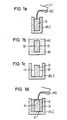
- Figure 1a shows schematically the production of the solid rod from the core glass.
- HFol made of metal, for example made of brass coated with gold
- the rod St is removed from the HFol hollow mold and its surface, at least its peripheral surface, is etched. This can be done, for example, according to FIG. 1b, by immersing the rod St in an etching solution Atl in a container Be, in which it is left for a suitable time.
- the temperature of the HFo2 hollow mold is set so high that the rod St does not shatter.
- the good thermal conductivity of the metal of the HFo2 hollow form, the mass of which should be a multiple of the glass mass, ensures that the jacket glass MG1 cools down so rapidly that it solidifies into glass.
- the finished preform can then be removed from the HFo2 hollow mold.
- a preform was produced from a barium-containing heavy metal fluoride glass for pulling infrared optical fibers.
- a glass composition consisting of ZrHfBaLaAlNa was used. The composition was for the core glass 53 ZrF4. 0 HfF4. 20 BaF2. 4 LaF3. 3 AlF3. 20 NaF and for the jacket glass MGl the composition 40 ZrF4. 13 HfF4. 18 BaF2. 4 LaF3. 3 AlF3. 22 NaF used.
- the numbers in these two expressions are understood as mole percentages. In particular, the core glass contained no Hf afterwards.
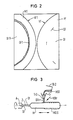
- FIG. 2 sections from cross sections of two preforms VF1 and VF are placed next to one another for comparison.
- the preform VF1 was produced by the method described above, omitting the etching step according to FIG. 1b.
- the rod St1 and the jacket M1 of this preform VF1 one can clearly see a large number of defects consisting of bubbles and crystals.
- the preform VF was produced entirely by the method described above, ie the rod St was etched with ZrOCl2 solution.
- the interface GF between the rod St and the jacket is hardly recognizable.
- barium-containing heavy metal fluoride glasses form a crystalline boundary layer in contact with aqueous acids , which essentially arises from BaF2.
- the fluoride comes from hydrolyzed fluorozirconic acid. If the solution is given zirconyl ions, for example in the form of ZrOCl2. 8 H2O salt, so there is complex formation to oxylfluorozirconic acid. The surface layer, which is disturbed in its composition, then dissolves smoothly, crystals disappear, the surface is leveled.
- the solid rod St made from the core glass is rotated about its horizontal longitudinal axis A and a cladding glass layer is applied to the rotating circumferential surface Of with the aid of a thin glass beam GStr, the rod St and the glass beam GStr being in the axial direction Direction shifted relative to each other.
- the applied molten cladding glass layer is quenched to the glass with a cooling gas flow KStr.
- a next cladding glass layer can be applied in the same way. It is assumed in FIG. 3 that a plurality of cladding glass layers have already been applied and that a further cladding glass layer MGlS is being applied to the already applied cladding M.
- the glass beam GStr which is expediently directed radially to the rod St, can be carried out, for example, with the aid of a funnel Tr which can be displaced axially relative to the rod St, into which the molten jacket glass MG1 produced in a crucible Ti2 is poured and from whose opening TrO the glass beam GStr emerges.
- the flow rate of the glass jet GSTr is metered in such a way that the applied and still molten cladding glass layer MGlS is quenched sufficiently quickly by the cooling gas flow KStr to the glass.
- This can be done by controlling the viscosity of the glass in the funnel Tr.
- the control can take place with the aid of a heating or cooling device, not shown, with which the funnel Tr and its contents are set to a temperature corresponding to the desired viscosity of the glass.
- a fluorine-containing, hydrogen-free molecular gas for example MF3, SF6 or also C2F6, or a chlorinated hydrocarbon, for example CCl4, is added to the cooling gas stream KStr.
- a fluorine-containing, hydrogen-free molecular gas for example MF3, SF6 or also C2F6, or a chlorinated hydrocarbon, for example CCl4
- a chlorinated hydrocarbon for example CCl4
- the solid rod St preheated to protect against cracking is immersed from the core glass in molten jacket glass MG1 in a crucible Ti3, for example made of platinum, and pulled out again.
- the cladding glass layer MGlS which remains adhered to the surface Of of the relatively cool rod St after being pulled out and is at least partially still molten is quenched sufficiently quickly to the glass by means of a cooling gas stream KStr, similar to the method according to FIG.
- the rod St can be rotated about its axis A again.
- a thick one The jacket can be created by multiple dipping and pulling out.
Landscapes
- Chemical & Material Sciences (AREA)
- Engineering & Computer Science (AREA)
- Materials Engineering (AREA)
- Life Sciences & Earth Sciences (AREA)
- Organic Chemistry (AREA)
- Geochemistry & Mineralogy (AREA)
- Manufacturing & Machinery (AREA)
- General Life Sciences & Earth Sciences (AREA)
- General Chemical & Material Sciences (AREA)
- Chemical Kinetics & Catalysis (AREA)
- Physics & Mathematics (AREA)
- Optics & Photonics (AREA)
- Glass Compositions (AREA)
- Manufacture, Treatment Of Glass Fibers (AREA)
- Glass Melting And Manufacturing (AREA)
Abstract
Description
- Die Erfindung betrifft ein Verfahren zur Herstellung einer Vorform zum Ziehen von Glasfasern, insbesondere Infrarot-Lichtwellenleitern für die optische Nachrichtentechnik, nach dem Oberbegriff des Patentanspruchs 1.
- Infrarot-Lichtwellenleiter für die optische Nachrichtentechnik werden aus sauerstofffreien Schwermetallfluorid-Gläsern hergestellt. Netzwerkbildner sind bei diesen Gläsern ZrF₄, HfF₄ oder TlF₄. Als Netzwerkwandler dient BaF₂. Der Schwerpunkt in der Glasstabilität liegt nahe bei der Zusammensetzung Bariumfluorodizirkonat BaZr₂F₁₀. Zur Erhöhung der Glasstabilität wird in der Regel mit dreiwertigen Fluoriden der seltenen Erden, beispielsweise mit LaF₃, GdF₃, YbF₃ oder mit YF₃, AlF₃ dotiert, beispielsweise mit 0 bis 20 Mol-Prozent. Eine typische Glaszusammensetzung ist beispielsweise 57 ZrF₄ . 34 BaF₂ . 5 LaF₃ . 4 AlF₃. Häufig wird zur Unterdrückung der Kristallisationstendenz noch Alkalifluorid, beispielsweise NaF oder LiF anstelle eines Teils des BaF₂ zugesetzt. Charakteristisch ist die generelle Verwendung von BaF₂ als Glasbestandteil.
- Fasern aus Fluoridglas mit Stufenbrechzahlprofil werden heute nahezu ausschließlich nach der Vorform-Methode hergestellt. Dabei wird zunächst ein Glasstab mit einem Kern aus Kernglas und einem Mantel aus Mantelglas präpariert, der dann zur Faser dünn gezogen wird. Typisch für solche Glasstäbe sind ein dem äußeren Manteldurchmesser entsprechender Außendurchmesser von 12 mm, ein Kerndurchmesser von 10 mm, eine Länge von 150 mm und einer Brechzahldifferenz zwischen dem Kernglas und dem Mantelglas von 0,5 bis 1 %. Die aus einem solchen Stab gezogenen Fasern haben typische Außendurchmesser von 0,1 bis 0,2 mm.
- Wegen des Barium-Gehalts der Gläser lassen sich die bekannten CVD-Methoden für die Herstellung von Vorformen aus Quarzglas hier nicht anwenden. Vielmehr geht man über die schmelzflüssige Phase, die dann sehr rasch abgekühlt werden muß, damit das Material glasig erstarrt und Kristallisation vermieden wird. Deshalb wird das Mantelglas zunächst in eine zylindrische Vorform eingegossen, die in der Regel aus goldbeschichtetem Messing gefertigt wird. Durch Rotation der Form gelingt es dann, ein Rohr aus Mantelglas auszuformen, in das anschließend schmelzflüssiges Kernglas eingefüllt werden kann. Dieses Verfahren ist unter dem Begriff "Rotational Casting" bekannt (siehe dazu D.C.Tran, C.F.Fisher, G.H.Sigel Jr.: "Fluoride glass preforms prepared by a rotational casting process", Electronics Lett. 18 (1982) S. 657-658 und US-Patent 4 519 826).
- Häufig findet man allerdings bei derart hergestellten Vorformen Kristalle oder Blasen an der Glasgrenzfläche zwischen Kern und Mantel. Die Ursache dürfte in der Alterung der nicht gekühlten Innenfläche des Mantelglasrohres zu sehen sein, wobei Vorgänge, wie die Aufnahme von Feuchte aus der Atmospäre oder das Abdampfen von Schmelzbestandteilen, beteiligt sind.
- Bei einem zweiten Verfahren wird die kippbare Hohlform zunächst mit schmelzflüssigem Mantelglas gefüllt und kurz darauf durch Umdrehen teilweise wieder entleert. Dies ist möglich, weil das schmelzflüssige Mantelglas vom äußeren Rand nach innen hin erstarrt. Unmittelbar darauf wird schmelzflüssiges Kernglas nachgefüllt. Dieses Verfahren ist unter dem Begriff "Build-in Casting" (siehe S.Mitachi, T.Migashita, T.Kanamori: "Fluoride glass cladded optical fibres for mid-infra-red ray transmission", Electron. Lett. 17 (1981) S. 591-592) bekannt. Bei diesem Verfahren ist die Grenzfläche in der Regel weniger gestört, dafür weicht jedoch der Kerndurchmesser stark von der gewünschten Zylinderform ab.
- Den beiden bekannten Verfahren gemeinsam ist das Prinzip, zunächst ein Rohr aus Mantelglas herzustellen, das dann mit schmelzflüssigem Kernglas aufgefüllt wird. Eine Aufwärmung des Hüllglases durch das Kernglas läßt sich hierbei nicht vermeiden. Dies begünstigt ebenfalls das Kristallwachstum im Mantelglas. Der Wärmewiderstand des Hüllglases ist im Hinblick auf die Herstellung dickerer Vorformen ungünstig, weil dieser die rasche Abkühlung des zentralen Volumens verhindert.
- Aufgabe der Erfindung ist es, ein Verfahren der eingangs genannten Art anzugeben, bei welchem das Problem der raschen Abkühlung eines zentralen Volumens nicht auftritt und mit dem dickere Vorformen problemlos hergestellt werden können.
- Diese Aufgabe wird gemäß dem kennzeichnenden Teil des Patentanspruchs 1 dadurch gelöst, daß ein massiver Stab aus dem Kernglas mit schmelzflüssigem Mantelglas umgeben wird.
- Das erfindungsgemäße Verfahren ist im Hinblick auf die Wärmeabführung wesentlich günstiger, weil die Wärme nicht mehr durch das Hüllglas abgeführt werden muß, sondern direkt in eine umgebende Hohlform aus relativ gut wärmeleitendem Material, in der Regel eine Metallform, abgegeben oder in einen Kühlgasstrom abgeführt werden kann.
- Ein bevorzugtes Verfahren der genannten Art wird nach Anspruch 2 so ausgeführt, daß der massive Stab in eine zylindrische Hohlform größeren Querschnitts aus einem relative gut wärmeleitenden Material eingebracht und der ringförmige Hohlraum zwischen dem Stab und der umgebenden Hohlform mit dem schmelzflüssigen Mantelglas aufgefüllt wird.
- Die Hohlform besteht dabei vorzugsweise gemäß Anspruch 3 aus Metall.
- Bei einer anderen bevorzugten Ausgestaltung des erfindungsgemäßen Verfahrens wird gemäß Anspruch 4 so vorgegangen, daß das schmelzflüssige Mantelglas in einem Strahl auf die Umfangsfläche des um seine Achse rotierenden massiven Stabes aufgegossen wird.
- Dabei ist es vorteilhaft, wenn gemäß Anspruch 5 die auf den massiven Stab aufgegossene schmelzflüssige Mantelglasschicht durch einen Kühlgasstrom abgeschreckt wird.
- Gemäß einer weiteren bevorzugten Ausgestaltung des erfindungsgemäßen Verfahrens wird nach Anspruch 6 so vorgegangen, daß der massive Stab aus dem Kernglas durch Eintauchen in das schmelzflüssige Mantelglas und wieder Herausnehmen des Stabes beschichtet wird.
- Auch bei diesem Verfahren ist es zweckmäßig, wenn nach Anspruch 7 die am wieder herausgezogenen massiven Stab haften gebliebene schmelzflüssige Mantelglasschicht durch einen Kühlgasstrom abgeschreckt wird.
- Zweckmäßigerweise wird einem Kühlgasstrom nach Anspruch 8 ein fluorhaltiges, wasserstofffreies Molekülgas oder/und ein Chlorkohlenwasserstoff zugesetzt.
- Der massive Stab aus dem Kernglas läßt sich auf einfache Weise gemäß Anspruch 9 durch diesen von schmelzflüssigem Kernglas in eine zylindrische Hohlform erzeugen.
- Es wurde festgestellt, daß auch bei dem erfindungsgemäßen Verfahren Glasgrenzflächen zwischen dem Kernglas und dem Mantelglas von schlechter Qualität auftreten. Es wurde gefunden, daß die Ursache dafür in der mangelhaften Oberfläche des eingesetzten massiven Stabes aus dem Kernglas liegt. Eine solche mangelhafte Oberfläche kann herstellungsbedingt sein, beispielsweise wenn der massive Stab aus dem Kernglas durch Gießen des schmelzflüssigen Kernglases in eine zylindrische Hohlform aus Metall erzeugt wird. Durch den Kontakt mit der Metalloberfläche entsteht eine zerklüftete und teilweise kristallisierte Oberfläche.
- Glasgrenzflächen zwischen dem Kernglas und dem Mantelglas von guter Qualität können erfindungsgemäß dadurch erhalten werden, daß nach Anspruch 10 die Oberfläche des massiven Stabes aus dem Kernglas geätzt und erst danach mit schmelzflüssigem Mantelglas umgeben wird.
- Eine nahezu perfekte Glasgrenzfläche zwischen Kernglas und Mantelglas wird erreicht, wenn gemäß Anspruch 11 das Kernglas und das Mantelglas aus einem sauerstofffreien Schwermetall-Fluoridglas bestehen, zumindest das Kernglas Barium enthält und die Oberfläche des aus diesem Kernglas bestehenden massiven Glasstabes mit einer ZrOCl₂-Lösung geätzt wird.
- Wegen der niedrigen Rayleigh-Streuung sowie der hohen IR-Transparenz dieser sauerstofffreien Schwermetall-Fluoridgläser und der nahezu perfekten Glasgrenzfläche zwischen Kern und Mantel, die man mit dem Verfahren nach Anspruch 11 erzielt, dürfen Lichtleitfasern von ca. 2.10⁻² dB/km bei 2550 nm Wellenlänge erwartet werden, deren Herstellung bisher noch nicht gelungen ist (siehe D.C. Tran: "Advances in Mid-Infrared Fibres", Proc. of the 11th Europ. Conf. Opt. Comm., Venice 1985, S. 14-20).
- Bislang wurden nur kurze gute Faserstücke von weniger als 100 m erhalten, weil gehäuft Fehler, wie Blasen oder kristalline Einschlüsse, an der Grenzfläche zwischen Kern und Mantel auftraten.
- Ausführungsbeispiele der Erfindung werden anhand der Figuren in der nun folgenden Beschreibung näher erläutert. Von den Figuren zeigen:
- Figuren 1a bis 1d Verfahrensstufen bei der Herstellung einer Vorform mit Hilfe einer Hohlform,
- Figur 2 Ausschnitte aus vergrößert dargestellten Querschnitten zweier mit Hilfe einer Hohlform hergestellten Vorformen, von denen die linke ohne und die rechte mit Ätzen hergestellt wurde,
- Figur 3 eine schematische Darstellung der Vorformherstellung durch Aufgießen des schmelzflüssigen Mantelglases in einem Strahl auf den rotierenden massiven Stab, und
- Figuren 4a und 4b in schematischer Darstellung zwei Verfahrensstufen bei der Herstellung einer Vorform durch Tauchen des massiven Stabes in schmelzflüssiges Mantelglas.
- Die Figur 1a zeigt schematisch die Herstellung des massiven Stabes aus dem Kernglas. Das in einem Tiegel Til, beispielsweise aus Platin, erzeugte schmelzflüssige Kernglas KGl wird in eine im vertikalen Schnitt gezeigte zylindrische Hohlform HFol aus Metall, beispielsweise aus mit Gold beschichtetem Messing, gegossen, worin es rasch zum massiven Stab St aus Kernglas erstarrt. Dafür sorgt die gute Wärmeleitfähigkeit des Metalls der blockartigen Hohlform HFol.
- Der Stab St wird aus der Hohlform HFol herausgenommen und seine Oberfläche, zumindest seine Umfangsfläche, geätzt. Dies kann beispielsweise nach Figur 1b durch Eintauchen des Stabes St in eine in einem Behälter Be befindliche Ätzlösung Atl geschehen, in der man ihn eine geeignete Zeit lang verbleiben läßt.
- Nach Herausnahme des geätzten Stabes St wird er in eine zylindrische Hohlform HFo2 größeren Querschnitts aus Metall, beispielsweise aus mit Gold beschichtetem Messing, gestellt und in einer Inertgasatmosphäre getrocknet (Fig. 1c).
- Danach wird das in einem Tiegel Ti2, beispielsweise aus Platin, erzeugte schmelzflüssige Mantelglas MGl in den ringförmigen Hohlraum rH zwischen dem Stab St und der umgebenden Hohlform HFo2 gefüllt, sow wie es in der Figur 1d dargestellt ist. Die Temperatur der Hohlform HFo2 wird dazu gerade so hoch eingestellt, daß der Stab St nicht zerspringt. Die gute Wärmeleitfähigkeit des Metalls der Hohlform HFo2, deren Masse ein Vielfaches der Glasmasse sein sollte, sorgt für eine so rasche Abkühlung des Mantelglases MGl, daß dieses zu Glas erstarrt. Danach kann die fertige Vorform aus der Hohlform HFo2 herausgenommen werden.
- Mit dem soeben beschriebenen Verfahren wurde beispielsweise eine Vorform aus einem bariumhaltigen Schwermetall-Fluoridglas zum Ziehen von Infrarot-Lichtwellenleitern hergestellt. Verwendet wurde eine Glaskomposition, die aus ZrHfBaLaAlNa bestand. Für das Kernglas wurde die Zusammensetzung
53 ZrF₄ . 0 HfF₄ . 20 BaF₂ . 4 LaF₃ . 3 AlF₃ . 20 NaF
und für das Mantelglas MGl die Zusammensetzung
40 ZrF₄ . 13 HfF₄ . 18 BaF₂ . 4 LaF₃ . 3 AlF₃ . 22 NaF
verwendet. Die Zahlenangaben in diesen beiden Ausdrücken verstehen sich als Mol-Prozente. Insbesondere enthielt danach das Kernglas kein Hf. - Zum Schmelzen der beiden Gläser in den Tiegeln wurden Temperaturen von 850 bis 900°C verwendet. Die Hohlform, in die das 700° heiße schmelzflüssige Kern- bzw. Mantelglas gegossen wurde, wurde auf 250°C vorgeheizt. Die blockförmigen Hohlformen aus mit Gold beschichtetem Messing hatten etwa die vierfache Masse des in sie zu gießenden schmelzflüssigen Glases. Dadurch wurde erreicht, daß sich das eingegossene schmelzflüssige Glas innerhalb einer Minute von 700°C auf 250°C abkühlt und dadurch zum Glas erstarrt. Die 250°C reichen auch aus, daß beim Schritt nach Fig. 1d der Stab St nicht springt. Zum Ätzen des Stabes St aus dem oben angegebenen Kernglas wurde eine ZrOCl₂-Lösung verwendet. Dadurch wird eine nahezu perfekte Grenzfläche GF zwischen dem aus dem Stab St bestehenden Kern und dem umgebenden Mantel M der Vorform VF erreicht.
- In der Figur 2 sind Ausschnitte aus Querschliffen zweier Vorformen VF1 und VF zum Vergleich nebeneinander gestellt. Die Vorform VF1 wurde nach dem vorstehend beschriebenen Verfahren unter Auslassung des Ätzschrittes nach Fig. 1b hergestellt. An der Grenzfläche zwischen dem Stab St1 und dem Mantel M1 dieser Vorform VF1 erkennt man deutlich eine Vielzahl von Defekten, die aus Blasen und Kristallen bestehen.
- Die Vorform VF wurde vollständig nach dem vorstehend beschriebenen Verfahren hergestellt, d.h. der Stab St wurde mit ZrOCl₂-Lösung geätzt. Die Grenzfläche GF zwischen dem Stab St und dem Mantel ist kaum mehr zu erkennen.
- Das ZrOCl₂-Ätzverfahren für Barium enthaltende Schwermetall-Fluoridgläser ist in der älteren Patentanmeldung P 35 14 082.8 (VPA 85 P 1255 DE) vorgeschlagen worden und sei hier noch einmal kurz erläutert: Bariumhaltige Schwermetall-Fluoridgläser bilden in Kontakt mit wäßrigen Säuren eine kristalline Grenzschicht aus, die im wesentlichen aus BaF₂ entsteht. Dabei stammt das Fluorid aus hydrolisierter Fluorozirkonsäure. Gibt man der Lösung Zirkonylionen, beispielsweise in Form von ZrOCl₂ . 8 H₂O-Salz zu, so erfolgt Komplexbildung zu Oxylfluorozirkonsäure. Die in ihrer Zusammensetzung gestörte Oberflächenschicht löst sich dann glatt auf, Kristalle verschwinden, die Oberfläche wird eingeebnet.
- Bei der in Fig. 3 gezeigten Ausgestaltung des Verfahrens wird der massive Stab St aus dem Kernglas um seine waagerechte Längsachse A rotiert und auf die rotierende Umfangsfläche Of eine Mantelglasschicht mit Hilfe eines dünnen Glasstrahles GStr aufgebracht, wobei der Stab St und der Glasstrahl GStr in axialer Richtung relativ zueinander verschoben. Die aufgebrachte schmelzflüssige Mantelglasschicht wird mit einem Kühlgasstrom KStr zum Glas abgeschreckt. Nach Aufbringen einer solchen Mantelglasschicht kann auf die gleiche Weise eine nächste Mantelglasschicht aufgebracht werden. In der Figur 3 ist angenommen, daß bereits mehrere Mantelglasschichten aufgebracht worden sind und daß gerade eine weitere Mantelglasschicht MGlS auf den bereits aufgebrachten Mantel M aufgebracht wird.
- Der zweckmäßigerweise radial zum Stab St gerichtete Glasstrahl GStr kann beispielsweise mit Hilfe eines relativ zum Stab St axial verschiebbaren Trichters Tr erfolgen, in den das in einem Tiegel Ti2 erzeugte schmelzflüssige Mantelglas MGl geschüttet wird und aus dessen Öffnung TrO der Glasstrahl GStr austritt.
- Die Strömungsgeschwindigkeit des Glasstrahls GSTr wird so dosiert, daß die aufgebrachte und noch schmelzflüssige Mantelglasschicht MGlS durch den Kühlgasstrom KStr hinreichend schnell zum Glas abgeschreckt wird. Dies kann dadurch geschehen, daß die Viskosität des im Trichter Tr befindlichen Glases gesteuert wird. Die Steuerung kann mit Hilfe einer nicht dargestellten Heiz- oder Kühleinrichtung erfolgen, mit welcher der Trichter Tr und sein Inhalt auf eine der gewünschten Viskosität des Glases entsprecchende Temperature eingestellt wird.
- Auch bei diesem Verfahren muß zunächst durch Ätzen des Stabes St für eine einwandfreie Oberfläche Of des Stabes St gesorgt werden.
- Zweckmäßigerweise wird dem Kühlgasstrom KStr ein fluorhaltiges, wasserstofffreies Molekülgas, beispielsweise MF₃, SF₆ oder auch C₂F₆, oder auch ein Chlorkohlenwasserstoff, beispielsweise CCl₄, zugesetzt. Auf diese Weise wird die Restfeuchte in der umgebenden Schutzgasatmosphäre durch chemische Reaktion zu Fluorwasserstoff verringert.
- Bei dem Verfahren nach den Figuren 4a und 4b wird der zum Schutz gegen Zerspringen vorgewärmte massive Stab St aus dem Kernglas in schmelzflüssiges Mantelglas MGl in einem Tiegel Ti3, beispielsweise aus Platin, eingetaucht und wieder herausgezogen. Die an der Oberfläche Of des des relative kühlen Stabes St nach dem Herausziehen haften gebliebene und zumindest teilweise noch schmelzflüssige Mantelglasschicht MGlS wird mittels eines Kühlgasstromes KStr, ähnlich wie beim Verfahren nach Figur 3, hinreichend schnell zum Glas abgeschreckt. Dabei kann, wie in Figur 4b dargestellt, der Stab St wieder um seine Achse A rotiert werden. Für den Kühlgasstrom KStr gilt das gleiche wie beim Verfahren nach Figur 3. Ein dicke rer Mantel kann durch mehrfaches Eintauchen und Herausziehen erzeugt werden.
Claims (11)
Applications Claiming Priority (2)
| Application Number | Priority Date | Filing Date | Title |
|---|---|---|---|
| DE3617716 | 1986-05-27 | ||
| DE3617716 | 1986-05-27 |
Publications (2)
| Publication Number | Publication Date |
|---|---|
| EP0247322A2 true EP0247322A2 (de) | 1987-12-02 |
| EP0247322A3 EP0247322A3 (de) | 1989-02-01 |
Family
ID=6301686
Family Applications (1)
| Application Number | Title | Priority Date | Filing Date |
|---|---|---|---|
| EP87104510A Withdrawn EP0247322A3 (de) | 1986-05-27 | 1987-03-26 | Verfahren zur Herstellung einer Vorform zum Ziehen von optischen Glasfasern |
Country Status (3)
| Country | Link |
|---|---|
| US (1) | US4842627A (de) |
| EP (1) | EP0247322A3 (de) |
| JP (1) | JPS62288127A (de) |
Cited By (3)
| Publication number | Priority date | Publication date | Assignee | Title |
|---|---|---|---|---|
| EP0672628A1 (de) * | 1994-03-16 | 1995-09-20 | CSELT Centro Studi e Laboratori Telecomunicazioni S.p.A. | Verfahren zum Herstellen von monomodalen optischen Fasern aus Fluoridglas |
| EP1184339A3 (de) * | 2000-09-01 | 2002-09-04 | A.R.T.-Photonics GmbH | Optische Faser und Herstellungsverfahren für eine optische Faser |
| CN110316946A (zh) * | 2018-03-28 | 2019-10-11 | 许浒 | 一种整体中空玻璃制作方法及一种整体中空玻璃 |
Families Citing this family (8)
| Publication number | Priority date | Publication date | Assignee | Title |
|---|---|---|---|---|
| US5226940A (en) * | 1987-01-23 | 1993-07-13 | Siemens Aktiengesellschaft | Process for producing optical fibers of high tensile strength |
| NL9000532A (nl) * | 1990-03-08 | 1991-10-01 | Philips Nv | Inrichting voor het opwekken van blauw laserlicht. |
| GB9015090D0 (en) * | 1990-07-09 | 1990-08-29 | British Telecomm | Method for the preparation of halide glass articles |
| USH1259H (en) | 1990-09-28 | 1993-12-07 | Aggarwal Ishwar D | Large fluoride glass preform fabrication |
| US5618326A (en) * | 1991-09-30 | 1997-04-08 | British Telecommunications Public Limited Company | Surface treatment of halide glass articles |
| US8265431B2 (en) * | 2009-11-06 | 2012-09-11 | Baker Hughes Incorporated | Rotated single or multicore optical fiber |
| US9468940B2 (en) | 2012-11-13 | 2016-10-18 | Cnh Industrial Canada, Ltd. | Adjustable orifice valve and calibration method for ammonia applicator system |
| CN110316943B (zh) * | 2018-03-28 | 2021-12-17 | 许浒 | 一种整体真空玻璃制作方法及一种整体真空玻璃 |
Family Cites Families (12)
| Publication number | Priority date | Publication date | Assignee | Title |
|---|---|---|---|---|
| DE2234521A1 (de) * | 1972-07-13 | 1974-01-24 | Siemens Ag | Verfahren zur herstellung einer aus einem kern und einem mantel bestehenden lichtleitfaser |
| DE2614631A1 (de) * | 1976-04-05 | 1977-10-13 | Siemens Ag | Verfahren zur herstellung von gradientenfasern |
| FR2396981A1 (fr) * | 1977-07-05 | 1979-02-02 | Anvar | Fibres optiques en verres fluores et procedes de fabrication de ces fibres |
| DE2853873A1 (de) * | 1978-12-13 | 1980-07-03 | Siemens Ag | Herstellung einer glasfaser hoher zerreissfestigkeit |
| US4248925A (en) * | 1979-06-25 | 1981-02-03 | Corning Glass Works | Encapsulation in glass and glass-ceramic materials |
| US4519826A (en) * | 1983-04-14 | 1985-05-28 | The United States Of America As Represented By The Secretary Of The Navy | Optical fibers having a fluoride glass cladding and method of making |
| FR2545616B1 (fr) * | 1983-05-03 | 1986-10-24 | Commissariat Energie Atomique | Fibres optiques en matiere plastique, notamment multicoeurs, et leur procede de fabrication |
| US4678274A (en) * | 1983-12-27 | 1987-07-07 | Fuller Research Corporation | Low loss cladded optical fibers from halides and process for making same |
| FR2563826B1 (fr) * | 1984-05-07 | 1991-08-30 | Verre Fluore Sa | Procedes de fabrication de fibres et de composants optiques en verres fluores et appareils destines a les mettre en oeuvre |
| US4652288A (en) * | 1984-08-04 | 1987-03-24 | Horiba, Ltd. | Method of producing infrared image guide |
| EP0198189B1 (de) * | 1985-04-18 | 1990-12-05 | Galileo Electro-Optics Corporation | Verfahren zum Entfernen einer Oberflächenschicht von einem Metallfluorid-Glas |
| US4659352A (en) * | 1985-06-21 | 1987-04-21 | Hughes Aircraft Company | Reactive atmosphere processing of heavy-metal fluoride glasses |
-
1987
- 1987-03-26 EP EP87104510A patent/EP0247322A3/de not_active Withdrawn
- 1987-05-22 JP JP62125672A patent/JPS62288127A/ja active Pending
-
1988
- 1988-06-20 US US07/210,192 patent/US4842627A/en not_active Expired - Fee Related
Cited By (6)
| Publication number | Priority date | Publication date | Assignee | Title |
|---|---|---|---|---|
| EP0672628A1 (de) * | 1994-03-16 | 1995-09-20 | CSELT Centro Studi e Laboratori Telecomunicazioni S.p.A. | Verfahren zum Herstellen von monomodalen optischen Fasern aus Fluoridglas |
| US5656056A (en) * | 1994-03-16 | 1997-08-12 | Cselt-Centro Studi E Laboratori Telecomunicazioni S.P.A. | Method for the fabrication of fluoride glass single mode optical fibers with flowing of an etchant through the fiber preform |
| EP1184339A3 (de) * | 2000-09-01 | 2002-09-04 | A.R.T.-Photonics GmbH | Optische Faser und Herstellungsverfahren für eine optische Faser |
| US6564587B2 (en) | 2000-09-01 | 2003-05-20 | Viatcheslav Artiouchenko | Method of producing an optical fiber by gathering material from a molten bath |
| CN110316946A (zh) * | 2018-03-28 | 2019-10-11 | 许浒 | 一种整体中空玻璃制作方法及一种整体中空玻璃 |
| CN110316946B (zh) * | 2018-03-28 | 2021-12-17 | 许浒 | 一种整体中空玻璃制作方法及一种整体中空玻璃 |
Also Published As
| Publication number | Publication date |
|---|---|
| EP0247322A3 (de) | 1989-02-01 |
| US4842627A (en) | 1989-06-27 |
| JPS62288127A (ja) | 1987-12-15 |
Similar Documents
| Publication | Publication Date | Title |
|---|---|---|
| DE2536456C2 (de) | Halbzeug für die Herstellung von Lichtleitfasern und Verfahren zur Herstellung des Halbzeugs | |
| DE2906070C2 (de) | Verfahren zum Herstellen von optischen Wellenleitern | |
| DE69125913T2 (de) | Verfahren zur Herstellung einer polarisationserhaltenden Faser | |
| DE2559895C2 (de) | Verfahren und Einrichtung zum Ziehen von Lichtwellenleitern zur Nachrichtenübertragung | |
| DE69834048T2 (de) | Verfahren und vorrichtung zum herstellen einer vorform für optische fasern | |
| DE2358880C3 (de) | Verfahren zur Herstellung einer Lichtleitfaser | |
| DE2919080A1 (de) | Verfahren zum herstellen einer optischen faser | |
| DE3001792A1 (de) | Verfahren zur herstellung eines mutterstabs fuer die herstellung von optischen fasern | |
| CH656232A5 (de) | Gegen unbefugte anzapfung geschuetzte, strahlungsbestaendige lichtleitfaser. | |
| DE2746949C2 (de) | Verfahren zur Herstellung von Glasfasern mit radialem Brechungsindexgradienten | |
| EP0247322A2 (de) | Verfahren zur Herstellung einer Vorform zum Ziehen von optischen Glasfasern | |
| EP2714603B1 (de) | Verfahren zur herstellung eines halbzeugs zur fertigung einer biegeoptimierten lichtleitfaser | |
| DE2625010C3 (de) | Verfahren zur Herstellung eines Vorformlings für optische Fasern | |
| DE69525222T2 (de) | Verfahren zum Einbringen eines Kernes, Vorrichtung zum Herstellen von optischen Faservorformen und die daraus hergestellten optischen Fasern | |
| DE69118536T2 (de) | Verfahren zur vorbereitung von glaskörpern aus halogeniden | |
| DE69209174T2 (de) | Verfahren zum Herstellen eines Vorform für optische Fasern | |
| DE69306621T2 (de) | Verfahren zur Herstellung eines zylindrischen Glasteiles, insbesondere aus Fluoridglas | |
| DE69715566T2 (de) | Aktive optische Einmoden-Fasern und Verfahren zu deren Herstellung | |
| DE69723475T2 (de) | Verfahren und vorrichtung zur herstellung von optischen fasern aus kern- und mantelglaskörper | |
| DE2915325A1 (de) | Verfahren zur herstellung optischer fasern mit abgestuftem brechungsindex | |
| DE2827303C2 (de) | Verfahren zur Herstellung eines Glasgegenstandes und dessen Anwendung | |
| DE69001282T2 (de) | Verfahren zur kontinuierlichen herstellung eines glasstabes, insbesondere fuer die herstellung von lasermatrizen oder vorformen fuer das ziehen von optischen fasern. | |
| US20240417305A1 (en) | Optical Fiber Manufacturing Using Centrifugal Injection Molding in Microgravity | |
| DE69700707T2 (de) | Verfahren zum Herstellen von Kernbohrungen in durch Giessen hergestellten Vorformen für optische Fasern | |
| DE69309354T2 (de) | Verfahren zum Herstellen einer Vorform für optische Fasern |
Legal Events
| Date | Code | Title | Description |
|---|---|---|---|
| PUAI | Public reference made under article 153(3) epc to a published international application that has entered the european phase |
Free format text: ORIGINAL CODE: 0009012 |
|
| AK | Designated contracting states |
Kind code of ref document: A2 Designated state(s): DE FR GB |
|
| PUAL | Search report despatched |
Free format text: ORIGINAL CODE: 0009013 |
|
| AK | Designated contracting states |
Kind code of ref document: A3 Designated state(s): DE FR GB |
|
| 17P | Request for examination filed |
Effective date: 19890706 |
|
| STAA | Information on the status of an ep patent application or granted ep patent |
Free format text: STATUS: THE APPLICATION IS DEEMED TO BE WITHDRAWN |
|
| 18D | Application deemed to be withdrawn |
Effective date: 19901002 |
|
| RIN1 | Information on inventor provided before grant (corrected) |
Inventor name: SCHOBERTH, ACHIM, DIPL.-ING. Inventor name: SCHNEIDER, HARTMUT, DR.RER.NAT. |