EP0247076B1 - Enthaarungsanordnung - Google Patents
Enthaarungsanordnung Download PDFInfo
- Publication number
- EP0247076B1 EP0247076B1 EP86906354A EP86906354A EP0247076B1 EP 0247076 B1 EP0247076 B1 EP 0247076B1 EP 86906354 A EP86906354 A EP 86906354A EP 86906354 A EP86906354 A EP 86906354A EP 0247076 B1 EP0247076 B1 EP 0247076B1
- Authority
- EP
- European Patent Office
- Prior art keywords
- jaws
- plucking
- arms
- axis
- displacement
- Prior art date
- Legal status (The legal status is an assumption and is not a legal conclusion. Google has not performed a legal analysis and makes no representation as to the accuracy of the status listed.)
- Expired - Lifetime
Links
- 230000035617 depilation Effects 0.000 title abstract 2
- 210000004209 hair Anatomy 0.000 claims abstract description 20
- 238000006073 displacement reaction Methods 0.000 claims abstract description 10
- 238000000926 separation method Methods 0.000 claims 6
- 208000002271 trichotillomania Diseases 0.000 claims 1
- 230000000694 effects Effects 0.000 abstract description 3
- 230000007246 mechanism Effects 0.000 description 5
- 238000005265 energy consumption Methods 0.000 description 2
- 210000000056 organ Anatomy 0.000 description 2
- 238000010276 construction Methods 0.000 description 1
- 230000002951 depilatory effect Effects 0.000 description 1
- 238000012986 modification Methods 0.000 description 1
- 230000004048 modification Effects 0.000 description 1
- 230000001681 protective effect Effects 0.000 description 1
- 230000000717 retained effect Effects 0.000 description 1
Images


Classifications
-
- A—HUMAN NECESSITIES
- A45—HAND OR TRAVELLING ARTICLES
- A45D—HAIRDRESSING OR SHAVING EQUIPMENT; EQUIPMENT FOR COSMETICS OR COSMETIC TREATMENTS, e.g. FOR MANICURING OR PEDICURING
- A45D26/00—Hair-singeing apparatus; Apparatus for removing superfluous hair, e.g. tweezers
- A45D26/0057—Hair-singeing apparatus; Apparatus for removing superfluous hair, e.g. tweezers with multiple elements having a translatory movement parallel to the skin
Definitions
- the present invention relates to hair removal devices which are capable of being held in the hand in order to move them over the skin to remove unwanted hair.
- French patent application 2 307 491 describes an apparatus comprising two pairs of rollers rotating in opposite directions and which are intended to ensure the pulling out of the bristles engaging between them.
- the effectiveness of this device is limited. This is due to the nature of the organs used to pull the hairs. Indeed, the latter are not gripped sufficiently efficiently between the rotating rollers.
- the point where the bristles are actually gripped between the two rollers that is to say the point of contact between them, is necessarily located far behind the corresponding end of the housing of the apparatus.
- depilatory devices which also include rotary bristles for removing hairs, for example the device described in French patent application 2,334,320, as well as that described in French application 2,425,822.
- the efficiency of these devices also leaves something to be desired.
- the cost price of these devices is relatively high, taking into account the presence of the mechanisms necessary to ensure the rotational drive of the members for removing the hairs to be eliminated.
- the aim of the present invention is to produce a small device intended for the same use, but which is designed so as to present optimum efficiency and nevertheless to include a limited cost price.
- this device is essentially characterized in that the tearing members provided therein consist of two jaws arranged one opposite the other and mounted movable in the same plane while being and coupled with a member drive capable of imparting to them an alternative translational movement along an axis parallel to the facing edges of these jaws, while guide means successively ensure the spacing and the tightening of these two jaws during their movement in one direction and in the other, the hairs trapped between the two jaws being torn off under the effect of the transverse displacement of the latter while they are held tight against one another.
- the present apparatus comprises a work head of very simple design and which does not include complicated or expensive mechanisms.
- the movable jaws provided in this working head can be driven in movement by a drive finger animated by an alternative translational movement and this, by a very simple design mechanism of the type of those provided on many electric razors.
- the working head of the present device constitutes in itself one of the objects of the present invention since this head can be adapted on the drive finger provided in certain already existing devices.
- this work head has a very high efficiency. Indeed, the hairs to be plucked can easily engage between the two movable jaws, when the latter are in their spacing position during their displacement in one direction. Then they are strongly pinched between these jaws during their tightening, then torn off under the effect of the traction exerted on them by the jaws during their travel of movement in opposite direction.
- the tearing jaws are formed by the bent ends of two arms, or two pairs of arms, articulated one on the other at an intermediate point of their length, in the manner of the two branches of a collet, and the opposite ends of which are arranged in contact with fixed cams, capable of controlling the movement of the tearing jaws towards and away during the translation of the assembly in one direction and in the other.
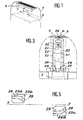
- the device represented in FIGS. 1 to 5 comprises a small box 1 capable of being held in the hand, and inside which is provided an electric motor (not shown) supplied either by a connection to the electrical current distribution sector. , either by built-in batteries or rechargeable batteries.
- this motor imparts an alternating translational movement to a drive arm or finger 3 whose free end is located opposite the 'one of the housing ends 1.
- This comprises two movable jaws 5 tearing arranged one opposite the other.
- These jaws are formed by the bent ends of two arms 20 articulated one on the other, at an intermediate point of their length, in the manner of the two arms of a collet.
- these two arms comprise, on their internal face, a series of knuckles 21 inside which is hinged a hinge pin 22.
- the ends of the latter are engaged in bores 23 formed in the body 24 of the working head of the device.
- the axis 22 is retained in place by the curved ends 25 of a protective grid 26 disposed above the two tearing jaws 5.
- the two articulated arms 20 In their part adjoining the jaws 5, the two articulated arms 20 have a width equal to these. However, in their opposite part these two arms each have a cutout 27 which leaves only an end finger 28 on each of these arms. Fingers are engaged inside grooves 29 provided in the body 24 of the working head and the walls of which are capable of serving as control cams capable of imparting the desired pivoting movements of the arms 20, in one direction and in the other to successively ensure the tightening and the spacing of the lifting jaws 5 during the translational movements of the mobile assembly.
- this drive member carries a transverse tab 30 which is engaged inside notches 31 formed in the articulated arms 20 (see FIG. 4).
- Each groove 29, the walls of which act as control cams, has a first rectilinear part 29a parallel to the XY axis of translation of the movable assembly and a second part 29b, of shorter length, which is bent in the direction of this axis.
- this second part is able to bring the extreme fingers 29 of the two articulated arms closer together and consequently the spacing of the clamping jaws 5. Consequently, the engagement of a bristle to be pulled out P takes place while the fingers 28 of the articulated arms travel, in one direction and in the other, the bent parts 29b of the two grooves 29.
- this first part has a much greater length so that the hairs trapped between the jaws 5 are pulled over a sufficient distance to cause their pulling out.
- the hairs thus plucked out are released when the end fingers 28 return inside the bent parts 29b of the two grooves 29, other bristles then engaging at the same time between the jaws 5 and then being plucked out, and so on. .
- the position of the hinge pin 22, on the two articulated arms 20, is determined so that the latter are able to play the role of levers amplifying the clamping force of the lifting jaws 5 when they are brought together .
- This makes it possible to obtain perfect confinement of the bristles between the two jaws 5. However, this result is obtained with less energy consumption than in the case of the first embodiment described.
- the working head of the present apparatus can be subject to various modifications and other embodiments.
- the grooves 29, serving as control cams for the articulated arms could comprise an inclined part 29b at each end.
- the spacing of the clamping jaws 5 would be effected at each end of the travel of the movable assembly in one direction and in the other, and two successive stripping operations would take place respectively during the movement of the fingers. 28 in one direction, then in the opposite direction.
- control cams could consist of two protrusions against which the two end fingers 28 would be kept applied, for example by means of one or more return springs provided between the arms 20.
- the walls of these protrusions would comprise, as for the grooves 29, a first part of great length parallel to the axis XY, and a second shorter part bent in the direction of this axis. Consequently, the functions provided by these cams would be the same as before.
- the lifting jaws 5 could be carried by two pairs of articulated arms provided at their ends and which would be mounted in the same way so that the arms 20 and also controlled by cams successively ensuring the tightening and spacing of the tearing jaws during the translational movements of the movable assembly in one direction and in the other.
- the apparatus according to the invention has the advantage of being extremely effective. This is due to the very nature of the pinching and lifting bodies. Indeed, these organs are constituted by two jaws which are arranged in the immediate vicinity of the skin, so that the hairs are gripped very close to their roots and not near their end. Consequently, the hairs are plucked out and not broken.
- the effectiveness of the present device is optimum both with regard to the pinching of the hairs to be removed and their pulling out.
- the nature of the movements thus provided also has the advantage that the mechanism of the working head of the present apparatus is particularly simple and inexpensive. Indeed, the jaws of this working head can be very simply driven by a drive finger animated by an alternative translational movement in the manner of the drive fingers existing in certain electric razors. Moreover, this makes it possible to produce the present device from certain already existing elements, initially manufactured for the production of electric razors, only the working head being different. Possibly it would even be possible to make a device that can be used either as an electric razor or an epilator, by providing two separate working heads removably mounted and one of which could serve as a razor and the other as an epilator in accordance with present invention.
- the working head of the present epilating device constitutes in itself one of the objects of the present invention.
- this work head could be marketed independently to be adapted to certain electric shavers or the like.
Landscapes
- Dry Shavers And Clippers (AREA)
- Brushes (AREA)
- Surgical Instruments (AREA)
Claims (6)
Priority Applications (1)
| Application Number | Priority Date | Filing Date | Title |
|---|---|---|---|
| AT86906354T ATE49862T1 (de) | 1985-11-05 | 1986-11-04 | Enthaarungsanordnung. |
Applications Claiming Priority (2)
| Application Number | Priority Date | Filing Date | Title |
|---|---|---|---|
| FR858516350A FR2589338B2 (fr) | 1985-11-05 | 1985-11-05 | Appareil a epiler |
| FR8516350 | 1985-11-05 |
Publications (2)
| Publication Number | Publication Date |
|---|---|
| EP0247076A1 EP0247076A1 (de) | 1987-12-02 |
| EP0247076B1 true EP0247076B1 (de) | 1990-01-31 |
Family
ID=9324495
Family Applications (1)
| Application Number | Title | Priority Date | Filing Date |
|---|---|---|---|
| EP86906354A Expired - Lifetime EP0247076B1 (de) | 1985-11-05 | 1986-11-04 | Enthaarungsanordnung |
Country Status (5)
| Country | Link |
|---|---|
| US (1) | US4800881A (de) |
| EP (1) | EP0247076B1 (de) |
| DE (1) | DE3668540D1 (de) |
| FR (1) | FR2589338B2 (de) |
| WO (1) | WO1987002556A1 (de) |
Families Citing this family (6)
| Publication number | Priority date | Publication date | Assignee | Title |
|---|---|---|---|---|
| DE3922949C1 (de) * | 1989-07-12 | 1990-09-27 | Braun Ag, 6000 Frankfurt, De | |
| BE1004386A3 (nl) * | 1990-08-20 | 1992-11-10 | S Mcd Murphy & Partners Ltd | Epileerapparaat. |
| DE3939874A1 (de) * | 1989-12-02 | 1991-06-06 | Klaus Dipl Ing Becker | Haarentfernungsvorrichtung |
| DE4023252A1 (de) * | 1990-07-21 | 1992-01-23 | Braun Ag | Zupfkopf fuer motorisch betriebene epiliergeraete |
| US5234441A (en) * | 1992-01-06 | 1993-08-10 | Braun Aktiengesellschaft | Epilating appliance |
| CN101204267B (zh) * | 2006-12-20 | 2011-05-18 | 游图明 | 一种拔毛器 |
Family Cites Families (17)
| Publication number | Priority date | Publication date | Assignee | Title |
|---|---|---|---|---|
| US1667170A (en) * | 1924-04-15 | 1928-04-24 | Segal Samuel | Tweezers |
| US2025006A (en) * | 1932-09-02 | 1935-12-17 | Vivian Beauty Shoppe Inc | Hair pulling device |
| US1991816A (en) * | 1934-02-24 | 1935-02-19 | Us Appliance Corp | Tweezers |
| US2123870A (en) * | 1934-09-24 | 1938-07-19 | Wehmer Bruno | Eyebrow plucker |
| US2272053A (en) * | 1938-01-07 | 1942-02-03 | James D Altemus | Electric shaving implement |
| BE474252A (de) * | 1943-04-06 | |||
| US2413998A (en) * | 1945-08-18 | 1947-01-07 | Scott Horatio John | Depilator |
| US2936768A (en) * | 1958-01-02 | 1960-05-17 | Edwin H Chamberlain | Power operated manicuring device |
| US3911530A (en) * | 1973-02-05 | 1975-10-14 | James S Kalfsbeek | System and method for removing feathers from ducks and other fowl |
| FR2215914A1 (de) * | 1973-02-07 | 1974-08-30 | Warde Jacques | |
| GB1448872A (en) * | 1973-07-02 | 1976-09-08 | Blackburne R M | Electric dry shavers |
| FR2307491A1 (fr) * | 1975-04-15 | 1976-11-12 | Dzikowski Francis | Appareil a epiler automatique |
| GB1508528A (en) * | 1975-12-09 | 1978-04-26 | Daar Y | Apparatus for plucking hair from skin |
| US4171701A (en) * | 1977-07-01 | 1979-10-23 | Clairol Incorporated | Tweezer |
| NL7805230A (nl) * | 1978-05-16 | 1979-11-20 | Philips Nv | Epileerapparaat. |
| FR2556939B1 (fr) * | 1983-12-22 | 1987-10-23 | Jean Alazet | Appareil a epiler |
| US4700476A (en) * | 1984-11-02 | 1987-10-20 | Remington Products, Inc. | Shaver for a medical treatment preparation procedure |
-
1985
- 1985-11-05 FR FR858516350A patent/FR2589338B2/fr not_active Expired - Lifetime
-
1986
- 1986-11-04 DE DE8686906354T patent/DE3668540D1/de not_active Expired - Fee Related
- 1986-11-04 WO PCT/FR1986/000374 patent/WO1987002556A1/fr not_active Ceased
- 1986-11-04 US US07/076,168 patent/US4800881A/en not_active Expired - Fee Related
- 1986-11-04 EP EP86906354A patent/EP0247076B1/de not_active Expired - Lifetime
Also Published As
| Publication number | Publication date |
|---|---|
| EP0247076A1 (de) | 1987-12-02 |
| DE3668540D1 (de) | 1990-03-08 |
| FR2589338B2 (fr) | 1991-11-08 |
| US4800881A (en) | 1989-01-31 |
| WO1987002556A1 (fr) | 1987-05-07 |
| FR2589338A2 (fr) | 1987-05-07 |
Similar Documents
| Publication | Publication Date | Title |
|---|---|---|
| EP0272269B1 (de) | Epiliergerät | |
| EP0147285B1 (de) | Haarentfernungsgerät | |
| EP0328426B1 (de) | Enthaarungsgerät | |
| EP0373032B1 (de) | Enthaarungsgerät | |
| EP0364321B1 (de) | Gerät zum Enthaaren | |
| EP0394105B1 (de) | Enthaarungsgerät | |
| FR2745992A1 (fr) | Dispositif d'epilation mecanique anti-douleur et procede associe | |
| EP0247076B1 (de) | Enthaarungsanordnung | |
| EP0383684B1 (de) | Haarentfernungsgerät | |
| FR2586538A1 (fr) | Appareil a epiler. | |
| EP1289391B1 (de) | Epilationsapparat mit auf einer kette angeordneten pinzetten | |
| EP1289390B1 (de) | Epilationsapparat mit pinzetten | |
| EP2462832A1 (de) | Enthaarungsgerät mit Präzisionskopf | |
| FR2678822A1 (fr) | Appareil a epiler la peau des humains. | |
| FR2800584A1 (fr) | Accessoire d'exfoliation pour un appareil a epiler | |
| FR2684856A1 (fr) | Appareil d'epilation a elements de serrage par paires. | |
| FR2656993A2 (fr) | Appareil a epiler. | |
| FR2674733A1 (fr) | Epilateur. | |
| EP2903475B1 (de) | Isostatische epilationsvorrichtung mit translatorisch bewegbaren pinzetten | |
| FR2661079A1 (fr) | Appareil pour pratiquer l'epilation. |
Legal Events
| Date | Code | Title | Description |
|---|---|---|---|
| PUAI | Public reference made under article 153(3) epc to a published international application that has entered the european phase |
Free format text: ORIGINAL CODE: 0009012 |
|
| 17P | Request for examination filed |
Effective date: 19870626 |
|
| AK | Designated contracting states |
Kind code of ref document: A1 Designated state(s): AT BE CH DE GB IT LI LU NL SE |
|
| 111L | Licence recorded |
Free format text: 0100 NORCOUTE NOUVELLE DISTRIBUTION FRANCAISE |
|
| 17Q | First examination report despatched |
Effective date: 19890418 |
|
| ITF | It: translation for a ep patent filed | ||
| GRAA | (expected) grant |
Free format text: ORIGINAL CODE: 0009210 |
|
| AK | Designated contracting states |
Kind code of ref document: B1 Designated state(s): AT BE CH DE GB IT LI LU NL SE |
|
| REF | Corresponds to: |
Ref document number: 49862 Country of ref document: AT Date of ref document: 19900215 Kind code of ref document: T |
|
| GBT | Gb: translation of ep patent filed (gb section 77(6)(a)/1977) | ||
| REF | Corresponds to: |
Ref document number: 3668540 Country of ref document: DE Date of ref document: 19900308 |
|
| REG | Reference to a national code |
Ref country code: CH Ref legal event code: PLI Owner name: NORCOUTE NOUVELLE DISTRIBUTION FRANCAISE |
|
| PLBE | No opposition filed within time limit |
Free format text: ORIGINAL CODE: 0009261 |
|
| STAA | Information on the status of an ep patent application or granted ep patent |
Free format text: STATUS: NO OPPOSITION FILED WITHIN TIME LIMIT |
|
| 26N | No opposition filed | ||
| ITTA | It: last paid annual fee | ||
| PGFP | Annual fee paid to national office [announced via postgrant information from national office to epo] |
Ref country code: LU Payment date: 19931116 Year of fee payment: 8 |
|
| PGFP | Annual fee paid to national office [announced via postgrant information from national office to epo] |
Ref country code: GB Payment date: 19931117 Year of fee payment: 8 |
|
| PGFP | Annual fee paid to national office [announced via postgrant information from national office to epo] |
Ref country code: SE Payment date: 19931122 Year of fee payment: 8 |
|
| PGFP | Annual fee paid to national office [announced via postgrant information from national office to epo] |
Ref country code: CH Payment date: 19931126 Year of fee payment: 8 |
|
| PGFP | Annual fee paid to national office [announced via postgrant information from national office to epo] |
Ref country code: NL Payment date: 19931130 Year of fee payment: 8 Ref country code: AT Payment date: 19931130 Year of fee payment: 8 |
|
| PGFP | Annual fee paid to national office [announced via postgrant information from national office to epo] |
Ref country code: BE Payment date: 19931201 Year of fee payment: 8 |
|
| EPTA | Lu: last paid annual fee | ||
| PGFP | Annual fee paid to national office [announced via postgrant information from national office to epo] |
Ref country code: DE Payment date: 19940131 Year of fee payment: 8 |
|
| PG25 | Lapsed in a contracting state [announced via postgrant information from national office to epo] |
Ref country code: LU Free format text: LAPSE BECAUSE OF NON-PAYMENT OF DUE FEES Effective date: 19941104 Ref country code: GB Effective date: 19941104 Ref country code: AT Effective date: 19941104 |
|
| PG25 | Lapsed in a contracting state [announced via postgrant information from national office to epo] |
Ref country code: SE Effective date: 19941105 |
|
| PG25 | Lapsed in a contracting state [announced via postgrant information from national office to epo] |
Ref country code: LI Effective date: 19941130 Ref country code: CH Effective date: 19941130 Ref country code: BE Effective date: 19941130 |
|
| EAL | Se: european patent in force in sweden |
Ref document number: 86906354.5 |
|
| BERE | Be: lapsed |
Owner name: PILUS Effective date: 19941130 |
|
| PG25 | Lapsed in a contracting state [announced via postgrant information from national office to epo] |
Ref country code: NL Effective date: 19950601 |
|
| GBPC | Gb: european patent ceased through non-payment of renewal fee |
Effective date: 19941104 |
|
| NLV4 | Nl: lapsed or anulled due to non-payment of the annual fee | ||
| REG | Reference to a national code |
Ref country code: CH Ref legal event code: PL |
|
| PG25 | Lapsed in a contracting state [announced via postgrant information from national office to epo] |
Ref country code: DE Effective date: 19950801 |
|
| EUG | Se: european patent has lapsed |
Ref document number: 86906354.5 |
|
| PG25 | Lapsed in a contracting state [announced via postgrant information from national office to epo] |
Ref country code: IT Free format text: LAPSE BECAUSE OF NON-PAYMENT OF DUE FEES;WARNING: LAPSES OF ITALIAN PATENTS WITH EFFECTIVE DATE BEFORE 2007 MAY HAVE OCCURRED AT ANY TIME BEFORE 2007. THE CORRECT EFFECTIVE DATE MAY BE DIFFERENT FROM THE ONE RECORDED. Effective date: 20051104 |