EP0247003B1 - Dispositif de sécurité contre le vol d'objets - Google Patents
Dispositif de sécurité contre le vol d'objets Download PDFInfo
- Publication number
- EP0247003B1 EP0247003B1 EP87810306A EP87810306A EP0247003B1 EP 0247003 B1 EP0247003 B1 EP 0247003B1 EP 87810306 A EP87810306 A EP 87810306A EP 87810306 A EP87810306 A EP 87810306A EP 0247003 B1 EP0247003 B1 EP 0247003B1
- Authority
- EP
- European Patent Office
- Prior art keywords
- housing
- plate
- disposed
- permanent magnet
- reed
- Prior art date
- Legal status (The legal status is an assumption and is not a legal conclusion. Google has not performed a legal analysis and makes no representation as to the accuracy of the status listed.)
- Expired - Lifetime
Links
Images
Classifications
-
- G—PHYSICS
- G08—SIGNALLING
- G08B—SIGNALLING SYSTEMS, e.g. PERSONAL CALLING SYSTEMS; ORDER TELEGRAPHS; ALARM SYSTEMS
- G08B13/00—Burglar, theft or intruder alarms
- G08B13/02—Mechanical actuation
- G08B13/14—Mechanical actuation by lifting or attempted removal of hand-portable articles
- G08B13/149—Mechanical actuation by lifting or attempted removal of hand-portable articles with electric, magnetic, capacitive switch actuation
-
- G—PHYSICS
- G08—SIGNALLING
- G08B—SIGNALLING SYSTEMS, e.g. PERSONAL CALLING SYSTEMS; ORDER TELEGRAPHS; ALARM SYSTEMS
- G08B29/00—Checking or monitoring of signalling or alarm systems; Prevention or correction of operating errors, e.g. preventing unauthorised operation
- G08B29/02—Monitoring continuously signalling or alarm systems
- G08B29/04—Monitoring of the detection circuits
- G08B29/046—Monitoring of the detection circuits prevention of tampering with detection circuits
Definitions
- the invention relates to a device according to the preamble of claim 1.
- Such a device is known from DE-C-1108111.
- This known direction uses a stationary protective tube contact arrangement which consists of at least two protective tube contacts, also known as reed contacts, which are mounted next to one another.
- Permanent magnets which are individually assigned to these protective tube contacts and are attached to the object to be secured are likewise mounted next to one another and have opposite polarity, so that the device cannot be sabotaged by means of an external magnet.
- This known device has the disadvantage that permanent magnets have to be attached to the object to be protected, so that this object is defaced or changed.
- the invention has for its object to avoid the shortcomings of the known device in a device of the type mentioned.
- the device according to the invention offers various advantages. It is flat, compact, light and has a small volume and high operational and sabotage security. Vibrations and small movements on the monitored object, such as those caused by observers or caused by ventilation, cannot trigger an alarm. No components of the device have to be attached to the monitored object, so that this object is not defaced or changed.
- the device according to the invention does not require a voltage source and it can be combined with a transmitter for wireless transmission of alarms.
- a voltage source and it can be combined with a transmitter for wireless transmission of alarms.
- protective tube contacts and permanent magnets as components, the device is protected against dusting, dirt, aggressive gases and aging.
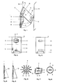
- the device according to FIG. 1 has a housing 1 to which a plate 10 is fastened so that it can be rotated on one side in such a way that the friction along the axis of rotation A is as small as possible.
- a thin plastic film connects the housing 1 to the plate 10.
- the attachment of the plate 10 to the housing 1 can also consist of threads or a tape.
- the housing 1 with the plate 10 and a painting 14 are attached to a wall 16.
- a protective tube contact 7 is arranged, which is surrounded by protective tube contacts 3, 4, 5, 6.
- two thermowell contacts 8, 9 and a permanent magnet 2 are arranged.
- a permanent magnet 15 is attached to the wall 16 behind the protective tube contact 9.
- a permanent magnet 13 is assigned to the protective tube contact 7, a permanent magnet 12 to the protective tube contact 8 and a permanent magnet 11 to the permanent magnet 2.
- the plate 10 is repelled by the housing 1 with the same polarity of the permanent magnets 2.11 until the painting 10 mm away from the housing is touched by the plate 10. The distance of the painting 14 from the housing 1 is thus detected by the plate 10. If the painting 14 is removed from the housing 1 by a certain maximum distance, the plate 10 assumes the position shown in FIG. 5 and the magnetic field of the permanent magnet 13 on the protective tube contact 7 becomes so weak that this contact opens and an alarm is triggered. If the painting 14 is brought to a certain minimum distance from the housing 1, for example by touching or pushing, the plate 10 assumes the position shown in FIG. 4 and the magnetic field of the permanent magnet 12 on the protective tube contact 8 becomes so strong that this contact closes and an alarm is triggered.
- the permanent magnet 13 and the protective tube contact 7 are to be arranged as close as possible to the axis of rotation A of the plate 10 and the permanent magnet 12 and the protective tube contact 8 as far as possible from the axis of rotation A in order to ensure reliable functioning of the device despite the relatively weak magnetic fields of the permanent magnets 12, 13 ensure walking. In this way, different above-mentioned maximum and minimum distances can be selected depending on the magnetic field strength of the permanent magnets 12, 13. If the arrangement is maliciously torn off the wall 16, the protective tube contact 9 opens, which is kept closed by the permanent magnet 15, and a sabotage alarm is triggered.
- the protective tube contacts 3, 4, 5, 6 surrounding the protective tube contact 7 protect the protective tube contact 7 from external magnetic fields supplied from outside for sabotage of the device by at least one of them
- Thermowell contacts close when an external magnetic field is applied and a sabotage alarm is triggered.
- the arrangement of the protective tube contacts 3, 4, 5, 6 can be star-shaped, rectangular and offset or circular, as shown in FIGS. 6, 7 and 8, in which the number of these contacts is greater than 4.
- FIG. 2 shows the view of the assembled housing 1 with the protective tube contacts 3 to 9 and the permanent magnet 2.
- FIG. 3 shows the view of the equipped plate 10 with the permanent magnets 11 to 13.
- the device according to the invention can also be implemented without the permanent magnet 12 and protective tube contact 8.
- the distance between the protective tube contact 5 and the protective tube contact 7 must be selected such that when the plate 10 approaches the housing 1 according to FIG. 4, the protective tube contact 5 is closed by the permanent magnet 13.
Landscapes
- Physics & Mathematics (AREA)
- General Physics & Mathematics (AREA)
- Engineering & Computer Science (AREA)
- Computer Security & Cryptography (AREA)
- Burglar Alarm Systems (AREA)
- Transition And Organic Metals Composition Catalysts For Addition Polymerization (AREA)
- Medicines Containing Material From Animals Or Micro-Organisms (AREA)
Claims (9)
- Dispositif de sécurité à l'égard du vol d'objets, par exemple des tableaux ou des étuis pour papiers-valeur, utilisant des contacts scellés et des aimants permanents, caractérisé en ce qu'il comprend un boîtier (1) disposé de façon fixe et recevant des contacts scellés (3-9), de même qu'un aimant permanent (2), une plaque (10) fixée au boîtier (1) d'une façon tournante seulement dans un sens et sur laquelle plusieurs aimants permanents (11-13) sont disposés, la plaque étant repoussée par deux (2,11) desdits aimants permanents de façon telle qu'elle touche l'objet (14), et caractérisé de plus en ce que deux contacts scellés (7,8 ou 7,5) sont disposés dans le boîtier (1), tandis qu'au moins un aimant permanent (13 ou 12,13) est disposé sur la plaque (10) de façon tel le qu'une alarme soit enclenchée lorsque l'objet (14) se trouve à une certaine distance minimale ou maximale du boîtier (1).
- Dispositif selon la revendication 1, caractérisé en ce que, dans la partie supérieure du boîtier (1), une pluralité de contacts scellés (3-6) entoure un contact scellé (7) de façon à protéger celui-ci de champs magnétiques appliqués de l'extérieur dans un but de sabotage.
- Dispositif selon la revendication 2, caractérisé en ce que les contacts scellés de ladite pluralité (3-6) sont disposés et décalés autour dudit contact scellé central (7) selon une disposition en forme de cercle, en forme d'étoile ou en forme de carré.
- Dispositif selon la revendication 1, caractérisé en ce que la plaque (10) est fixée au boîtier (1) de façon tournante seulement dans un sens d'une manière telle que le frottement le long de l'axe de pivotement (A) soit aussi petit que possible.
- Dispositif selon la revendication 4, caractérisé en ce que la fixation de la plaque (10) au boîtier consiste en une mince feuille ou bande, ou en un fil.
- Dispositif selon la revendication 1, caractérisé en ce qu'un contact scellé (9) se trouve actionné par un aimant permanent (15) fixé à l'endroit où se trouve le dispositif, de façon qu'une alarme de sabotage soit enclenchée lors d'un arrachage brutal du boîtier de l'endroit où il est fixé.
- Dispositif selon la revendication 1, caractérisé en ce que deux contacts scellés (7,8) sont disposés dans le boîtier (1) tandis que deux aimants permanents (12,13) sont disposés sur la plaque (10), de manière qu'une aI arme soit enclenchée lorsque l'objet se trouve à une distance minimale ou maximale du boîtier (1).
- Dispositif selon la revendication 1, caractérisé en ce que deux contacts scellés (7,5) sont disposés dans le boîtier (1), tandis qu'un aimant permanent (13) est disposé sur la plaque (10), de façon telle qu'une alarme soit enclenchée lorsque l'objet se trouve à une distance minimale ou maximale du boîtier (1).
- Dispositif selon la revendication 7, caractérisé en ce qu'un contact scellé (7) dans la partie supérieure du boîtier (1) et un aimant permanent (13) sur la partie supérieure de la plaque (10) sont disposés le plus près possible de l'axe de pivotement (A) de la plaque (10), un contact scellé (8) dans la partie inférieure du boîtier (1) et un aimant permanent (12) étant disposés aussi loin que possible dudit axe de pivotement.
Priority Applications (1)
| Application Number | Priority Date | Filing Date | Title |
|---|---|---|---|
| AT87810306T ATE66080T1 (de) | 1986-05-21 | 1987-05-20 | Vorrichtung zur sicherung gegen diebstahl von gegenstaenden. |
Applications Claiming Priority (2)
| Application Number | Priority Date | Filing Date | Title |
|---|---|---|---|
| CH2051/86 | 1986-05-21 | ||
| CH205186 | 1986-05-21 |
Publications (2)
| Publication Number | Publication Date |
|---|---|
| EP0247003A1 EP0247003A1 (fr) | 1987-11-25 |
| EP0247003B1 true EP0247003B1 (fr) | 1991-08-07 |
Family
ID=4224776
Family Applications (1)
| Application Number | Title | Priority Date | Filing Date |
|---|---|---|---|
| EP87810306A Expired - Lifetime EP0247003B1 (fr) | 1986-05-21 | 1987-05-20 | Dispositif de sécurité contre le vol d'objets |
Country Status (6)
| Country | Link |
|---|---|
| EP (1) | EP0247003B1 (fr) |
| AT (1) | ATE66080T1 (fr) |
| DE (1) | DE3771929D1 (fr) |
| DK (1) | DK165030C (fr) |
| FI (1) | FI85777C (fr) |
| NO (1) | NO168394C (fr) |
Family Cites Families (2)
| Publication number | Priority date | Publication date | Assignee | Title |
|---|---|---|---|---|
| DE1108111B (de) * | 1960-05-20 | 1961-05-31 | Siemens Ag | Anordnung zur Sicherung gegen Diebstahl |
| NL300473A (fr) * | 1963-04-17 |
-
1987
- 1987-05-19 NO NO872092A patent/NO168394C/no not_active IP Right Cessation
- 1987-05-20 DK DK256687A patent/DK165030C/da not_active IP Right Cessation
- 1987-05-20 AT AT87810306T patent/ATE66080T1/de not_active IP Right Cessation
- 1987-05-20 EP EP87810306A patent/EP0247003B1/fr not_active Expired - Lifetime
- 1987-05-20 DE DE8787810306T patent/DE3771929D1/de not_active Expired - Lifetime
- 1987-05-21 FI FI872229A patent/FI85777C/fi not_active IP Right Cessation
Also Published As
| Publication number | Publication date |
|---|---|
| ATE66080T1 (de) | 1991-08-15 |
| DE3771929D1 (de) | 1991-09-12 |
| FI85777C (fi) | 1992-05-25 |
| FI872229A0 (fi) | 1987-05-21 |
| NO168394C (no) | 1992-02-12 |
| NO168394B (no) | 1991-11-04 |
| FI872229A7 (fi) | 1987-11-22 |
| DK165030C (da) | 1993-02-08 |
| DK165030B (da) | 1992-09-28 |
| NO872092L (no) | 1987-11-23 |
| NO872092D0 (no) | 1987-05-19 |
| FI85777B (fi) | 1992-02-14 |
| EP0247003A1 (fr) | 1987-11-25 |
| DK256687A (da) | 1987-11-22 |
| DK256687D0 (da) | 1987-05-20 |
Similar Documents
| Publication | Publication Date | Title |
|---|---|---|
| AT507762B1 (de) | Einrichtung zum schützen von geldausgabeautomaten | |
| DE69701994T2 (de) | Tierhalsband | |
| DE69501732T2 (de) | Alarmetikett | |
| DE202005021530U1 (de) | Halterung für mindestens einen Gegenstand mit Diebstahlwarnvorrichtung | |
| DE2514330A1 (de) | Alarmsystem | |
| DE2526171A1 (de) | Vorrichtung zur raumsicherung | |
| DE69605687T2 (de) | Alarmetikett | |
| EP0247003B1 (fr) | Dispositif de sécurité contre le vol d'objets | |
| US4117478A (en) | Variable character display device | |
| EP0814451B1 (fr) | Dispositif de support d'une cassette pour prix ou informations | |
| DE1773797C3 (de) | Durch Vlbration betätigbarer elektrischer Schalter, insbesondere für Einbruchmeldeanlagen | |
| DE2520929A1 (de) | Ionisations-feuerdetektor | |
| DE2732262A1 (de) | Gesichertes schutzgehaeuse fuer eine alarmschallquelle | |
| DE3518029C2 (de) | Diebstahlsicherung zur Einschränkung der unbefugten Entfernung von Datenträgern, insbesondere von Kompakt-Schallplatten, aus einem Gehäuse | |
| EP0353646A2 (fr) | Détecteur passif infra-rouge d'intrusion pour surveillance de locaux | |
| DE8029809U1 (de) | Haltevorrichtung für elektrische Geräte, insbesondere für Einbruchdetektoren | |
| EP1224640A1 (fr) | Element de securite antivol pour la securite antivol electronique d'articles | |
| CH673721A5 (en) | Anti-theft security tag - uses cooperating contacts and magnets to monitor distance of protected item to activate alarm | |
| DE9115266U1 (de) | Öffnungsmelder | |
| DE3119112A1 (de) | Einrichtung zur sicherung von gegenstaenden gegen unbefugtes mitnehmen | |
| EP1977403B1 (fr) | Élément de protection de marchandises pour système de protection acoustomagnétique | |
| EP0968489A1 (fr) | Bande pour preparer des elements de protection pour la protection electronique d'articles | |
| CH635933A5 (de) | Fehleraufspuergeraet zur verwendung an vorrichtungen, bei deren betrieb schwingungen erzeugt werden. | |
| DE8530957U1 (de) | Magnetfeldbetätigte Sicherheits-Kontakteinrichtung | |
| DE2623136C2 (de) | Melde- und/oder Alarmvorrichtung |
Legal Events
| Date | Code | Title | Description |
|---|---|---|---|
| PUAI | Public reference made under article 153(3) epc to a published international application that has entered the european phase |
Free format text: ORIGINAL CODE: 0009012 |
|
| AK | Designated contracting states |
Kind code of ref document: A1 Designated state(s): AT BE CH DE FR GB IT LI NL SE |
|
| 17P | Request for examination filed |
Effective date: 19880519 |
|
| 17Q | First examination report despatched |
Effective date: 19901207 |
|
| GRAA | (expected) grant |
Free format text: ORIGINAL CODE: 0009210 |
|
| AK | Designated contracting states |
Kind code of ref document: B1 Designated state(s): AT BE CH DE FR GB IT LI NL SE |
|
| REF | Corresponds to: |
Ref document number: 66080 Country of ref document: AT Date of ref document: 19910815 Kind code of ref document: T |
|
| REF | Corresponds to: |
Ref document number: 3771929 Country of ref document: DE Date of ref document: 19910912 |
|
| ITF | It: translation for a ep patent filed | ||
| ET | Fr: translation filed | ||
| GBT | Gb: translation of ep patent filed (gb section 77(6)(a)/1977) | ||
| PLBE | No opposition filed within time limit |
Free format text: ORIGINAL CODE: 0009261 |
|
| STAA | Information on the status of an ep patent application or granted ep patent |
Free format text: STATUS: NO OPPOSITION FILED WITHIN TIME LIMIT |
|
| 26N | No opposition filed | ||
| EAL | Se: european patent in force in sweden |
Ref document number: 87810306.8 |
|
| REG | Reference to a national code |
Ref country code: GB Ref legal event code: IF02 |
|
| PGFP | Annual fee paid to national office [announced via postgrant information from national office to epo] |
Ref country code: AT Payment date: 20020409 Year of fee payment: 16 |
|
| PGFP | Annual fee paid to national office [announced via postgrant information from national office to epo] |
Ref country code: FR Payment date: 20020411 Year of fee payment: 16 |
|
| PGFP | Annual fee paid to national office [announced via postgrant information from national office to epo] |
Ref country code: NL Payment date: 20020415 Year of fee payment: 16 |
|
| PGFP | Annual fee paid to national office [announced via postgrant information from national office to epo] |
Ref country code: GB Payment date: 20020417 Year of fee payment: 16 |
|
| PGFP | Annual fee paid to national office [announced via postgrant information from national office to epo] |
Ref country code: SE Payment date: 20020418 Year of fee payment: 16 |
|
| PGFP | Annual fee paid to national office [announced via postgrant information from national office to epo] |
Ref country code: BE Payment date: 20020508 Year of fee payment: 16 |
|
| PG25 | Lapsed in a contracting state [announced via postgrant information from national office to epo] |
Ref country code: GB Free format text: LAPSE BECAUSE OF NON-PAYMENT OF DUE FEES Effective date: 20030520 Ref country code: AT Free format text: LAPSE BECAUSE OF NON-PAYMENT OF DUE FEES Effective date: 20030520 |
|
| PG25 | Lapsed in a contracting state [announced via postgrant information from national office to epo] |
Ref country code: SE Free format text: LAPSE BECAUSE OF NON-PAYMENT OF DUE FEES Effective date: 20030521 |
|
| PG25 | Lapsed in a contracting state [announced via postgrant information from national office to epo] |
Ref country code: BE Free format text: LAPSE BECAUSE OF NON-PAYMENT OF DUE FEES Effective date: 20030531 |
|
| BERE | Be: lapsed |
Owner name: *SECURITON A.G. Effective date: 20030531 |
|
| PG25 | Lapsed in a contracting state [announced via postgrant information from national office to epo] |
Ref country code: NL Free format text: LAPSE BECAUSE OF NON-PAYMENT OF DUE FEES Effective date: 20031201 |
|
| EUG | Se: european patent has lapsed | ||
| GBPC | Gb: european patent ceased through non-payment of renewal fee |
Effective date: 20030520 |
|
| PG25 | Lapsed in a contracting state [announced via postgrant information from national office to epo] |
Ref country code: FR Free format text: LAPSE BECAUSE OF NON-PAYMENT OF DUE FEES Effective date: 20040130 |
|
| NLV4 | Nl: lapsed or anulled due to non-payment of the annual fee |
Effective date: 20031201 |
|
| REG | Reference to a national code |
Ref country code: FR Ref legal event code: ST |
|
| PG25 | Lapsed in a contracting state [announced via postgrant information from national office to epo] |
Ref country code: IT Free format text: LAPSE BECAUSE OF NON-PAYMENT OF DUE FEES;WARNING: LAPSES OF ITALIAN PATENTS WITH EFFECTIVE DATE BEFORE 2007 MAY HAVE OCCURRED AT ANY TIME BEFORE 2007. THE CORRECT EFFECTIVE DATE MAY BE DIFFERENT FROM THE ONE RECORDED. Effective date: 20050520 |
|
| PGFP | Annual fee paid to national office [announced via postgrant information from national office to epo] |
Ref country code: DE Payment date: 20060419 Year of fee payment: 20 |
|
| PGFP | Annual fee paid to national office [announced via postgrant information from national office to epo] |
Ref country code: CH Payment date: 20060508 Year of fee payment: 20 |
|
| REG | Reference to a national code |
Ref country code: CH Ref legal event code: PL |