EP0247003B1 - Security device against the theft of objects - Google Patents
Security device against the theft of objects Download PDFInfo
- Publication number
- EP0247003B1 EP0247003B1 EP87810306A EP87810306A EP0247003B1 EP 0247003 B1 EP0247003 B1 EP 0247003B1 EP 87810306 A EP87810306 A EP 87810306A EP 87810306 A EP87810306 A EP 87810306A EP 0247003 B1 EP0247003 B1 EP 0247003B1
- Authority
- EP
- European Patent Office
- Prior art keywords
- housing
- plate
- disposed
- permanent magnet
- reed
- Prior art date
- Legal status (The legal status is an assumption and is not a legal conclusion. Google has not performed a legal analysis and makes no representation as to the accuracy of the status listed.)
- Expired - Lifetime
Links
Images
Classifications
-
- G—PHYSICS
- G08—SIGNALLING
- G08B—SIGNALLING SYSTEMS, e.g. PERSONAL CALLING SYSTEMS; ORDER TELEGRAPHS; ALARM SYSTEMS
- G08B13/00—Burglar, theft or intruder alarms
- G08B13/02—Mechanical actuation
- G08B13/14—Mechanical actuation by lifting or attempted removal of hand-portable articles
- G08B13/149—Mechanical actuation by lifting or attempted removal of hand-portable articles with electric, magnetic, capacitive switch actuation
-
- G—PHYSICS
- G08—SIGNALLING
- G08B—SIGNALLING SYSTEMS, e.g. PERSONAL CALLING SYSTEMS; ORDER TELEGRAPHS; ALARM SYSTEMS
- G08B29/00—Checking or monitoring of signalling or alarm systems; Prevention or correction of operating errors, e.g. preventing unauthorised operation
- G08B29/02—Monitoring continuously signalling or alarm systems
- G08B29/04—Monitoring of the detection circuits
- G08B29/046—Monitoring of the detection circuits prevention of tampering with detection circuits
Definitions
- the invention relates to a device according to the preamble of claim 1.
- Such a device is known from DE-C-1108111.
- This known direction uses a stationary protective tube contact arrangement which consists of at least two protective tube contacts, also known as reed contacts, which are mounted next to one another.
- Permanent magnets which are individually assigned to these protective tube contacts and are attached to the object to be secured are likewise mounted next to one another and have opposite polarity, so that the device cannot be sabotaged by means of an external magnet.
- This known device has the disadvantage that permanent magnets have to be attached to the object to be protected, so that this object is defaced or changed.
- the invention has for its object to avoid the shortcomings of the known device in a device of the type mentioned.
- the device according to the invention offers various advantages. It is flat, compact, light and has a small volume and high operational and sabotage security. Vibrations and small movements on the monitored object, such as those caused by observers or caused by ventilation, cannot trigger an alarm. No components of the device have to be attached to the monitored object, so that this object is not defaced or changed.
- the device according to the invention does not require a voltage source and it can be combined with a transmitter for wireless transmission of alarms.
- a voltage source and it can be combined with a transmitter for wireless transmission of alarms.
- protective tube contacts and permanent magnets as components, the device is protected against dusting, dirt, aggressive gases and aging.
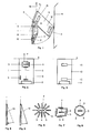
- the device according to FIG. 1 has a housing 1 to which a plate 10 is fastened so that it can be rotated on one side in such a way that the friction along the axis of rotation A is as small as possible.
- a thin plastic film connects the housing 1 to the plate 10.
- the attachment of the plate 10 to the housing 1 can also consist of threads or a tape.
- the housing 1 with the plate 10 and a painting 14 are attached to a wall 16.
- a protective tube contact 7 is arranged, which is surrounded by protective tube contacts 3, 4, 5, 6.
- two thermowell contacts 8, 9 and a permanent magnet 2 are arranged.
- a permanent magnet 15 is attached to the wall 16 behind the protective tube contact 9.
- a permanent magnet 13 is assigned to the protective tube contact 7, a permanent magnet 12 to the protective tube contact 8 and a permanent magnet 11 to the permanent magnet 2.
- the plate 10 is repelled by the housing 1 with the same polarity of the permanent magnets 2.11 until the painting 10 mm away from the housing is touched by the plate 10. The distance of the painting 14 from the housing 1 is thus detected by the plate 10. If the painting 14 is removed from the housing 1 by a certain maximum distance, the plate 10 assumes the position shown in FIG. 5 and the magnetic field of the permanent magnet 13 on the protective tube contact 7 becomes so weak that this contact opens and an alarm is triggered. If the painting 14 is brought to a certain minimum distance from the housing 1, for example by touching or pushing, the plate 10 assumes the position shown in FIG. 4 and the magnetic field of the permanent magnet 12 on the protective tube contact 8 becomes so strong that this contact closes and an alarm is triggered.
- the permanent magnet 13 and the protective tube contact 7 are to be arranged as close as possible to the axis of rotation A of the plate 10 and the permanent magnet 12 and the protective tube contact 8 as far as possible from the axis of rotation A in order to ensure reliable functioning of the device despite the relatively weak magnetic fields of the permanent magnets 12, 13 ensure walking. In this way, different above-mentioned maximum and minimum distances can be selected depending on the magnetic field strength of the permanent magnets 12, 13. If the arrangement is maliciously torn off the wall 16, the protective tube contact 9 opens, which is kept closed by the permanent magnet 15, and a sabotage alarm is triggered.
- the protective tube contacts 3, 4, 5, 6 surrounding the protective tube contact 7 protect the protective tube contact 7 from external magnetic fields supplied from outside for sabotage of the device by at least one of them
- Thermowell contacts close when an external magnetic field is applied and a sabotage alarm is triggered.
- the arrangement of the protective tube contacts 3, 4, 5, 6 can be star-shaped, rectangular and offset or circular, as shown in FIGS. 6, 7 and 8, in which the number of these contacts is greater than 4.
- FIG. 2 shows the view of the assembled housing 1 with the protective tube contacts 3 to 9 and the permanent magnet 2.
- FIG. 3 shows the view of the equipped plate 10 with the permanent magnets 11 to 13.
- the device according to the invention can also be implemented without the permanent magnet 12 and protective tube contact 8.
- the distance between the protective tube contact 5 and the protective tube contact 7 must be selected such that when the plate 10 approaches the housing 1 according to FIG. 4, the protective tube contact 5 is closed by the permanent magnet 13.
Landscapes
- Physics & Mathematics (AREA)
- General Physics & Mathematics (AREA)
- Engineering & Computer Science (AREA)
- Computer Security & Cryptography (AREA)
- Burglar Alarm Systems (AREA)
- Transition And Organic Metals Composition Catalysts For Addition Polymerization (AREA)
- Medicines Containing Material From Animals Or Micro-Organisms (AREA)
Abstract
Description
Die Erfindung betrifft eine Vorrichtung gemäss dem Oberbegriff des Anspruches 1.The invention relates to a device according to the preamble of
Eine solche Vorrichtung ist aus DE-C-1108111 bekannt. Diese bekannte richtung verwendet eine ortsfest angebrachte Schutzrohrkontakte-Anordnung, welche aus mindestens zwei nebeneinander montierten Schutzrohrkontakten, auch Reed-Kontakte genannt, besteht. Diesen Schutzrohrkontakten einzeln zugeordnete, am zu sichernden Gegenstand angebrachte Dauermagnete sind ebenfalls nebeneinander montiert und entgegengesetzt gepolt, so dass die Vorrichtung nicht mittels eines Fremdmagneten sabotiert werden kann. Diese bekannte Vorrichtung weist den Nachteil auf, dass am zu schützenden Gegenstand Dauermagnete befestigt werden müssen, so dass dieser Gegenstand verunstaltet oder verändert wird.Such a device is known from DE-C-1108111. This known direction uses a stationary protective tube contact arrangement which consists of at least two protective tube contacts, also known as reed contacts, which are mounted next to one another. Permanent magnets which are individually assigned to these protective tube contacts and are attached to the object to be secured are likewise mounted next to one another and have opposite polarity, so that the device cannot be sabotaged by means of an external magnet. This known device has the disadvantage that permanent magnets have to be attached to the object to be protected, so that this object is defaced or changed.
Der Erfindung liegt die Aufgabe zugrunde bei einer Vorrichtung der eingangs genannten Art die Mängel der bekannten Vorrichtung zu vermeiden.The invention has for its object to avoid the shortcomings of the known device in a device of the type mentioned.
Diese Aufgabe wird durch die im Anspruch 1 gekennzeichneten Merkmale gelöst.This object is achieved by the features characterized in
Die erfindungsgemässe Vorrichtung bietet verschiedene Vorteile. Sie ist flach, kompakt, leicht und weist ein kleines Volumen und eine hohe Betriebs- und Sabotagesicherheit auf. Vibrationen und kleine Bewegungen am überwachten Gegenstand, wie sie durch Beobachter verursacht werden oder beim Lüften entstehen, können keinen Alarm auslösen. Auf dem überwachten Gegenstand müssen keine Bauelemente der Vorrichtung befestigt werden, so dass dieser Gegenstand nicht verunstaltet oder verändert wird.The device according to the invention offers various advantages. It is flat, compact, light and has a small volume and high operational and sabotage security. Vibrations and small movements on the monitored object, such as those caused by observers or caused by ventilation, cannot trigger an alarm. No components of the device have to be attached to the monitored object, so that this object is not defaced or changed.
Ferner benötigt die erfindungsgemässe Vorrichtung keine Spannungsquelle und sie kann mit einem Sender für eine drahtlose Uebermittlung von Alarmen kombiniert werden. Durch die Verwendung von Schutzrohrkontakten und Dauermagneten als Bauelemente ist die Vorrichtung gegen Verstäubung, Verschmutzung, agressive Gase und Alterung geschützt.Furthermore, the device according to the invention does not require a voltage source and it can be combined with a transmitter for wireless transmission of alarms. By using protective tube contacts and permanent magnets as components, the device is protected against dusting, dirt, aggressive gases and aging.
Vorteilhafte Ausgestaltungen der Erfindung sind in den Unteransprüchen gekennzeichnet.Advantageous embodiments of the invention are characterized in the subclaims.
Die Erfindung wird nachstehend an Hand der in der Zeichnung dargestellten Ausführungsbeispiele erläutert. In dieser zeigen:
- Fig. 1
- die erfindungsgemässe Vorrichtung
- Fig. 2
- Ansicht des bestückten Gehäuses
- Fig. 3
- Ansicht der bestückten Platte
- Fig. 4 und 5
- zwei Positionen der Platte, bei welchen ein Alarm ausgelöst wird.
- Fig. 6 bis 8
- verschiedene Anordnungen der Schutzrohrkontakte
- Fig. 1
- the device according to the invention
- Fig. 2
- View of the assembled housing
- Fig. 3
- View of the assembled plate
- 4 and 5
- two positions of the plate at which an alarm is triggered.
- 6 to 8
- different arrangements of the thermowell contacts
Die Vorrichtung gemäss Fig. 1 weist ein Gehäuse 1 auf, an welchem eine Platte 10 einseitig drehbar derart befestigt ist, dass die Reibung längs der Drehachse A möglichst klein ist. Zu diesem Zweck verbindet eine dünne, nicht gezeigte Kunststoff-Folie das Gehäuse 1 mit der Platte 10. Die Befestigung der Platte 10 am Gehäuse 1 kann auch aus Fäden oder einem Band bestehen. Das Gehäuse 1 mit der Platte 10 und ein Gemälde 14 sind an einer Wand 16 befestigt. Im oberen Teil des Gehäuses 1 ist ein Schutzrohrkontakt 7 angeordnet, welcher von Schutzrohrkontakten 3,4,5,6 umschlossen ist. Im unteren Teil des Gehäuses 1 sind zwei Schutzrohrkontakte 8,9 und ein Dauermagnet 2 angeordnet.The device according to FIG. 1 has a
Ein Dauermagnet 15 ist an der Wand 16 hinter dem Schutzrohrkontakt 9 befestigt. Auf der Platte 10 ist ein Dauermagnet 13 dem Schutzrohrkontakt 7, ein Dauermagnet 12 dem Schutzrohrkontakt 8 und ein Dauermagnet 11 dem Dauermagneten 2 zugeordnet.A
Die Platte 10 wird durch die gleichgepolten Dauermagnete 2,11 vom Gehäuse 1 soweit abgestossen, bis das um einige Milimeter vom Gehäuse entfernte Gemälde von der Platte 10 berührt wird. Somit wird der Abstand des Gemäldes 14 vom Gehäuse 1 durch die Platte 10 erfasst. Wird das Gemälde 14 auf eine bestimmte maximale Distanz vom Gehäuse 1 entfernt, nimmt die Platte 10 die in Fig. 5 dargestellte Lage an und das Magnetfeld des Dauermagneten 13 am Schutzrohrkontakt 7 wird so schwach, dass dieser Kontakt öffnet und ein Alarm ausgelöst wird. Wird das Gemälde 14 auf eine bestimmte minimale Distanz vom Gehäuse 1, z.B. durch Berühren oder Stossen gebracht, nimmt die Platte 10 die in Fig. 4 dargestellte Lage an und das Magnetfeld des Dauermagneten 12 am Schutzrohrkontakt 8 wird so stark, dass dieser Kontakt schliesst und ein Alarm ausgelöst wird. Der Dauermagnet 13 und der Schutzrohrkontakt 7 sind möglichst nahe an der Drehachse A der Platte 10 und der Dauermagnet 12 und der Schutzrohrkontakt 8 möglichst weit von der Drehachse A anzuordnen, um trotz der relativ schwachen Magnetfelder der Dauermagnete 12,13 ein zuverlässiges Funktionnieren der Vorrichtung zu gehwährleisten. Auf diese Weise können in Abhängikeit von der Magnetfeldstärke der Dauermagnete 12,13 verschiedene obgenannte maximale und minimale Distanzen gewählt werden. Bei böswilligem Abreissen der Anordnung von der Wand 16 öffnet der Schutzrohrkontakt 9, welcher durch den Dauermagneten 15 geschlossen gehalten wird und ein Sabotage-Alarm wird ausgelöst. Die den Schutzrohrkontakt 7 umschliessenden Schutzrohrkontakte 3,4,5,6 schützen den Schutzrohrkontakt 7 vor fremden, von aussen für Sabotage der Vorrichtung zugeführten Magnetfeldern, indem mindestens ein von diesen Schutzrohrkontakten schliesst, wenn ein fremdes Magnetfeld zugeführt wird und ein Sabotage-Alarm wird ausgelöst. Die Anordnung der Schutzrohrkontakte 3,4,5,6 kann sternförmig, rechteckig und versetzt oder kreisförmig sein, wie dies in den Fig. 6,7 und 8 gezeigt ist, in welchen die Anzahl dieser Kontakte grösser als 4 ist.The
Die Fig. 2 zeigt die Ansicht des bestückten Gehäuses 1 mit den Schutzrohrkontakten 3 bis 9 und dem Dauermagneten 2. Die Fig. 3 zeigt die Ansicht der bestückten Platte 10 mit den Dauermagneten 11 bis 13.FIG. 2 shows the view of the assembled
Gemäss einer Variante des beschriebenen Ausführungsbeispiels kann die erfindungsgemässe Vorrichtung auch ohne den Dauermagneten 12 und Schutzrohrkontakt 8 ausgeführt werden. In diesem Fall muss der Abstand des Schutzrohrkontaktes 5 vom Schutzrohrkontakt 7 so gewählt werden, dass beim Annähern der Platte 10 an das Gehäuse 1 gemäss Fig. 4 der Schutzrohrkontakt 5 durch den Dauermagenten 13 geschlossen wird.According to a variant of the exemplary embodiment described, the device according to the invention can also be implemented without the
Claims (9)
- Security device against the theft of objects, e.g. paintings and safes, using reed relays and permanent magnets, characterized by a permanently mounted housing (1) to incorporate reed relays (3 to 9) and a permanent magnet (2), a plate (10) attached pivotably on one side of the housing (1) on which plate are disposed several permanent magnets (11 to 13), the plate being repelled by two (2, 11) of the said permanent magnets in such a way that it comes into contact with the object (14), also characterized in that two reed relays (7, 8 or 7, 5) are disposed in the housing (1) and at least one permanent magnet (13 or 12, 13) is disposed on the plate (10) in such a way that if the object (14) is at a given minimum or maximum distance from the housing (1), an alarm is set off.
- The device of claim 1, characterized in that in the upper part of the housing (1) a number of the reed relays (3 to 6) encircle one reed relay (7) in such a way that they screen this reed relay (7) from magnetic fields introduced from the outside for the purposes of sabotage.
- The device of claim 2, characterized in that the said number of reed relays (3 to 6) is disposed around the reed relay (7) circularly, radially or squarely and set back.
- The arrangement of claim 1, characterized in that the plate (10) is pivotably fixed on one side of the housing (1) such that the friction along the pivot axis (A) is as small as possible.
- The device of claim 4, characterized in that the plate (10) is affixed to the housing by a thin film, threads or a tape.
- The device of claim 1, characterized in that if the permanently mounted housing is maliciously torn away, a reed relay (9) is activated by a permanent magnet (15) located at that point so that a sabotage alarm is set off.
- The device of claim 1, characterized in that two reed relays (7, 8) are disposed in the housing (1) and two permanent magnets (12, 13) are disposed on the plate (10) in such a way that if the object is at a given minimum or maximum distance from the housing (1) an alarm is set off.
- The device of claim 1, characterized in that two reed relays (7, 5) are disposed in the housing (1) and one permanent magnet (13) is disposed on the plate (10) in such a way that if the object is at a given minimum or maximum distance from the housing (1) an alarm is set off.
- The device of claim 7, characterized in that one reed relay (7) is disposed in the upper part of the housing (1) and one permanent magnet (13) is disposed on the upper part of the plate (10) as near as possible to the pivot axis (A) of the plate (10) and one reed relay (8) is disposed in the lower part of the housing (1) and one permanent magnet (12) is disposed as far as possible from the said pivot axis.
Priority Applications (1)
| Application Number | Priority Date | Filing Date | Title |
|---|---|---|---|
| AT87810306T ATE66080T1 (en) | 1986-05-21 | 1987-05-20 | ANTI-THEFT PROTECTION DEVICE. |
Applications Claiming Priority (2)
| Application Number | Priority Date | Filing Date | Title |
|---|---|---|---|
| CH2051/86 | 1986-05-21 | ||
| CH205186 | 1986-05-21 |
Publications (2)
| Publication Number | Publication Date |
|---|---|
| EP0247003A1 EP0247003A1 (en) | 1987-11-25 |
| EP0247003B1 true EP0247003B1 (en) | 1991-08-07 |
Family
ID=4224776
Family Applications (1)
| Application Number | Title | Priority Date | Filing Date |
|---|---|---|---|
| EP87810306A Expired - Lifetime EP0247003B1 (en) | 1986-05-21 | 1987-05-20 | Security device against the theft of objects |
Country Status (6)
| Country | Link |
|---|---|
| EP (1) | EP0247003B1 (en) |
| AT (1) | ATE66080T1 (en) |
| DE (1) | DE3771929D1 (en) |
| DK (1) | DK165030C (en) |
| FI (1) | FI85777C (en) |
| NO (1) | NO168394C (en) |
Family Cites Families (2)
| Publication number | Priority date | Publication date | Assignee | Title |
|---|---|---|---|---|
| DE1108111B (en) * | 1960-05-20 | 1961-05-31 | Siemens Ag | Arrangement to secure against theft |
| NL300473A (en) * | 1963-04-17 |
-
1987
- 1987-05-19 NO NO872092A patent/NO168394C/en not_active IP Right Cessation
- 1987-05-20 DK DK256687A patent/DK165030C/en not_active IP Right Cessation
- 1987-05-20 AT AT87810306T patent/ATE66080T1/en not_active IP Right Cessation
- 1987-05-20 EP EP87810306A patent/EP0247003B1/en not_active Expired - Lifetime
- 1987-05-20 DE DE8787810306T patent/DE3771929D1/en not_active Expired - Lifetime
- 1987-05-21 FI FI872229A patent/FI85777C/en not_active IP Right Cessation
Also Published As
| Publication number | Publication date |
|---|---|
| ATE66080T1 (en) | 1991-08-15 |
| DE3771929D1 (en) | 1991-09-12 |
| FI85777C (en) | 1992-05-25 |
| FI872229A0 (en) | 1987-05-21 |
| NO168394C (en) | 1992-02-12 |
| NO168394B (en) | 1991-11-04 |
| FI872229A7 (en) | 1987-11-22 |
| DK165030C (en) | 1993-02-08 |
| DK165030B (en) | 1992-09-28 |
| NO872092L (en) | 1987-11-23 |
| NO872092D0 (en) | 1987-05-19 |
| FI85777B (en) | 1992-02-14 |
| EP0247003A1 (en) | 1987-11-25 |
| DK256687A (en) | 1987-11-22 |
| DK256687D0 (en) | 1987-05-20 |
Similar Documents
| Publication | Publication Date | Title |
|---|---|---|
| AT507762B1 (en) | DEVICE FOR PROTECTING MONEY OUTPUT AUTOMATES | |
| DE69701994T2 (en) | ANIMAL COLLAR | |
| DE69501732T2 (en) | ALARM LABEL | |
| DE202005021530U1 (en) | Holder for at least one article with anti-theft device | |
| DE2514330A1 (en) | ALARM SYSTEM | |
| DE2526171A1 (en) | DEVICE FOR ROOM SECURITY | |
| DE69605687T2 (en) | ALARM LABEL | |
| EP0247003B1 (en) | Security device against the theft of objects | |
| US4117478A (en) | Variable character display device | |
| EP0814451B1 (en) | Device to support a price or information cassette | |
| DE1773797C3 (en) | Electrical switch that can be operated by means of bration, especially for burglar alarm systems | |
| DE2520929A1 (en) | IONIZATION FIRE DETECTOR | |
| DE2732262A1 (en) | SECURED PROTECTIVE HOUSING FOR AN ALARM SOUND SOURCE | |
| DE3518029C2 (en) | Anti-theft device to restrict the unauthorized removal of data carriers, in particular compact records, from a housing | |
| EP0353646A2 (en) | Passive infrared intrusion detector for monitoring spaces | |
| DE8029809U1 (en) | Holding device for electrical devices, in particular for intrusion detectors | |
| EP1224640A1 (en) | Securing element for electronically securing articles | |
| CH673721A5 (en) | Anti-theft security tag - uses cooperating contacts and magnets to monitor distance of protected item to activate alarm | |
| DE9115266U1 (en) | Opening detector | |
| DE3119112A1 (en) | Device for protecting objects against unauthorised taking away | |
| EP1977403B1 (en) | Goods security element for acousto-magnetic security systems | |
| EP0968489A1 (en) | Strip for preparing safety elements for electronic protection of goods | |
| CH635933A5 (en) | ERROR DETECTOR FOR USE ON DEVICES WHICH OPERATE VIBRATIONS ARE GENERATED. | |
| DE8530957U1 (en) | Magnetic field operated safety contact device | |
| DE2623136C2 (en) | Signaling and / or alarm device |
Legal Events
| Date | Code | Title | Description |
|---|---|---|---|
| PUAI | Public reference made under article 153(3) epc to a published international application that has entered the european phase |
Free format text: ORIGINAL CODE: 0009012 |
|
| AK | Designated contracting states |
Kind code of ref document: A1 Designated state(s): AT BE CH DE FR GB IT LI NL SE |
|
| 17P | Request for examination filed |
Effective date: 19880519 |
|
| 17Q | First examination report despatched |
Effective date: 19901207 |
|
| GRAA | (expected) grant |
Free format text: ORIGINAL CODE: 0009210 |
|
| AK | Designated contracting states |
Kind code of ref document: B1 Designated state(s): AT BE CH DE FR GB IT LI NL SE |
|
| REF | Corresponds to: |
Ref document number: 66080 Country of ref document: AT Date of ref document: 19910815 Kind code of ref document: T |
|
| REF | Corresponds to: |
Ref document number: 3771929 Country of ref document: DE Date of ref document: 19910912 |
|
| ITF | It: translation for a ep patent filed | ||
| ET | Fr: translation filed | ||
| GBT | Gb: translation of ep patent filed (gb section 77(6)(a)/1977) | ||
| PLBE | No opposition filed within time limit |
Free format text: ORIGINAL CODE: 0009261 |
|
| STAA | Information on the status of an ep patent application or granted ep patent |
Free format text: STATUS: NO OPPOSITION FILED WITHIN TIME LIMIT |
|
| 26N | No opposition filed | ||
| EAL | Se: european patent in force in sweden |
Ref document number: 87810306.8 |
|
| REG | Reference to a national code |
Ref country code: GB Ref legal event code: IF02 |
|
| PGFP | Annual fee paid to national office [announced via postgrant information from national office to epo] |
Ref country code: AT Payment date: 20020409 Year of fee payment: 16 |
|
| PGFP | Annual fee paid to national office [announced via postgrant information from national office to epo] |
Ref country code: FR Payment date: 20020411 Year of fee payment: 16 |
|
| PGFP | Annual fee paid to national office [announced via postgrant information from national office to epo] |
Ref country code: NL Payment date: 20020415 Year of fee payment: 16 |
|
| PGFP | Annual fee paid to national office [announced via postgrant information from national office to epo] |
Ref country code: GB Payment date: 20020417 Year of fee payment: 16 |
|
| PGFP | Annual fee paid to national office [announced via postgrant information from national office to epo] |
Ref country code: SE Payment date: 20020418 Year of fee payment: 16 |
|
| PGFP | Annual fee paid to national office [announced via postgrant information from national office to epo] |
Ref country code: BE Payment date: 20020508 Year of fee payment: 16 |
|
| PG25 | Lapsed in a contracting state [announced via postgrant information from national office to epo] |
Ref country code: GB Free format text: LAPSE BECAUSE OF NON-PAYMENT OF DUE FEES Effective date: 20030520 Ref country code: AT Free format text: LAPSE BECAUSE OF NON-PAYMENT OF DUE FEES Effective date: 20030520 |
|
| PG25 | Lapsed in a contracting state [announced via postgrant information from national office to epo] |
Ref country code: SE Free format text: LAPSE BECAUSE OF NON-PAYMENT OF DUE FEES Effective date: 20030521 |
|
| PG25 | Lapsed in a contracting state [announced via postgrant information from national office to epo] |
Ref country code: BE Free format text: LAPSE BECAUSE OF NON-PAYMENT OF DUE FEES Effective date: 20030531 |
|
| BERE | Be: lapsed |
Owner name: *SECURITON A.G. Effective date: 20030531 |
|
| PG25 | Lapsed in a contracting state [announced via postgrant information from national office to epo] |
Ref country code: NL Free format text: LAPSE BECAUSE OF NON-PAYMENT OF DUE FEES Effective date: 20031201 |
|
| EUG | Se: european patent has lapsed | ||
| GBPC | Gb: european patent ceased through non-payment of renewal fee |
Effective date: 20030520 |
|
| PG25 | Lapsed in a contracting state [announced via postgrant information from national office to epo] |
Ref country code: FR Free format text: LAPSE BECAUSE OF NON-PAYMENT OF DUE FEES Effective date: 20040130 |
|
| NLV4 | Nl: lapsed or anulled due to non-payment of the annual fee |
Effective date: 20031201 |
|
| REG | Reference to a national code |
Ref country code: FR Ref legal event code: ST |
|
| PG25 | Lapsed in a contracting state [announced via postgrant information from national office to epo] |
Ref country code: IT Free format text: LAPSE BECAUSE OF NON-PAYMENT OF DUE FEES;WARNING: LAPSES OF ITALIAN PATENTS WITH EFFECTIVE DATE BEFORE 2007 MAY HAVE OCCURRED AT ANY TIME BEFORE 2007. THE CORRECT EFFECTIVE DATE MAY BE DIFFERENT FROM THE ONE RECORDED. Effective date: 20050520 |
|
| PGFP | Annual fee paid to national office [announced via postgrant information from national office to epo] |
Ref country code: DE Payment date: 20060419 Year of fee payment: 20 |
|
| PGFP | Annual fee paid to national office [announced via postgrant information from national office to epo] |
Ref country code: CH Payment date: 20060508 Year of fee payment: 20 |
|
| REG | Reference to a national code |
Ref country code: CH Ref legal event code: PL |