EP0246838A2 - Presswerkzeug-Aufbau zur Verwendung bei der Herstellung einer Schattenmaske für eine Farbkathodenstrahlröhre - Google Patents
Presswerkzeug-Aufbau zur Verwendung bei der Herstellung einer Schattenmaske für eine Farbkathodenstrahlröhre Download PDFInfo
- Publication number
- EP0246838A2 EP0246838A2 EP87304379A EP87304379A EP0246838A2 EP 0246838 A2 EP0246838 A2 EP 0246838A2 EP 87304379 A EP87304379 A EP 87304379A EP 87304379 A EP87304379 A EP 87304379A EP 0246838 A2 EP0246838 A2 EP 0246838A2
- Authority
- EP
- European Patent Office
- Prior art keywords
- mould
- mould assembly
- parts
- die
- assembly
- Prior art date
- Legal status (The legal status is an assumption and is not a legal conclusion. Google has not performed a legal analysis and makes no representation as to the accuracy of the status listed.)
- Granted
Links
- 238000004519 manufacturing process Methods 0.000 title description 4
- 239000002184 metal Substances 0.000 claims description 15
- 229910052751 metal Inorganic materials 0.000 claims description 15
- 238000003825 pressing Methods 0.000 claims description 10
- 238000010438 heat treatment Methods 0.000 claims description 9
- 238000000034 method Methods 0.000 claims description 8
- 239000011810 insulating material Substances 0.000 claims description 6
- 239000011491 glass wool Substances 0.000 claims description 3
- 239000010425 asbestos Substances 0.000 claims description 2
- 239000007799 cork Substances 0.000 claims description 2
- 239000010445 mica Substances 0.000 claims description 2
- 229910052618 mica group Inorganic materials 0.000 claims description 2
- 239000011490 mineral wool Substances 0.000 claims description 2
- 229910052895 riebeckite Inorganic materials 0.000 claims description 2
- 238000000465 moulding Methods 0.000 claims 1
- 238000009413 insulation Methods 0.000 abstract description 2
- 230000005540 biological transmission Effects 0.000 abstract 1
- 238000012546 transfer Methods 0.000 description 5
- 239000000463 material Substances 0.000 description 3
- 239000011295 pitch Substances 0.000 description 3
- 125000006850 spacer group Chemical group 0.000 description 3
- XEEYBQQBJWHFJM-UHFFFAOYSA-N Iron Chemical compound [Fe] XEEYBQQBJWHFJM-UHFFFAOYSA-N 0.000 description 2
- 229910001030 Iron–nickel alloy Inorganic materials 0.000 description 2
- PXHVJJICTQNCMI-UHFFFAOYSA-N Nickel Chemical compound [Ni] PXHVJJICTQNCMI-UHFFFAOYSA-N 0.000 description 2
- 229910045601 alloy Inorganic materials 0.000 description 2
- 239000000956 alloy Substances 0.000 description 2
- 230000015572 biosynthetic process Effects 0.000 description 2
- 238000002474 experimental method Methods 0.000 description 2
- 229910001374 Invar Inorganic materials 0.000 description 1
- 238000000137 annealing Methods 0.000 description 1
- 238000009826 distribution Methods 0.000 description 1
- 239000012530 fluid Substances 0.000 description 1
- 229910052742 iron Inorganic materials 0.000 description 1
- 238000012986 modification Methods 0.000 description 1
- 230000004048 modification Effects 0.000 description 1
- 229910052759 nickel Inorganic materials 0.000 description 1
- 238000012545 processing Methods 0.000 description 1
- 238000007493 shaping process Methods 0.000 description 1
Images
Classifications
-
- B—PERFORMING OPERATIONS; TRANSPORTING
- B21—MECHANICAL METAL-WORKING WITHOUT ESSENTIALLY REMOVING MATERIAL; PUNCHING METAL
- B21D—WORKING OR PROCESSING OF SHEET METAL OR METAL TUBES, RODS OR PROFILES WITHOUT ESSENTIALLY REMOVING MATERIAL; PUNCHING METAL
- B21D37/00—Tools as parts of machines covered by this subclass
- B21D37/16—Heating or cooling
-
- B—PERFORMING OPERATIONS; TRANSPORTING
- B21—MECHANICAL METAL-WORKING WITHOUT ESSENTIALLY REMOVING MATERIAL; PUNCHING METAL
- B21D—WORKING OR PROCESSING OF SHEET METAL OR METAL TUBES, RODS OR PROFILES WITHOUT ESSENTIALLY REMOVING MATERIAL; PUNCHING METAL
- B21D5/00—Bending sheet metal along straight lines, e.g. to form simple curves
-
- B—PERFORMING OPERATIONS; TRANSPORTING
- B30—PRESSES
- B30B—PRESSES IN GENERAL
- B30B15/00—Details of, or accessories for, presses; Auxiliary measures in connection with pressing
- B30B15/34—Heating or cooling presses or parts thereof
-
- H—ELECTRICITY
- H01—ELECTRIC ELEMENTS
- H01J—ELECTRIC DISCHARGE TUBES OR DISCHARGE LAMPS
- H01J9/00—Apparatus or processes specially adapted for the manufacture, installation, removal, maintenance of electric discharge tubes, discharge lamps, or parts thereof; Recovery of material from discharge tubes or lamps
- H01J9/02—Manufacture of electrodes or electrode systems
- H01J9/14—Manufacture of electrodes or electrode systems of non-emitting electrodes
- H01J9/142—Manufacture of electrodes or electrode systems of non-emitting electrodes of shadow-masks for colour television tubes
-
- H—ELECTRICITY
- H01—ELECTRIC ELEMENTS
- H01J—ELECTRIC DISCHARGE TUBES OR DISCHARGE LAMPS
- H01J9/00—Apparatus or processes specially adapted for the manufacture, installation, removal, maintenance of electric discharge tubes, discharge lamps, or parts thereof; Recovery of material from discharge tubes or lamps
- H01J9/46—Machines having sequentially arranged operating stations
Definitions
- This invention relates to a mould assembly for applying pressure to a metal plate to form a shadow mask for a colour cathode ray tube.
- a colour cathode ray tube has an apertured shadow mask within the envelope of the tube. It is most important that the curvature of the mask corresponds to the curvature of the front panel of the cathode ray tube.
- the mould comprises a punch and a knockout in order to form the sheet into a curved mask therebetween, and a blank holder and a die slidably mounted on the punch and the knockout, respectively. It is stated that, in order to heat the press mould, a heater may be provided in the punch and the knockout.
- a mould assembly for applying pressure to a metal plate to form a shadow mask for a colour cathode ray tube has the parts of the mould assembly which contact the metal plate during the pressing operation provided with means for heating those parts and the parts are separated from backing members by thermally insulating material.
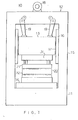
- a press 20 has a movable slide 13 and a bolster 14 fixed on a base 11 of a frame 12.
- An upper mould 21 of a mould assembly 20 is mounted on slide 13, and a lower mould 22 is mounted on bolster 14.
- Guides 16 are fixed to the side 15 of frame 12 and guide the slide 13 for reciprocation.
- Slide 13 is driven by a drive motor 18 via cranks 19.
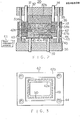
- the mask mould assembly 20 is shown.
- the assembly has an upper manifold 31 which is moved up and down by the slide 13.
- a punch 32 is fitted to the underside of the manifold 31.
- Parts denoted by the numeral 34 are upper pistons which are provided between upper manifold 31 and clamp 33 and serve to move clamp 33 up and down.
- Guide pins 35 are fitted in a vertical direction from upper manifold 31 and mate with guide bushes 36 attached to clamp 33 to guide clamp 33 in its upward and downward motion.
- a lower manifold 38 has a knockout 40 which faces the punch 32, and moves up and down by means of lower pistons 39.
- a die 42 surrounds the outer surface of knockout 40 and can move up and down along the knockout 40.
- the inside corner of the lower edge 52 of the die 42 engages with a protrusion 53 on lower edge of the outer face of knockout 40.
- the protrusion 53 on the lower edge of knockout 40 acts as a stop for the downward movement of die 42.
- Tbe lower mould includes lower manifold 38, knockout 40 and die 42.
- Guide pins 43 are fitted with spacers 45 mounted on top of lower manifold 38 and the pins mate with guide bushes 44 attached to die 42. The guide pins 43 guide the die 42 as it moves up and down. Spacers 45 are mounted on top of lower manifold 38 and confine the downward movement of the die to specified limits.
- Thin plate 47 the material to be formed, typically consists of Fe-Ni alloy, i.e. the thickness of the member 47 is about 0.2 mm or less, e.g. 0.12 mm. After an aperture forming process, it is formed into the shadow mask by a pressing operation on the mould assembly.
- Punch 32 is separately formed as a first punch section 32a which contacts the thin plate 47 and a backing member 32b which does not contact the plate 47.
- Clamp 33 is formed into a first clamp section 33a which contacts the thin plate 47 and a backing member 33b which does not directly contact the thin plate 47.
- Knockout 40 is also formed as a first knockout section 40a which contacts the thin plate 47 and a backing member 40b which does not directly contact the thin plate 47.
- die 42 is formed as a first die section 42a which contacts the thin plate 47 and a backing member 42b which does not directly contact the thin plate 47.
- the. press mould is divided into a first or inner section in contact with the thin plate and a second or outer section in non-contact with the thin plate.
- the first section of the mould i.e. the respective first sections 32a, 33a, 40a and 42a of the mould parts, is supported by the second section, i.e. the respective second sections 32b, 33b, 40b and 42b of the mould parts.
- heating means 50 such as an electric heater, is provided to supply heat for the warm press forming to those first sections which are in direct contact with the thin'plate 47, that is, sections 32a, 33a, 40a and 42a.
- the first sections 32a, 33a, 40a and 42a are preferably of the smallest possible size compatible with the size of the area which contacts the thin plate and the space necessary for a built-in electric heater.
- the first clamp section 33a and the first die section 42a may be split into two or more sections for greater ease of processing.
- the heat insulation 49 should be selected from materials which can withstand the required temperatures and will not greatly deform with the pressure of the press mould, e.g. press-formed glass wool.
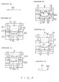
- a thin plate 47 with a large number of apertures is first prepared (process A).
- the thin plate is inserted at the pressed position of the mould 21, 22, the upper manifold 31 is brought down and the non-aperture periphery edge of the thin plate 47 is held fast between the clamp 33 and the die 42 (process B).
- the main section of the thin plate with its plurality of apertures is then pressed between the first punch section 32a and the first knockout section 40a and is formed into a predetermined"curved shape (process C).
- the first sections 32a, 33a, 40a and 42a of the punch 32, the clamp 33, the knockout 40 and the die 42 are heated to the required temperature by their respective electric heaters 50, which are supplied with heating current from a heat current source 51 and then the thin plate 47 is warm press formed.
- the transfer of heat to other sections is reduced by the heat insulating member 49 placed at the divisions.
- the temperature of the second die section 42b of the die 42 can be held to 20 0 C - 30°C.
- seizing in the movement betwen the guide pins 43 in the guide bushes 44 is prevented, and die 42 can be made to move correctly.
- clamp 33 is true for clamp 33.
- the pitch between the guide bushes is easily altered compared with that between the guide pins in order that the guide bushes may be fixed to the temperature rise of the clamp.
- the difference between these pitches causes the seizure described previously.
- the diameter difference i.e. the clearance of the guide bush and the guide pin
- the embodiment of the invention described above satisfies this clearance without seizure.
- the clearance was 0.017 mm.
- the difference of temperature distribution in the mould is also less, thus maintaining high precision of the mask formation.
- the area heated under the warm press forming is from 1/5 - 1/10 of that in the prior art, the capacity of the electric heaters can be much smaller, with a consequent saving in energy. This also means that, with a sufficient margin in the capacity of the heaters, the time taken to heat up to the required temperature can be shortened and production efficiency thus can be improved. Experiments by the inventors showed that the time required for heating can be reduced by as much as 40 minutes to one hour, as compared with the conventional warm press forming device which took two hours.
- en electric heater was used as the heating device, but it is also possible to circulate oil or other fluids in the sections to be heated.
- Press formed glass wool was indicated as suitable for the heat insulating member 49, but it would also be possible to use other materials capable of withstanding the pressure of the press mould, such as compressed mica, asbestos, rock wool or carbonised cork.
Landscapes
- Engineering & Computer Science (AREA)
- Mechanical Engineering (AREA)
- Manufacturing & Machinery (AREA)
- Shaping Metal By Deep-Drawing, Or The Like (AREA)
- Mounting, Exchange, And Manufacturing Of Dies (AREA)
- Moulds For Moulding Plastics Or The Like (AREA)
Applications Claiming Priority (2)
| Application Number | Priority Date | Filing Date | Title |
|---|---|---|---|
| JP114199/86 | 1986-05-19 | ||
| JP61114199A JP2549625B2 (ja) | 1986-05-19 | 1986-05-19 | カラ−受像管用シヤドウマスクの温間成形装置 |
Publications (3)
| Publication Number | Publication Date |
|---|---|
| EP0246838A2 true EP0246838A2 (de) | 1987-11-25 |
| EP0246838A3 EP0246838A3 (en) | 1990-03-07 |
| EP0246838B1 EP0246838B1 (de) | 1993-09-01 |
Family
ID=14631684
Family Applications (1)
| Application Number | Title | Priority Date | Filing Date |
|---|---|---|---|
| EP87304379A Expired - Lifetime EP0246838B1 (de) | 1986-05-19 | 1987-05-18 | Presswerkzeug-Aufbau zur Verwendung bei der Herstellung einer Schattenmaske für eine Farbkathodenstrahlröhre |
Country Status (6)
| Country | Link |
|---|---|
| US (1) | US4792318A (de) |
| EP (1) | EP0246838B1 (de) |
| JP (1) | JP2549625B2 (de) |
| KR (1) | KR900004337B1 (de) |
| CN (1) | CN1005598B (de) |
| DE (1) | DE3787205T2 (de) |
Cited By (5)
| Publication number | Priority date | Publication date | Assignee | Title |
|---|---|---|---|---|
| US5263887A (en) * | 1990-03-30 | 1993-11-23 | Videocolor S.P.A. | Method of forming a color picture tube shadow mask |
| US5306190A (en) * | 1991-10-23 | 1994-04-26 | Videocolor Spa | Forming process for a sheet of perforated metal and process implementation device |
| US20130298629A1 (en) * | 2007-05-22 | 2013-11-14 | Temper Ip, Llc | Method and process for forming a product |
| EP3639939A1 (de) * | 2018-10-18 | 2020-04-22 | The Boeing Company | Warmformpresse und verfahren zum warmformen von werkstücken |
| US11072011B2 (en) | 2018-10-18 | 2021-07-27 | The Boeing Company | Hot boxes for hot-forming presses |
Families Citing this family (8)
| Publication number | Priority date | Publication date | Assignee | Title |
|---|---|---|---|---|
| US6550302B1 (en) * | 1999-07-27 | 2003-04-22 | The Regents Of The University Of Michigan | Sheet metal stamping die design for warm forming |
| US6510601B1 (en) * | 2000-03-20 | 2003-01-28 | The Boeing Company | Invar forming method for making tooling |
| DE102010033816A1 (de) | 2010-06-16 | 2011-12-22 | Giw Gesellschaft Für Innovative Werkzeugsysteme Mbh | Temperiertes Werkzeug |
| TWI510441B (zh) * | 2012-08-29 | 2015-12-01 | G Tech Optoelectronics Corp | 成型模具、使用該玻璃成型模具的玻璃成型裝置及方法 |
| CN105437312B (zh) * | 2014-08-29 | 2018-04-13 | 浙江伟星实业发展股份有限公司 | 采用仿贝扣加工装置加工的仿贝扣加工方法 |
| DE102014118416B4 (de) | 2014-12-11 | 2017-02-23 | Thyssenkrupp Ag | Werkzeug zum Umformen und/oder partiellen Presshärten eines Werkstücks |
| EP3778056B1 (de) * | 2019-08-14 | 2023-07-12 | Umformtechnik Stade GmbH | Verfahren zur warmumformung von aluminiumblechen mittels reckziehens |
| CN111015809B (zh) * | 2019-11-25 | 2021-03-23 | 安徽锐光电子科技有限公司 | 一种带有防过载组件的云母片压型装置及其压型方法 |
Family Cites Families (12)
| Publication number | Priority date | Publication date | Assignee | Title |
|---|---|---|---|---|
| US3096545A (en) * | 1960-07-20 | 1963-07-09 | Rowland Products Inc | Resilient spacer for press-finishing of plastic sheet |
| IT960892B (it) * | 1971-03-27 | 1973-11-30 | Sinram & Wendt | Pressa stira calzoni riscaldabile |
| US3754499A (en) * | 1971-09-27 | 1973-08-28 | North American Rockwell | High temperature platens |
| US4193341A (en) * | 1977-11-03 | 1980-03-18 | Modern Precision Engineers & Associates Limited | Presses |
| US4441945A (en) * | 1979-01-12 | 1984-04-10 | Hoechst Aktiengesellschaft | Method for selective lamination of thermoplastic layers |
| JPS5714423A (en) * | 1980-06-27 | 1982-01-25 | Onkyo Corp | Drawing method for vibration diaphragm |
| JPS5749038U (de) * | 1980-09-05 | 1982-03-19 | ||
| JPS59191600A (ja) * | 1983-04-15 | 1984-10-30 | Hitachi Ltd | ホツトプレス |
| DE3405505C1 (de) * | 1984-02-16 | 1985-01-31 | Herbert Kannegiesser Gmbh + Co, 4973 Vlotho | Vorrichtung zum Verkleben flaechenfoermiger Textilstuecke |
| DE3408619A1 (de) * | 1984-03-09 | 1985-09-12 | Paul Ott Gmbh & Co Kg, 7050 Waiblingen | Elektroheizplatte fuer pressen |
| JPS60220437A (ja) * | 1984-04-16 | 1985-11-05 | Kubota Ltd | プログラムチエツク装置 |
| EP0179506B1 (de) * | 1984-09-28 | 1989-08-02 | Koninklijke Philips Electronics N.V. | Verfahren und Vorrichtung zum Tiefziehen und Biegen einer Schattenmaske für Farbfernsehbildröhre |
-
1986
- 1986-05-19 JP JP61114199A patent/JP2549625B2/ja not_active Expired - Lifetime
-
1987
- 1987-05-15 US US07/049,968 patent/US4792318A/en not_active Expired - Lifetime
- 1987-05-18 EP EP87304379A patent/EP0246838B1/de not_active Expired - Lifetime
- 1987-05-18 DE DE87304379T patent/DE3787205T2/de not_active Expired - Lifetime
- 1987-05-19 CN CN87103713.0A patent/CN1005598B/zh not_active Expired
- 1987-05-19 KR KR1019870004959A patent/KR900004337B1/ko not_active Expired
Cited By (7)
| Publication number | Priority date | Publication date | Assignee | Title |
|---|---|---|---|---|
| US5263887A (en) * | 1990-03-30 | 1993-11-23 | Videocolor S.P.A. | Method of forming a color picture tube shadow mask |
| US5306190A (en) * | 1991-10-23 | 1994-04-26 | Videocolor Spa | Forming process for a sheet of perforated metal and process implementation device |
| US20130298629A1 (en) * | 2007-05-22 | 2013-11-14 | Temper Ip, Llc | Method and process for forming a product |
| US9032772B2 (en) * | 2007-05-22 | 2015-05-19 | Temper Ip, Llc | Method and process for forming a product |
| EP3639939A1 (de) * | 2018-10-18 | 2020-04-22 | The Boeing Company | Warmformpresse und verfahren zum warmformen von werkstücken |
| US11072011B2 (en) | 2018-10-18 | 2021-07-27 | The Boeing Company | Hot boxes for hot-forming presses |
| US11253898B2 (en) | 2018-10-18 | 2022-02-22 | The Boeing Company | Hot-forming presses and methods of hot-forming workpieces |
Also Published As
| Publication number | Publication date |
|---|---|
| KR870011670A (ko) | 1987-12-26 |
| EP0246838A3 (en) | 1990-03-07 |
| DE3787205D1 (de) | 1993-10-07 |
| DE3787205T2 (de) | 1994-02-03 |
| CN1005598B (zh) | 1989-10-25 |
| JP2549625B2 (ja) | 1996-10-30 |
| CN87103713A (zh) | 1987-11-25 |
| JPS62270225A (ja) | 1987-11-24 |
| EP0246838B1 (de) | 1993-09-01 |
| KR900004337B1 (ko) | 1990-06-22 |
| US4792318A (en) | 1988-12-20 |
Similar Documents
| Publication | Publication Date | Title |
|---|---|---|
| EP0246838A2 (de) | Presswerkzeug-Aufbau zur Verwendung bei der Herstellung einer Schattenmaske für eine Farbkathodenstrahlröhre | |
| KR100229686B1 (ko) | 판유리의 가압굽힘성형방법 및 장치 | |
| RU95108246A (ru) | Способ и устройство выпуклого изгибания стеклянной пластины | |
| US20230202902A1 (en) | Device and method for bending vehicle glass | |
| KR101764795B1 (ko) | 윈도우 글라스 곡면 자동 성형 장치 | |
| CN112358170A (zh) | 一种3d玻璃成型装置及其3d玻璃的制备方法 | |
| JP2000062023A (ja) | エンボスキャリアテープ成型機 | |
| CN110216196A (zh) | 钢补丁板的浮动凸模热成形模具和热冲压成形方法 | |
| CN114149170A (zh) | 一种曲面玻璃热压加工工艺 | |
| CN210059556U (zh) | 钢补丁板的浮动凸模热成形模具 | |
| CN108545916A (zh) | 一种玻璃板热弯成型机 | |
| CN117964221A (zh) | 异形玻璃热成型装置及成型方法 | |
| CN113336426A (zh) | 一种玻璃盖板的热成型模具及热成型方法 | |
| CN213082322U (zh) | 一种吸塑托盘的分段冲压成型模架及模具 | |
| CN222817763U (zh) | 模具 | |
| KR102147345B1 (ko) | 유리기판의 엣지용 성형장치 | |
| CN218969093U (zh) | 一种3d玻璃成型模具 | |
| CN208440512U (zh) | 一种玻璃板热弯成型石墨模具 | |
| JPH06305744A (ja) | 光学素子製造装置 | |
| JPH0455763B2 (de) | ||
| CN222119075U (zh) | 一种带有弧度调节结构的玻璃加工热弯装置 | |
| CN218660427U (zh) | 一种具有均匀加热片材的吸塑成型机 | |
| KR102365297B1 (ko) | 다축대각단조 장치 | |
| JP2509305B2 (ja) | ガラスレンズの成形方法と装置 | |
| KR102185912B1 (ko) | 자동차용 마그네슘 부품의 제조방법 |
Legal Events
| Date | Code | Title | Description |
|---|---|---|---|
| PUAI | Public reference made under article 153(3) epc to a published international application that has entered the european phase |
Free format text: ORIGINAL CODE: 0009012 |
|
| 17P | Request for examination filed |
Effective date: 19870522 |
|
| AK | Designated contracting states |
Kind code of ref document: A2 Designated state(s): DE FR GB |
|
| PUAL | Search report despatched |
Free format text: ORIGINAL CODE: 0009013 |
|
| AK | Designated contracting states |
Kind code of ref document: A3 Designated state(s): DE FR GB |
|
| 17Q | First examination report despatched |
Effective date: 19920403 |
|
| GRAA | (expected) grant |
Free format text: ORIGINAL CODE: 0009210 |
|
| AK | Designated contracting states |
Kind code of ref document: B1 Designated state(s): DE FR GB |
|
| ET | Fr: translation filed | ||
| REF | Corresponds to: |
Ref document number: 3787205 Country of ref document: DE Date of ref document: 19931007 |
|
| PLBE | No opposition filed within time limit |
Free format text: ORIGINAL CODE: 0009261 |
|
| STAA | Information on the status of an ep patent application or granted ep patent |
Free format text: STATUS: NO OPPOSITION FILED WITHIN TIME LIMIT |
|
| 26N | No opposition filed | ||
| REG | Reference to a national code |
Ref country code: GB Ref legal event code: 746 Effective date: 19981012 |
|
| REG | Reference to a national code |
Ref country code: FR Ref legal event code: D6 |
|
| REG | Reference to a national code |
Ref country code: GB Ref legal event code: IF02 |
|
| PGFP | Annual fee paid to national office [announced via postgrant information from national office to epo] |
Ref country code: DE Payment date: 20060511 Year of fee payment: 20 |
|
| PGFP | Annual fee paid to national office [announced via postgrant information from national office to epo] |
Ref country code: FR Payment date: 20060515 Year of fee payment: 20 |
|
| PGFP | Annual fee paid to national office [announced via postgrant information from national office to epo] |
Ref country code: GB Payment date: 20060517 Year of fee payment: 20 |
|
| REG | Reference to a national code |
Ref country code: GB Ref legal event code: PE20 |
|
| PG25 | Lapsed in a contracting state [announced via postgrant information from national office to epo] |
Ref country code: GB Free format text: LAPSE BECAUSE OF EXPIRATION OF PROTECTION Effective date: 20070517 |