EP0246782A2 - Verfahren und Anlage für selbstansaugende Flüssigkeitsringpumpe - Google Patents
Verfahren und Anlage für selbstansaugende Flüssigkeitsringpumpe Download PDFInfo
- Publication number
- EP0246782A2 EP0246782A2 EP87304068A EP87304068A EP0246782A2 EP 0246782 A2 EP0246782 A2 EP 0246782A2 EP 87304068 A EP87304068 A EP 87304068A EP 87304068 A EP87304068 A EP 87304068A EP 0246782 A2 EP0246782 A2 EP 0246782A2
- Authority
- EP
- European Patent Office
- Prior art keywords
- gas
- bypass conduit
- pump
- outlet
- inlet
- Prior art date
- Legal status (The legal status is an assumption and is not a legal conclusion. Google has not performed a legal analysis and makes no representation as to the accuracy of the status listed.)
- Granted
Links
Images


Classifications
-
- F—MECHANICAL ENGINEERING; LIGHTING; HEATING; WEAPONS; BLASTING
- F04—POSITIVE - DISPLACEMENT MACHINES FOR LIQUIDS; PUMPS FOR LIQUIDS OR ELASTIC FLUIDS
- F04C—ROTARY-PISTON, OR OSCILLATING-PISTON, POSITIVE-DISPLACEMENT MACHINES FOR LIQUIDS; ROTARY-PISTON, OR OSCILLATING-PISTON, POSITIVE-DISPLACEMENT PUMPS
- F04C19/00—Rotary-piston pumps with fluid ring or the like, specially adapted for elastic fluids
- F04C19/004—Details concerning the operating liquid, e.g. nature, separation, cooling, cleaning, control of the supply
Definitions
- This invention relates to liquid ring gas pumps.
- Liquid ring gas pumps generally require a substantially continuous inflow of fresh or recirculated pumping liquid (sometimes referred to as "make-up" pumping liquid) to replace the pumping liquid that is normally lost via the gas discharge port.
- This flow of pumping liquid through the pump is also used to absorb some of the heat generated in the pump, thereby preventing the pump from overheating.
- a substantially continuous inflow of make-up pumping liquid is therefore essential to successful operation of a liquid ring pump.
- liquid ring pumps that are self-priming, i.e., liquid ring pumps that can themselves initiate and sustain a recirculating flow of pumping liquid partly external to the pump (and create a properly formed internal liquid ring utilizing this liquid) without the need for a separate liquid pump.
- liquid ring pumps having a bypass conduit, the inlet (but not the outlet) of which is immersed in pumping liquid when the pump is at a standstill ready to be started.
- the pump is first started, typically before the liquid ring has properly formed and created sufficient suction to pull recirculated pumping liquid into the pump, the relatively high pressure of the pumping liquid adjacent the bypass conduit inlet causes pumping liquid to flow through the bypass conduit from its inlet to its outlet.
- This "bypass pumping liquid” is believed to promote successful pump operation in two ways. First, it helps seal the pump between its intake and discharge ports even though the liquid ring may be somewhat depleted due to the temporary initial absence of pumping liquid inflow. Second, a portion of this bypass pumping liquid is added to the nascent liquid ring in the compression zone, thus enhancing formation of a stable liquid ring.
- the enhanced sealing and liquid ring formation apparently provided by the bypass pumping liquid is believed to help the pump to pump sufficient gas to begin to establish a gas pressure differential between the intake and discharge ports of the pump. Once such a gas pressure differential has been established, the relatively low pressure in the pump begins to pull recirculated pumping liquid into the pump, thereby establishing and subsequently maintaining the inflow of recirculated pumping liquid necessary for continued full operation of the pump. In addition, all or a major portion of any carry-over gas reaching the bypass conduit inlet flows through the bypass conduit, thereby bypassing the intake zone of the pump and improving the volumetric efficiency of the pump.
- the bypass conduit comprises a clearance between the rotor shaft and the port member, a first aperture through the port member from the bypass conduit inlet on the outer surface of the port member to the clearance, and a second aperture through the port member from the clearance to the bypass conduit outlet on the outer surface of the port member.
- the recirculated pumping liquid inlet is also connected to the clearance.
- the bypass conduit comprises a circumferential or partly circumferential passageway in the port member, a first aperture through the port member from the bypass conduit inlet on the inner (rotor side) surface of the port member to the passageway, and a second aperture through the port member from the passageway to the bypass conduit outlet also on the inner surface of the port member.
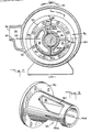
- a conically ported liquid ring pump l0 constructed in accordance with the principles of this invention includes rotor 40 rotatably mounted in stationary annular housing 60.
- Rotor 40 is fixedly mounted on shaft 42 which is rotatably mounted in bearing assemblies 44 adjacent each end of housing 60 (only one end of which is shown in FIG. l).
- Gas to be pumped enters the pump via inlet opening l2 in head number l4. Inside head member l4, the gas flows via conduit l6 into conduit 22 in stationary conical port member 20.
- Port member 20 extends into an annular clearance between shaft 42 and one end portion of rotor 40.
- Gas from conduit 22 flows into the spaces between rotor blades 46 via intake port 24 in what is called the intake zone 26 of the pump (see FIG. 2).
- rotor 40 (rotating in the direction indicated by arrow 70) conveys the gas from intake zone 26 to compression zone 28, simultaneously compressing the gas thus conveyed.
- the compressed gas exits from compression zone 28 via discharge port 30, port member conduit 32, and head member and housing conduit 34, ultimately exiting from the pump via outlet opening 36.
- the structure shown in FIG. l may comprise substantially the entire liquid ring pump (with only the addition of a cover structure and bearing assembly to the left of match line A-A in FIG. 1).
- the structure shown in FIG. l may be duplicated in mirror image to the left of match line A-A to produce a double-ended pump.
- a similar but smaller second-stage pump structure may be provided to the left of match line A-A to produce a two-stage pump with outlet opening 36 being connected to the inlet opening of the second stage.
- any compressed gas that is not discharged from rotor 40 via discharge port 30 bypasses intake zone 26 by flowing through bypass conduit 50 (comprising inlet 50a, initial portion 50b, clearance 50c, final portion 50d, and outlet 50e).
- Inlet 50a is an aperture in the outer surface of port member 20 which is radially opposite the "land" region of the pump (i.e., the point at which the tips of rotor blades 46 are closest to the inner surface of housing 60). From inlet 50a, the initial portion 50b of conduit 50 extends radially through port member 20 to an annular clearance 50c between the annular inner surface of port member 20 and the annular outer surface of shaft 42.
- conduit 50 again extends radially through port member 20 to outlet aperture 50e on the outer surface of port member 20.
- Outlet aperture 50e is located after intake port 24 but before discharge port 30 in the direction of rotor rotation.
- the cooled pumping liquid is recirculated from heat exchanger 90 to pump l0 via conduit 96 (see also FIG. l). Any required make-up pumping liquid is supplied to the system via conduit 76, the flow from which is typically controlled by a float valve (not shown) in separator 80.
- conduit 96 preferably communicates with clearance 50c via conduit l8 in head member l4 and conduit 38 in port member 20.
- the angular location of elements 96, l8, and 38 is not critical and can be selected to suit the convenience of the designer.
- bypass conduit inlet 50a which communicates with the land region of the pump, is below the level 64 of the pumping liquid with which pump l0 is typically started.
- pump l0 is typically filled with pumping liquid to the threshold 62 of outlet 36 in preparation for starting the pump.
- This starting pumping liquid level 64 preferively corresponds to the starting and steady-state operating pumping liquid level in separator 80.
- starting pumping liquid level 64 is preferably at or slightly above the centerline of shaft 42. This places bypass conduit inlet 50a well below starting pumping liquid level 64.
- Bypass conduit outlet 50e is preferably above the surface 64 of the starting pumping liquid.
- pump l0 When pump l0 is started, it initially tends to discharge a portion of the starting pumping liquid via outlet 36. Because there is no liquid pump to force make-up pumping liquid into pump l0 via conduit 96, the liquid ring forming in the pump tends to be depleted until sufficiently low gas pressure is established adjacent bypass conduit outlet 50e to begin to pull pumping liquid into the pump via conduits 96, l8, 38, 50c, and 50d. On the other hand, because the liquid ring is depleted, the pump is generally unable (in the absence of the present invention) to properly distribute the remaining pumping liquid as a viable liquid ring capable of pumping sufficient gas to establish the pressure differential needed to initiate the inflow of recirculated pumping liquid.
- bypass conduit inlet 50a below the starting pumping liquid level, the above-described stall condition during start-up can be avoided without resorting to the addition of a liquid pump to initiate recirculated pumping liquid inflow into the pump.
- bypass conduit inlet 50a is exposed to a sufficiently high pumping liquid pressure (by virtue of being flooded and also located adjacent the land region of the pump) to cause some pumping liquid from the lower portion of the liquid ring adjacent inlet 50a to flow through conduit 50 and re-enter the liquid ring near the top of the pump adjacent to outlet 50e.
- This flow of pumping liquid is believed to help prevent gas leakage and to optimize distribution of liquid within the pump during the relatively brief start-up interval in which the liquid ring is depleted.
- conduit 50 performs several related functions. During pump start-up, conduit 50 is believed to convey pumping liquid from its inlet 50a to its outlet 50e to render the pump self-priming. The portions 50c, 50d, and 50e of conduit 50 also convey the recirculated pumping liquid from conduit 96 into the pump. Conduit 50 also acts as a bypass conduit to improve the volumetric efficiency of the pump.
- FIG. 5 shows the preferred locations and relative sizes of bypass conduit inlet 50a and outlet 50e.
- Initial conduit portion 50b is the same size as inlet 50a
- final conduit portion 50d is the same size as outlet 50e.
- inlet 50a is adjacent the land region of the pump, and is also below the start-up pumping liquid level of the pump.
- inlet 50a is preferably disposed in the portion of port member 20 adjacent to which carry-over gas is most likely to occur. In a conically ported pump such as pump l0, this is the smaller diameter portion of port member 20.
- Angularly, inlet 50a is approximately midway between the completion of the compression cycle and initiation of the intake zone.
- Outlet 50e is located beyond intake port 24 but before discharge port 30 in the direction of rotor rotation. Outlet 50e is also preferably substantially larger than inlet 50a to promote fluid flow from the inlet to the outlet, and to allow con duit portion 50d to accommodate both the fluid from conduit portion 50b and the recirculated pumping liquid from conduit 96. Outlet 50e is preferably axially long enough to distribute the liquid exiting from it along substantially the entire length of port member 20. This is believed to enhance the sealing effect of the pumping liquid discharged from outlet 50e during the self-priming start-up interval.
- FIGS. 7-10 show application of the principles of this invention to a side ported liquid ring pump.
- the pump of FIGS. 7-l0 is different from the pump of FIGS. 1-5, the same reference numbers are used for generally analogous parts in both pumps.
- the pump of FIGS. 7-10 can be used as pump 10 in the system of FIG. 6.
- FIGS. 7-10 The major difference between the pump of FIGS. 7-10 and the pump of FIGS. 1-5 is that in FIGS. 7-10 port member 20 is substantially flat and does not project into any annular clearance between rotor 40 and shaft 42.
- the inlet 50a to bypass conduit 50 is formed as a first radial aperture adjacent the land region of the pump.
- the outlet of bypass conduit 50 is formed as a second radial aperture 50e after the intake port 24 but before discharge port 30 in the direction of rotor rotation.
- Inlet 50a and outlet 50e are interconnected by an enclosed passageway 50c which is formed for the most part on the surface of port member 20 facing away from rotor 40. Passageway 50c is at least partly circumferential of the pump in order to convey bypass fluid around shaft 42 from inlet 50a to outlet 50e.
- Recirculated pumping liquid enters the pump of FIGS. 7-10 via conduit 96 and fills conduit 18 in head member 14. This liquid enters the pumping chamber of the pump (i.e., housing 60) via conduit 38 and an annular clearance 52 between port member 20, on the one hand, and shaft 42 and the axial end of rotor hub 48, on the other hand.
Landscapes
- Engineering & Computer Science (AREA)
- Mechanical Engineering (AREA)
- General Engineering & Computer Science (AREA)
- Structures Of Non-Positive Displacement Pumps (AREA)
- Control Of Non-Positive-Displacement Pumps (AREA)
Applications Claiming Priority (2)
| Application Number | Priority Date | Filing Date | Title |
|---|---|---|---|
| US864269 | 1986-05-19 | ||
| US06/864,269 US4679987A (en) | 1986-05-19 | 1986-05-19 | Self-priming liquid ring pump methods and apparatus |
Publications (3)
| Publication Number | Publication Date |
|---|---|
| EP0246782A2 true EP0246782A2 (de) | 1987-11-25 |
| EP0246782A3 EP0246782A3 (en) | 1988-09-28 |
| EP0246782B1 EP0246782B1 (de) | 1991-09-04 |
Family
ID=25342884
Family Applications (1)
| Application Number | Title | Priority Date | Filing Date |
|---|---|---|---|
| EP87304068A Expired - Lifetime EP0246782B1 (de) | 1986-05-19 | 1987-05-07 | Verfahren und Anlage für selbstansaugende Flüssigkeitsringpumpe |
Country Status (10)
| Country | Link |
|---|---|
| US (1) | US4679987A (de) |
| EP (1) | EP0246782B1 (de) |
| JP (1) | JP2553551B2 (de) |
| KR (1) | KR960004250B1 (de) |
| AU (1) | AU588194B2 (de) |
| BR (1) | BR8702523A (de) |
| CA (1) | CA1291464C (de) |
| DE (1) | DE3772623D1 (de) |
| FI (1) | FI93258C (de) |
| ZA (1) | ZA872895B (de) |
Cited By (5)
| Publication number | Priority date | Publication date | Assignee | Title |
|---|---|---|---|---|
| EP0274272A3 (en) * | 1987-01-08 | 1989-02-01 | The Nash Engineering Company | Two stage liquid ring pump |
| EP0374798A3 (de) * | 1988-12-21 | 1991-07-03 | Leif Blumenau | Flüssigabgedichteter Flügelzellenoszillator |
| EP0599545A1 (de) * | 1992-11-20 | 1994-06-01 | Gad Assaf | Verdichter/Turbine mit einem Flüssigkeitsring für ein Klimatisierungssystem |
| US5636523A (en) * | 1992-11-20 | 1997-06-10 | Energy Converters Ltd. | Liquid ring compressor/turbine and air conditioning systems utilizing same |
| GB2405906A (en) * | 2003-09-12 | 2005-03-16 | Aesseal Plc | Liquid ring vacuum pump with automatically maintained level of barrier fluid |
Families Citing this family (14)
| Publication number | Priority date | Publication date | Assignee | Title |
|---|---|---|---|---|
| US5186219A (en) * | 1984-11-08 | 1993-02-16 | Earth Resources Consultants, Inc. | Cylinder rupture vessel |
| US5383499A (en) * | 1992-05-04 | 1995-01-24 | Earth Resources Corporation | System for removal of unknown, corrossive, or potentially hazardous gases from a gas container |
| US5474114A (en) | 1993-05-28 | 1995-12-12 | Earth Resources Corporation | Apparatus and method for controlled penetration of compressed fluid cylinders |
| US5525070A (en) * | 1994-04-15 | 1996-06-11 | Panduit Corp. | Positive lock insulated disconnect |
| CN1079503C (zh) * | 1995-08-16 | 2002-02-20 | 西门子公司 | 液体环式压缩机 |
| US5900216A (en) * | 1996-06-19 | 1999-05-04 | Earth Resources Corporation | Venturi reactor and scrubber with suckback prevention |
| US5868174A (en) * | 1997-07-28 | 1999-02-09 | Earth Resources Corporation | System for accessing and extracting contents from a container within a sealable recovery vessel |
| US6164344A (en) * | 1997-07-28 | 2000-12-26 | Earth Resources Corporation | Sealable recovery vessel system and method for accessing valved containers |
| DE19847681C1 (de) * | 1998-10-15 | 2000-06-15 | Siemens Ag | Flüssigkeitsringpumpe |
| CN102257277B (zh) | 2008-12-18 | 2015-03-11 | 佶缔纳士机械有限公司 | 具有换气装置的液环泵 |
| CN105545740B (zh) * | 2009-06-26 | 2018-03-16 | 佶缔纳士机械有限公司 | 转换具有密封液体排放的液体环式泵的方法 |
| US9689387B2 (en) | 2012-10-30 | 2017-06-27 | Gardner Denver Nash, Llc | Port plate of a flat sided liquid ring pump having a gas scavenge passage therein |
| KR20170108031A (ko) * | 2015-01-08 | 2017-09-26 | 가드너 덴버 내쉬 엘엘씨 | 압축기 유형 액체 링 펌프의 저압 밀봉 액체 입구 영역 |
| KR101926960B1 (ko) * | 2017-02-10 | 2018-12-07 | 주식회사 케이씨씨 | 저반사 코팅 유리 |
Family Cites Families (17)
| Publication number | Priority date | Publication date | Assignee | Title |
|---|---|---|---|---|
| DE258483C (de) * | ||||
| DE258854C (de) * | ||||
| US1322363A (en) * | 1917-08-07 | 1919-11-18 | Siemens Schuckertwerke Gmbh | Rotary blower or pump. |
| US2195174A (en) * | 1935-12-30 | 1940-03-26 | Irving C Jennings | Pump |
| US2195375A (en) * | 1935-12-30 | 1940-03-26 | Nash Engineering Co | Pump |
| GB809294A (en) * | 1955-02-08 | 1959-02-18 | Siemens Ag | Improvements in or relating to liquid-ring pumps |
| US3032258A (en) * | 1958-09-04 | 1962-05-01 | Nash Engineering Co | Vacuum pumps |
| US3043498A (en) * | 1959-12-29 | 1962-07-10 | Gabbioneta Roberto | Rotary liquid ring pump with means for regulating the loading of liquid in the ring |
| FR1276528A (fr) * | 1960-12-22 | 1961-11-17 | Dispositif de support du rotor dans les pompes rotatives à anneau liquide | |
| GB1284473A (en) * | 1969-04-26 | 1972-08-09 | Siemens Ag | Improvements in or relating to liquid ring pumps |
| FR2264201B1 (de) * | 1974-03-13 | 1979-08-17 | Siemens Ag | |
| DE2541050B2 (de) * | 1975-09-15 | 1977-09-29 | Siemens AG, 1000 Berlin und 8000 München | Fluessigkeitsringverdichter |
| US4083658A (en) * | 1976-09-08 | 1978-04-11 | Siemens Aktiengesellschaft | Liquid ring compressor including a calibrated gas input opening |
| SU914809A1 (ru) * | 1980-06-26 | 1982-03-23 | Lev T Karaganov | Жидкостнокольцевая машина 1 |
| DE3124867C2 (de) * | 1981-06-24 | 1983-11-17 | Siemens AG, 1000 Berlin und 8000 München | Flüssigkeitsring-Vakuumpumpe für gasförmige Medien |
| US4521161A (en) * | 1983-12-23 | 1985-06-04 | The Nash Engineering Company | Noise control for conically ported liquid ring pumps |
| US4613283A (en) * | 1985-06-26 | 1986-09-23 | The Nash Engineering Company | Liquid ring compressors |
-
1986
- 1986-05-19 US US06/864,269 patent/US4679987A/en not_active Expired - Lifetime
-
1987
- 1987-04-23 ZA ZA872895A patent/ZA872895B/xx unknown
- 1987-05-07 EP EP87304068A patent/EP0246782B1/de not_active Expired - Lifetime
- 1987-05-07 DE DE8787304068T patent/DE3772623D1/de not_active Expired - Lifetime
- 1987-05-12 JP JP62113721A patent/JP2553551B2/ja not_active Expired - Lifetime
- 1987-05-13 CA CA000536994A patent/CA1291464C/en not_active Expired - Lifetime
- 1987-05-13 AU AU72770/87A patent/AU588194B2/en not_active Expired
- 1987-05-18 BR BR8702523A patent/BR8702523A/pt not_active IP Right Cessation
- 1987-05-18 FI FI872182A patent/FI93258C/fi not_active IP Right Cessation
- 1987-05-19 KR KR1019870005018A patent/KR960004250B1/ko not_active Expired - Lifetime
Cited By (7)
| Publication number | Priority date | Publication date | Assignee | Title |
|---|---|---|---|---|
| EP0274272A3 (en) * | 1987-01-08 | 1989-02-01 | The Nash Engineering Company | Two stage liquid ring pump |
| EP0374798A3 (de) * | 1988-12-21 | 1991-07-03 | Leif Blumenau | Flüssigabgedichteter Flügelzellenoszillator |
| EP0599545A1 (de) * | 1992-11-20 | 1994-06-01 | Gad Assaf | Verdichter/Turbine mit einem Flüssigkeitsring für ein Klimatisierungssystem |
| US5636523A (en) * | 1992-11-20 | 1997-06-10 | Energy Converters Ltd. | Liquid ring compressor/turbine and air conditioning systems utilizing same |
| GB2405906A (en) * | 2003-09-12 | 2005-03-16 | Aesseal Plc | Liquid ring vacuum pump with automatically maintained level of barrier fluid |
| GB2405906B (en) * | 2003-09-12 | 2006-08-30 | Aesseal Plc | A system and method for regulating the volume of barrier fluid in a liquid ring vacuum pump |
| US7258143B2 (en) | 2003-09-12 | 2007-08-21 | Aes Engineering Ltd. | System and method for regulating the volume of barrier fluid in a liquid ring vacuum pump |
Also Published As
| Publication number | Publication date |
|---|---|
| EP0246782B1 (de) | 1991-09-04 |
| KR870011386A (ko) | 1987-12-23 |
| AU588194B2 (en) | 1989-09-07 |
| BR8702523A (pt) | 1988-02-23 |
| FI93258C (fi) | 1995-03-10 |
| EP0246782A3 (en) | 1988-09-28 |
| DE3772623D1 (de) | 1991-10-10 |
| FI872182A7 (fi) | 1987-11-20 |
| US4679987A (en) | 1987-07-14 |
| AU7277087A (en) | 1987-11-26 |
| FI872182A0 (fi) | 1987-05-18 |
| CA1291464C (en) | 1991-10-29 |
| JPS62271991A (ja) | 1987-11-26 |
| ZA872895B (en) | 1987-11-25 |
| KR960004250B1 (ko) | 1996-03-28 |
| JP2553551B2 (ja) | 1996-11-13 |
| FI93258B (fi) | 1994-11-30 |
Similar Documents
| Publication | Publication Date | Title |
|---|---|---|
| EP0246782A2 (de) | Verfahren und Anlage für selbstansaugende Flüssigkeitsringpumpe | |
| CA2147644C (en) | Scroll apparatus with reduced inlet pressure drop | |
| JP3136174B2 (ja) | 冷媒圧縮機 | |
| US20110314830A1 (en) | Oil supply system with main pump deaeration | |
| CN101451467A (zh) | 气-油分离器 | |
| AU606566B2 (en) | Scroll compressor with orbiting scroll member biased by oil pressure | |
| US12378915B2 (en) | Fuel supply circuit of an aircraft engine | |
| US4714405A (en) | Centrifugal pump | |
| JP4972259B2 (ja) | 遠心ポンプ | |
| US4811471A (en) | Method of assembling scroll compressors | |
| KR910012535A (ko) | 가스제거 기능을 갖는 액체펌프 | |
| JPS60138297A (ja) | 円周流式液体ポンプ | |
| RU2134821C1 (ru) | Бустерный насосный агрегат жрд | |
| EP0856664B1 (de) | Zweistufige Flüssigkeitsringpumpen | |
| JP2000145681A (ja) | 水車駆動ターボポンプ | |
| JPH08200277A (ja) | ガス抜き弁内蔵遠心ポンプ | |
| EP0145738B1 (de) | Centrifugalpumpe | |
| JP2002310086A (ja) | シールレスモータポンプ | |
| JP2560857B2 (ja) | スクロール形流体機械 | |
| JPH10288175A (ja) | 油冷式スクリュ圧縮機 | |
| JPS63314392A (ja) | 燃料タンク内蔵式燃料ポンプ装置 | |
| JP2006329157A (ja) | 油冷式圧縮機 | |
| JPS5925098A (ja) | 油回転真空ポンプの注油装置 | |
| US20030091434A1 (en) | Pump having multiple volute passages and method of pumping fluid | |
| JPH0735084A (ja) | 立軸プルアウト形自吸ポンプ |
Legal Events
| Date | Code | Title | Description |
|---|---|---|---|
| PUAI | Public reference made under article 153(3) epc to a published international application that has entered the european phase |
Free format text: ORIGINAL CODE: 0009012 |
|
| AK | Designated contracting states |
Kind code of ref document: A2 Designated state(s): BE DE GB SE |
|
| PUAL | Search report despatched |
Free format text: ORIGINAL CODE: 0009013 |
|
| AK | Designated contracting states |
Kind code of ref document: A3 Designated state(s): BE DE GB SE |
|
| 17P | Request for examination filed |
Effective date: 19890309 |
|
| 17Q | First examination report despatched |
Effective date: 19891106 |
|
| GRAA | (expected) grant |
Free format text: ORIGINAL CODE: 0009210 |
|
| AK | Designated contracting states |
Kind code of ref document: B1 Designated state(s): BE DE GB SE |
|
| PG25 | Lapsed in a contracting state [announced via postgrant information from national office to epo] |
Ref country code: BE Effective date: 19910904 |
|
| REF | Corresponds to: |
Ref document number: 3772623 Country of ref document: DE Date of ref document: 19911010 |
|
| PLBI | Opposition filed |
Free format text: ORIGINAL CODE: 0009260 |
|
| 26 | Opposition filed |
Opponent name: SIEMENS AG GR PA 2 ERL S Effective date: 19920512 |
|
| PLBN | Opposition rejected |
Free format text: ORIGINAL CODE: 0009273 |
|
| STAA | Information on the status of an ep patent application or granted ep patent |
Free format text: STATUS: OPPOSITION REJECTED |
|
| 27O | Opposition rejected |
Effective date: 19940711 |
|
| EAL | Se: european patent in force in sweden |
Ref document number: 87304068.7 |
|
| REG | Reference to a national code |
Ref country code: GB Ref legal event code: IF02 |
|
| REG | Reference to a national code |
Ref country code: GB Ref legal event code: 732E |
|
| PGFP | Annual fee paid to national office [announced via postgrant information from national office to epo] |
Ref country code: GB Payment date: 20060525 Year of fee payment: 20 |
|
| PGFP | Annual fee paid to national office [announced via postgrant information from national office to epo] |
Ref country code: SE Payment date: 20060530 Year of fee payment: 20 |
|
| PGFP | Annual fee paid to national office [announced via postgrant information from national office to epo] |
Ref country code: DE Payment date: 20060630 Year of fee payment: 20 |
|
| REG | Reference to a national code |
Ref country code: GB Ref legal event code: PE20 |
|
| EUG | Se: european patent has lapsed | ||
| PG25 | Lapsed in a contracting state [announced via postgrant information from national office to epo] |
Ref country code: GB Free format text: LAPSE BECAUSE OF EXPIRATION OF PROTECTION Effective date: 20070506 |