EP0246450A2 - Automobilkühlerdeckel - Google Patents
Automobilkühlerdeckel Download PDFInfo
- Publication number
- EP0246450A2 EP0246450A2 EP87105639A EP87105639A EP0246450A2 EP 0246450 A2 EP0246450 A2 EP 0246450A2 EP 87105639 A EP87105639 A EP 87105639A EP 87105639 A EP87105639 A EP 87105639A EP 0246450 A2 EP0246450 A2 EP 0246450A2
- Authority
- EP
- European Patent Office
- Prior art keywords
- pressure
- pressure valve
- valve
- connecting hole
- tank
- Prior art date
- Legal status (The legal status is an assumption and is not a legal conclusion. Google has not performed a legal analysis and makes no representation as to the accuracy of the status listed.)
- Granted
Links
- 239000000945 filler Substances 0.000 claims abstract description 31
- 238000007789 sealing Methods 0.000 claims abstract description 31
- 239000002826 coolant Substances 0.000 claims description 43
- 239000002184 metal Substances 0.000 claims description 3
- 239000000463 material Substances 0.000 claims description 2
- 239000000956 alloy Substances 0.000 claims 1
- 229910045601 alloy Inorganic materials 0.000 claims 1
- 238000002303 thermal reforming Methods 0.000 claims 1
- 238000009835 boiling Methods 0.000 description 5
- 230000005484 gravity Effects 0.000 description 3
- 230000007423 decrease Effects 0.000 description 2
- XLYOFNOQVPJJNP-UHFFFAOYSA-N water Substances O XLYOFNOQVPJJNP-UHFFFAOYSA-N 0.000 description 2
- 206010025482 malaise Diseases 0.000 description 1
- 229910001285 shape-memory alloy Inorganic materials 0.000 description 1
- 238000003466 welding Methods 0.000 description 1
Images


Classifications
-
- B—PERFORMING OPERATIONS; TRANSPORTING
- B60—VEHICLES IN GENERAL
- B60K—ARRANGEMENT OR MOUNTING OF PROPULSION UNITS OR OF TRANSMISSIONS IN VEHICLES; ARRANGEMENT OR MOUNTING OF PLURAL DIVERSE PRIME-MOVERS IN VEHICLES; AUXILIARY DRIVES FOR VEHICLES; INSTRUMENTATION OR DASHBOARDS FOR VEHICLES; ARRANGEMENTS IN CONNECTION WITH COOLING, AIR INTAKE, GAS EXHAUST OR FUEL SUPPLY OF PROPULSION UNITS IN VEHICLES
- B60K11/00—Arrangement in connection with cooling of propulsion units
-
- F—MECHANICAL ENGINEERING; LIGHTING; HEATING; WEAPONS; BLASTING
- F01—MACHINES OR ENGINES IN GENERAL; ENGINE PLANTS IN GENERAL; STEAM ENGINES
- F01P—COOLING OF MACHINES OR ENGINES IN GENERAL; COOLING OF INTERNAL-COMBUSTION ENGINES
- F01P11/00—Component parts, details, or accessories not provided for in, or of interest apart from, groups F01P1/00 - F01P9/00
- F01P11/02—Liquid-coolant filling, overflow, venting, or draining devices
- F01P11/0204—Filling
- F01P11/0209—Closure caps
- F01P11/0238—Closure caps with overpressure valves or vent valves
-
- F—MECHANICAL ENGINEERING; LIGHTING; HEATING; WEAPONS; BLASTING
- F01—MACHINES OR ENGINES IN GENERAL; ENGINE PLANTS IN GENERAL; STEAM ENGINES
- F01P—COOLING OF MACHINES OR ENGINES IN GENERAL; COOLING OF INTERNAL-COMBUSTION ENGINES
- F01P11/00—Component parts, details, or accessories not provided for in, or of interest apart from, groups F01P1/00 - F01P9/00
-
- Y—GENERAL TAGGING OF NEW TECHNOLOGICAL DEVELOPMENTS; GENERAL TAGGING OF CROSS-SECTIONAL TECHNOLOGIES SPANNING OVER SEVERAL SECTIONS OF THE IPC; TECHNICAL SUBJECTS COVERED BY FORMER USPC CROSS-REFERENCE ART COLLECTIONS [XRACs] AND DIGESTS
- Y10—TECHNICAL SUBJECTS COVERED BY FORMER USPC
- Y10S—TECHNICAL SUBJECTS COVERED BY FORMER USPC CROSS-REFERENCE ART COLLECTIONS [XRACs] AND DIGESTS
- Y10S220/00—Receptacles
- Y10S220/32—Radiator cap
Definitions
- the present invention relates to an automotive radiator cap detouchably connected with a filler neck of an automotive radiator.
- Numeral 501 in Fig. 5 shows a top surface of a filler neck
- numeral 503 shows pressure valve
- letter F 0 shows closing force of the coil spring.
- the divided force F 1 Since the coil spring is contacted with the pressure valve 503 at the portion which is higher than the top surface 501 of the filler neck, and since the closing force F 0 forces a top surface 505 of the pressure valve 503 virtically, the divided force F 1 the orientation of which is parallel with the top surface 505 of the pressure valve 503 is occurred when the pressure valve 503 is inclined as shown in Fig. 5.
- the divided force F l is calculated as next formula wherein means opening angle of the pressure valve 503 and D shows the distance between the top surface 505 of the pressure valve 503 and a sealing portion 507 of the pressure valve 503.
- the divided force F 1 causes a rotating moment M 0 which is calculated as next formula
- the divided force F 1 makes the pressure valve 503 open even though the coil spring biases the pressure valve 503 to the closing position. Accordingly, the divided force F 1 makes it hard for the pressure valve to sit on the filler neck 501 smoothly.
- Another type of the conventional automotive radiator cap described in U. S. patent 3265048 has also the coil spring biasing the pressure valve toward the filler neck in order to open the filler neck when the pressure within a radiator tank increases up to a predetermined pressure. Since the pressure valve increases the boiling temperature point of the coolant within the radiator tank, the pressure valve does not open the filler neck when the temperature of the coolant within the radiator tank increases the boiling temperature point under the normal atmospheric pressure. The pressure valve opens the filler neck when the temperature of the coolant increases higher than the boiling temperature point under normal atmospheric pressure and the pressure of the coolant increases higher than a predetermined value.
- the pressure valve has a connecting hole at the center portion thereof and has a pressure modulating valve provided within the connecting hole so that the pressure modulating valve open or shut the connecting hole.
- the pressure modulating valve normally opens the connecting hole by its weight so that the pressure within the radiator tank can maintained under the normal atmospheric pressure during the condition when the pressure within the radiator tank is under the predetermined pressure under which the coolant is boiling.
- the pressure of the steam moves the pressure modulating valve upwardly so that the pressure modulating valve shut the connecting hole.
- the pressure within the radiator tank normally increases gradually due to the operating period of the automotive engine.
- the pressure within the radiator tank increases rapidly under the special circumference such as the automotive inside is racing.
- the conventional radiator cap has serious disadvantage, namely the pressure modulating valve cannot open the connecting hole after the pressure modulating valve closes by the rapidly increasing pressure. Since the pressure within radiator tank is normally under air pressure, the pressure modulating valve is forced to be closing position by the normal pressure within the radiator tank after the pressure modulating valve is closed by the rapidly increasing pressure within the radiator tank.
- the rapidly increasing pressure is held within the radiator tank by the pressure modulating valve, and such pressure causes some pressure damage onto the the tube.
- FIG. 12 Another type of the conventional automotive radiator has a cap shown in Fig. 12.
- Such conventional cap has a pressure valve body 804 which seals a filler neck and a pressure modulating valve 861 which opens and shuts the connecting hole 805 provided in the pressure valve body 804. Since the pressure modulating valve 806 is biased by a spring 808 in order to close the connecting hole 805, the pressure modulating valve cannot operate frequency and the traveling distance of the pressure modulating valve when the pressure modulating valve opens the connecting hole is slight.
- such conventional pressure modulating valve has an disadvantage that objects located between the pressure modulating valve 806 and the connecting hole 805 is hard to be removed after such objects are scissored between the pressure modulating valve 806 and the connecting hole 805.
- the first object of the present invention is to solve the disadvantage that the pressure valve is hard to sit on when the pressure valve is inclined. Namely the first object of the present invention is provided the pressure valve which can sit on the sealing portion smoothly.
- the second object of the present invention is to solve the disadvantage that the pressure modulating valve closes the connecting hole before the pressure within the radiator tank increases up to the predetermined pressure value.
- the second object of the present invention is to provided the pressure modulating valve which can open the connecting hole at the predetermined pressure effectively.
- the third object of the present invention is to solve the disadvantage that objects scissored between the pressure modulating valve and the connecting hole are hard to be removed. Namely, the third object of the present invention is to provide the pressure modulating valve which can remove any objects effectively.
- the present invention employs such features that the contacting point at which the coil spring contacts on the pressure valve locates lower than the contacting point between the pressure valve and seal portion.
- the holding force F 0 is added onto the pressure valve 603 at the point which is lower than the seal portion. Since the holding force F 0 has a divided force F 1 the orientation of which is parallel with the upper surface 605 of the pressure valve 603, the rotating moment M 1 which is calculated by the formula is generated. Since the orientation of the rotating moment M 1 (which is shown by arrow P) makes the pressure valve 603 shut the connecting hole, the pressure valve 603 can sit on the. seal portion smoothly. D 1 represents the distance between the upper surface 605 of the pressure valve 603 and the seal surface 607 of the pressure valve 607.
- the first invention of the present invention has the pressure valve which can sit on the sealing portion smoothly, the pressure valve of the first invention can sit on the seal portion of the filler neck at the same portion, namely the seal member provided on the pressure valve is contacted with the sealing portion of the filler neck at the same portion thereof. Since the seal member has a tendency to make a permanent deformation, such permanent reformation make the coolant within the radiator tank escape therethrough if the seal member is changed its position. The first invention of present invention, however, is well prevented such escape through the permanent deformation of the seal member, because the seal member is always sit on the seal portion at the same position. Th permanent deformation of the sealing member cannot make any pass between the seal member and the seal portion of the filler neck.
- the second invention of the present invention employs a spring which biases the pressure modulating valve toward the closing position thereof. Accordingly, the second invention of the present invention can release the pressure within the radiator tank even though the pressure within the radiator tank increases rapidly and then reduces down to the predetermined pressure.
- the radiator tank and the tube of the second invention of the present invention are well prevented to cause a pressure damage. Accordingly the sickness of the radiator tank and the tube can reduce.
- the third invention of the present invention employs a pressure modulating valve which is made of thermal deforming material deforming its shape due to the temperature within the radiator tank, so that the pressure modulating valve of the third invention of the present invention can release the connecting hole when the temperature within the tank is lower than the predetermined temperature and closes the connecting hole when the temperature within the radiator tank is higher than the predetermined temperature.
- the coolant within the radiator tank can release to the outer atmospheric through the connecting hole when the temperature of which is lower than the predetermined temperature.
- the pressure within the radiator tank increases after the temperature of the coolant increases up to the predetermined temperature at which the pressure modulating valve closes the connecting hole.
- the pressure within the radiator tank can be released even though the pressure within the radiator tank increases rapidly, the pressure within the radiator tank can be maintained under the predetermined pressure value. So that, the radiator tank and the tube of the third invention of the present invention can reduce their thikness. Further more, since the pressure within the radiator tank of the present invention is well prevented to vibrate frequency, the pressure damage caused on the radiator tank and the tube of the-third invention of the present invention can be reduced.
- the fourth invention of the present invention employs the pressure modulating valve which is rotatably supported within the connecting hole and which has impeller on a flange portion thereof.
- the pressure modulating valve of the fourth invention of the present invention can rotate within the connecting hole when the coolant within the radiator tank flows through the impeller. Namely, the flowing of the coolant makes the flange portion of the modulater of the pressure modulater valve rotate. Such rotation of the pressure modulating valve remove any objects scissored between the pressure modulating valve and the connecting hole.
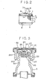
- An automotive radiator includes a plurality of tubes 1, end plates 3 and 4 connected at both ends of the tubes 1, an upper tank 5 which connects with the upper end plate 3 and a lower tank 6 which connects with the lower end plate 4, as shown in Fig. 2.
- Corrugate fins 2 are provided between adjacent pair of a plurality of tubes by welding so that the heat of the coolant passing through tube 1 is conducted to the corrugated fin in order to promote heat exchange.
- An inlet pipe 5 through which coolant from automotive engine (not shown) is introduced into the upper tank 5 and a filler neck 9 through which a coolant is rainforced to the upper tank 5 are provided on the upper tank 5 integrally.
- a connecting pipe 10 is provided on the filler neck 9 in order to connect the inside of the filler neck 9 to a reserve tank (not shown).
- a cap 100 is provided on the filler neck 9 in order to plug the filler neck 9.
- An outlet pipe 8 through which the coolant in the lower tank 6 flows to the engine is provided on the lower tank 6.
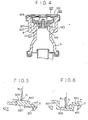
- the filler neck 9 has an inner tubular member 201 and an outer tubular member which provides at outside of the inner tubular member 201.
- a inner seal portion 202 is provided at the opening end of the inner tubular member, and an outer wall portion 204 is provided at the opening end of the outer tubular member 203.
- the outer seal portion 204 locates higher than the inner seal portion 202.
- a flange portion 205 is provided at the end portion of the outer tubular member in such a manner that the flange portion 205 elongates virtically outwardly.
- the cap 100 has an outer cap member 101 the outer periphery of which elongates downwardly to make a side wall 103, and the lower end of the side wall 103 elongates virtically inwardly to make a hook portion 105.
- the cap 100 is connected with the filler neck 9 when the hook portion 105 is contacted with the flange portion 205.
- the cap 100 can detouch from the filler neck 9 when the hook portion 105 locates at the notch portion at the flange portion 205.
- An inner cap member 107 is provided inner side of the outer cap member 101.
- the inner cap member has a wall portion 109 at the outer periphery thereof and a convex portion 101 which is provided at the inner side of the side wall portion 109.
- the outer cap member 101 has a port 102 at the center thereof, and the inner cap member 107 also has a concave portion 108 at the centrer thereof.
- the outer cap member 101 and the inner cap member 107 is connected each other by a connecting plate 103 which locates at the concave portion 108 and the port 102.
- the connecting plate 113 has a flange portion at the outer periphery thereof which connects around the port 10 2 of the outer cap member, the connecting plate 113 also has a center flat portion which is welded with the concave portion 108 of the inner cap member 107. So that the connecting plate 113 is fixed with the inner cap member 107. Since the outer cap member 101 is held between the flange portion of the connecting plate 103 and the inner cap member 107, the outer cap member 101 can rotate against the inner cap member 107 and the connecting plate 113.
- a leaf spring 114 is held between the outer cap member 101 and the inner cap member 107 in such a manner that the leaf spring 114 can rotate against the outer cap member 101 and the inner cap member 107.
- a ring shaped sealing member 115 made of readen is provided on the inner surface of the leaf spring so that the sealing member 115 sits on the outer seal portion 204 when the cap 100 is connected with the filler neck 9.
- a pressure valve 120 is provided inner side of the inner cap member 107 in such a manner that the cap shaped pressure valve 120 faces to the inner cap member 107.
- the pressure valve 120 has a bottom plate 121, a side wall portion 123 elongating virtically upwardly from the outer periphery of the bottom plate 121, a flat portion 12 5 elongating horizontally outwardly from the end portion of the side wall portion 123, a flange portion 127 elongating virtically upwardly from the outer perfear of the flat portion 125, and a hook portion 129 elongating horizontally outwardly from the end portion of the flange portion 127.
- the outer diameter of the bottom plate 121 and the side wall portion 123 is smaller than the inner diameter of the inner tubular member 201, and the bottom plate 121 and the side wall portion 123 locates within the inner tubular member 221.
- the outer diameter of the flat portion 125 is larger than the outer diameter of the inner tubular member 221, and a ring shaped sealing member 131 made of raisn is fixed on the lower side of the flat portion 121 so that the sealing member 131 sits on the inner sealing portion 202.
- the outer diameter of the flange portion 127 is slightly smaller than the inner diameter of the convex portion 111 of the inner cap member 107c and the outer diameter of the hook portion 129 is slightly smaller than the inner diameter of the side wall portion109 of the inner cap member so that the flange portion 127 and the hook portion 129 locates inside of the side wall portion 102 of the inner cap member 107 and that the pressure valve 120 can move virtically along with the side wall portion 109 of the inner cap member 107.
- the pressure valve 120 is connected with the inner cap member in such manner that the hook portion 129 is hooked by the conquave portion 111.
- a connecting hole is provided at the center of the bottom plate 121 and a center wall 133 is provided in the end plate 121 of the inner cap member 103 so that the center wall 133 forms the connecting hole therein.
- the sectional area of the connecting hole is reduced at the portion upper side of the central wall 133.
- a plurality of ribs 135 is formed at the flat plate 125, the side wall portion 123, the bottom plate 121 and the center wall 133 in order to increase the mechanical strength of the inner pressure valve 120.
- a coil spring 137 is provided between the inner cap member 107 and the pressure valve 120 so that the pressure valve 120 is forced toward the inner tubular member 201.
- One end of the coil spring 137 is contacted to the inner surface of the inner cap member, another end of the coil spring is contacted to the upper surface of the bottom plate 121.
- a pressure modulating valve 140 is provided at the lower surface of the bottom plate 120.
- the pressure modulating valve 140 has a flat portion 141 and a center rod 143 elongating upwardly from the centrer of the flat portion 141.
- a sealing member 143 is provided on the upper surface of the flat portion, and the sectional are of the center rod is reduced at the upper portion thereof so that the gap between the center rod 143 and the center wall 133 keeps same distance along with the longatuinal line of the center rod 143.
- a hook plate 145 is connected at the upper end portion of the center rod 143 so that the pressure modulating valve 140 is prevented to drop from the center wall 133.
- the connecting hole 150 is provided between the outer surface of the center rod 143 and the inner surface of the center wall 133.
- the connecting hole 150 is shut when the seal member 143 is sit on the under surface of the bottom plate 121, the bottom plate 121 is lifted by the pressure within the upper tank 5.
- the opening end 51 of the upper tank 5 is inserted into the groove provided at an outer perifear of the end plate 5 via an 0 ring 53.
- the end plate 3 and the upper tank 5 is connected each other by calk plate 55 when the calk plate is calked onto the edge of the opening end.
- the lower tank 6 is also connected with the end plate 4 by the calk plate.
- the pressure modulating valve 140 moves downwardly in order to open the sealing member 147 from the bottom portion 121 of the pressure valve 120 when the pressure within the upper tank 5 decreases lower than the atmospheric pressure. So that the coolant within the reserve tank is introduced to the upper tank through the pipe 10 and the connecting hole 110 which is provided between the center rod 143 of the pressure modulating pipe 140 and the center wall portion 133.
- the pressure modulating valve 140 moves upwardly in order to seal the bottom portion 121 of the pressure valve 120 when the pressure within the upper tank 5 increases higher than the atmospheric pressure. So that the connecting hole 150 is shut by the sealing member 147.
- the pressure valve 120 moves upwardly when the pressure in the upper tank 5 increases higher than the predetermined pressure of the coil spring 137.
- the sealing member 131 moves with the pressure valve 120 upwardly so that the inner seal portion 202 of the inner tubular member 201 is opened and the evaporated coolant within the upper tank 5 escape to the reserve tank through the groove formed between the outer tubular member 203 and the inner tubular member 201 and the pipe 10. Since the contacting point between the coil spring 137 and the bottom plate 121 of the pressure valve 120 locates lower than the-contacting point between the sealing member 131 and the inner sealing portion 202, the rotating moment M is generated on the the pressure valve 120 in order to make the pressure valve 120 horizontal when the pressure valve 120 inclines and partially opens the inner sealing portion 202.
- the pressure valve 120 of the present embodiment can maintain its position horizontally so that the high pressurized evaporated coolant within the upper tank 5 can escape to the groove formed between the inner tubular member 201 and the outer tubular member 203 through whole circumferencial periphery of the inner sealing portion 202. Accordingly, the pressure of the coolant when the coolant escaped the groove can be maintained under the predetermined pressure.
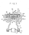
- the second embodiment of the present invention is explained hereinafter.
- the second embodiment of the present invention has a small spring 301 provided between the hook plate 145 and the pressure valve 120 and the center rod 143 of the pressure modulating valve 140 does pot vary the sectional area thereof along with the longatuinal axis thereof.
- the sealing member 147 is always forced toward the pressure valve 120 by a setting force of the small spring 301. Accordingly, the connecting hole 150 is opened when the pressure within the upper tank decreases so that the pressure forcing the pressure modulating valve 140 'downwardly becomes higher than the setting force of the small spring 301.
- sealing member 147 of the pressure modulating valve 140 of the first and second embodiment is a ring shaped, other shaped sealing member such as an O-ring can also be used for the sealing member as described in Fig. 4.
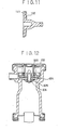
- the third embodiment of the present invention is explained hereinafter by refering Fig. 7.
- the center rod 143 of the pressure modulating valve 140 of the third embodiment has a larger diameter rod portion and a smaller diameter rod portion provided at the upper side of the larger diameter rod portion.
- the connecting hole 150 is provided between the outer surface of the smaller diameter rod portion of the center rod 143 and the inner surface of the center wall portion.
- a spring 148 is provided between the under surface of a hook portion 134 of the center wall 133 and shoulder portion of the center rod portion 143 in order to bias the pressure modulating valve 140 downwardly for opening the connecting hole.
- the pressure modulating valve 140 moves upwardly for closing the connecting hole when the pressure within the upper tank 5 increases higher than about 0.4 - 0.6 kglcm 2 . Since a water pump (not shown) which circulates the coolant rotates high speed when the engine is under accelerating or racing condition, the pressure within the upper tank 5 can increase up to about 0.4 - 0.6 kg/cm2 when the engine under such condition. Every other features of the third embodiment is the same as those of the above described first and second embodiments.
- the pressure modulating valve 140 of the present invention can open the connecting hole 150 even though the water pump rotates high speed under the condition when the engine is accelerating or racing. So that the pressure modulating valve 140 of the third embodiment can release the coolant within the upper tank 5 to the reserve tank through the connecting tank hole 150 effectively.
- the fourth embodiment of the present invention is explained hereinafter by refering Fig. 8.
- the pressure modulating valve 140 of the forth embodiment has the center rod 143 provided within the connecting hole 150, a disk portion provided at the lower end of the center rod 143, and the sealing member 147 provided at the upper end of the disk portion 142 in order to fit the pressure valve 120.
- the disk portion 142 of the fourth embodiment is made of bi-metal the projecting direction of which is changed at the predetermined temperature, and the disk portion 142 is connected with the center rod 143 at the center thereof.
- the disk portion 142 projects upwardly as shown in Fig. 8 when the temperature within the upper tank 5 is lower than the predetermined temperature so that the connecting hole 150 is opened.
- the disk portion 142 projects downwardly when the temperature within the upper tank 5 increases up to the predetermined temperature so that the disk portion 142 forces the sealing member 147 on to the pressure valve 120 in order to close the connecting hole 122.
- the predetermined pressure is said below the boiling point of the coolant within the upper tank 5 such as 80°C - 95°C.
- the shape memory alloy can be used for the disk portion 142 instead of the bi-metal.
- the coolant within the reserve tank can be introduced into the upper tank 5 through the pipe 10 and the connecting hole 150 when the the temperature of the coolant within the upper tank 5 is lower than the' predetermined temperature (80°C - 95°C).
- the connecting hole 150 is closed by the sealing member 147 when the disk portion 142 projects downwardly, namely when the temperature of the coolant within the upper tank 5 increases up to the predetermined temperature ( 80°C - 95°C).
- the coolant within the upper tank 5 can be escaped when the pressure of the coolant increases higher than the setting force of the coil spring 137.
- the pressure modulating valve of the fourth embodiment can open the connecting hole always under the condition when the temperature of the coolant within the upper tank 5 is lower than the predetermined temperature, the vibration of the pressure within the upper tank can be well prevented so that the pressure damage caused the upper tank 5 can be reduced.
- the disk plate 142 shown in Fig. 8 forces the sealing member 147 against the bottom plate 123 of the pressure valve 120 when. the disk plate 142 projects down wardly
- the disk plate 142 of the fourth embodiment can have a small gap between the bottom surface 123 of the pressure valve 120 and the upper surface of the sealing member 147 even when the disk portion 142 projects downwardly in order to open the connecting hole 150 when the temperature of the coolant within the upper tank 5 increases up to the predetermined pressure (70°C - 80°C).
- the connecting hole 150 of the modified embodiment of the fourth embodiment is closed when the pressure within the upper, tank 5 increases higher than the gravity of the pressure modulating valve 150.
- the fifth embodiment of the present, invention is explained hereinafter by refering Fig. 9.
- the pressure modulating valve 140 of the fifth embodiment has the center rod 143 and the flat portion 141 as shown in Figs. 10 and 11.
- a plurality of impellers 192 are provided at the upper side of the flat portion 142 so that the impellers 192 make the pressure modulating valve 140 rotate when the flow of the coolant passing through the connecting hole 150 collides thererto.
- the pressure modulating valve 140 moves downwardly by its gravity as shown in Fig. 9 in order to maintain the pressure within the upper tank 5 under the atmospheric pressure when the temperature of the coolant within the upper tank 5 is lower than the predetermined pressure.
- the coolant within the upper tank 5 can escape to the reserve tank through the connecting hole 150 and the pipe 10 when the temperature of the coolant increases and the depressure of the tank is also increases.
- the flow of the coolant passing through the connecting hole 150 makes the pressure modulating valve 140 rotate.
- the connecting hole 150 is closed by the pressure modulating valve 140 when the pressure attained on the lower surface of the flat portion 141 is greater than the gravity of the pressure modulating valve, and the coolant within the upper tank 5 escapes to the reserve tank by lifting the pressure valve 120.
- the coolant in the reserve tank can return to the upper tank 5 through the connecting tank 150 when the temperature and the pressure of the coolant within the upper tank 5 reduces.
- the flow of the coolant from the reserve tank to the upper tank 5 also rotates the pressure modulating valve 140.
- the pressure modulating. valve 140 of the fifth embodiment can be rotated by both flows of the coolant from the upper tank 5 to the reserve tank and from the reserve tank to the upper tank 5.
- the rotation of the pressure modulating valve 140 makes it hard for the object to be held between the pressure modulating valve 140 and the pressure valve 120, and also the rotation of the pressure modulating valve 140 can remove any objects between the pressure modulating valve 140 and the pressure valve 120.
Landscapes
- Engineering & Computer Science (AREA)
- Chemical & Material Sciences (AREA)
- Combustion & Propulsion (AREA)
- Mechanical Engineering (AREA)
- General Engineering & Computer Science (AREA)
- Transportation (AREA)
- Cooling, Air Intake And Gas Exhaust, And Fuel Tank Arrangements In Propulsion Units (AREA)
- Safety Valves (AREA)
- Closures For Containers (AREA)
Applications Claiming Priority (8)
| Application Number | Priority Date | Filing Date | Title |
|---|---|---|---|
| JP61090994A JPS62247115A (ja) | 1986-04-18 | 1986-04-18 | 自動車用ラジエ−タキヤツプ |
| JP90994/86 | 1986-04-18 | ||
| JP61171294A JPS6329011A (ja) | 1986-07-21 | 1986-07-21 | 自動車用ラジエ−タキャップ |
| JP171295/86 | 1986-07-21 | ||
| JP61171295A JPS6329012A (ja) | 1986-07-21 | 1986-07-21 | 自動車用ラジエ−タキヤツプ |
| JP171294/86 | 1986-07-21 | ||
| JP61239976A JPS6394018A (ja) | 1986-10-08 | 1986-10-08 | 熱交換器用キヤツプ |
| JP239976/86 | 1986-10-08 |
Related Child Applications (2)
| Application Number | Title | Priority Date | Filing Date |
|---|---|---|---|
| EP93118218.2 Division-Into | 1987-04-16 | ||
| EP93118219.0 Division-Into | 1987-04-16 |
Publications (3)
| Publication Number | Publication Date |
|---|---|
| EP0246450A2 true EP0246450A2 (de) | 1987-11-25 |
| EP0246450A3 EP0246450A3 (en) | 1989-02-22 |
| EP0246450B1 EP0246450B1 (de) | 1994-06-15 |
Family
ID=27467841
Family Applications (1)
| Application Number | Title | Priority Date | Filing Date |
|---|---|---|---|
| EP87105639A Expired - Lifetime EP0246450B1 (de) | 1986-04-18 | 1987-04-16 | Automobilkühlerdeckel |
Country Status (6)
| Country | Link |
|---|---|
| US (1) | US5052571A (de) |
| EP (1) | EP0246450B1 (de) |
| KR (1) | KR930000438B1 (de) |
| AU (1) | AU581365B2 (de) |
| CA (1) | CA1303023C (de) |
| DE (1) | DE3750054T2 (de) |
Families Citing this family (7)
| Publication number | Priority date | Publication date | Assignee | Title |
|---|---|---|---|---|
| USD363221S (en) | 1993-12-28 | 1995-10-17 | Puryear Larry A | Combined cap and funnel for use with automobile liquids |
| AT403144B (de) * | 1996-01-09 | 1997-11-25 | Blau Automobiltechnik Gmbh | Verschluss für einen einfüllstutzen, insbesondere eines fahrzeug-kraftstofftankes |
| US5741069A (en) * | 1996-04-16 | 1998-04-21 | Egel; Kenneth D. | Combined thermometer and radiator cap |
| JP4106820B2 (ja) * | 1999-07-14 | 2008-06-25 | 株式会社デンソー | 完全密閉型容器 |
| US6273286B1 (en) * | 2000-04-12 | 2001-08-14 | Evergreen Custom Molding, Inc. | Ventilating system |
| DE10037856A1 (de) * | 2000-08-01 | 2002-02-14 | Ibs Filtran Kunststoff Metall | Ölbehälter und Verfahren zu seiner Herstellung |
| CN106198371A (zh) * | 2016-07-12 | 2016-12-07 | 中国人民解放军第五七九工厂 | 一种新型橡胶耐油试验装置 |
Family Cites Families (18)
| Publication number | Priority date | Publication date | Assignee | Title |
|---|---|---|---|---|
| US2164450A (en) * | 1937-12-30 | 1939-07-04 | Gen Motors Corp | Radiator pressure cap |
| US2406502A (en) * | 1943-08-20 | 1946-08-27 | Stant Mfg Company | Radiator pressure cap |
| US2649986A (en) * | 1949-11-15 | 1953-08-25 | Anton W Konchan | Radiator pressure cap |
| US3053408A (en) * | 1960-09-08 | 1962-09-11 | Stant Mfg Company Inc | Radiator cap with safety gasket |
| US3189213A (en) * | 1961-12-18 | 1965-06-15 | Gen Motors Corp | Manual reset relief valve closure |
| US3203578A (en) * | 1962-02-28 | 1965-08-31 | Eaton Mfg Co | Clusure device |
| US3164288A (en) * | 1963-01-10 | 1965-01-05 | C J Boomgaard | Closure and valve construction |
| US3381846A (en) * | 1966-02-07 | 1968-05-07 | Wells Joe S | Radiator pressure cap |
| AU448728B2 (en) * | 1971-05-17 | 1974-05-10 | Saf-Gard Products, Inc | Cooling liquid system and method of operating a closed cooling liquid circuit foran internal combustion engine |
| AU461753B2 (en) * | 1971-10-29 | 1975-06-05 | Carl Avrea Walter | Monolithic radiator cap for sealed pressurized cooling system |
| US4196822A (en) * | 1971-10-29 | 1980-04-08 | Avrea Walter C | Monolithic radiator cap for sealed pressurized cooling system |
| US3910451A (en) * | 1973-10-01 | 1975-10-07 | Arthur P Tusing | Radiator cap |
| US4136795A (en) * | 1975-09-05 | 1979-01-30 | Stant Manufacturing Company, Inc. | Plastic radiator cap |
| US4185751A (en) * | 1978-07-31 | 1980-01-29 | Stant Manufacturing Company, Inc. | Radiator cap |
| AU525015B2 (en) * | 1978-09-15 | 1982-10-14 | A.S. Daly Nominees Pty. Ltd. | Radiator cap assembly |
| US4498599A (en) * | 1983-08-15 | 1985-02-12 | Avrea Walter C | Closure and valving apparatus |
| US4489883A (en) * | 1984-01-19 | 1984-12-25 | General Motors Corporation | Temperature regulated dual pressure device |
| CA1276011C (en) * | 1986-02-20 | 1990-11-06 | Nippondenso Co., Ltd. | Automotive radiator |
-
1987
- 1987-04-13 KR KR1019870003499A patent/KR930000438B1/ko not_active Expired - Lifetime
- 1987-04-16 AU AU71770/87A patent/AU581365B2/en not_active Expired
- 1987-04-16 EP EP87105639A patent/EP0246450B1/de not_active Expired - Lifetime
- 1987-04-16 CA CA000535039A patent/CA1303023C/en not_active Expired - Lifetime
- 1987-04-16 DE DE3750054T patent/DE3750054T2/de not_active Expired - Lifetime
-
1989
- 1989-06-02 US US07/363,375 patent/US5052571A/en not_active Expired - Lifetime
Also Published As
| Publication number | Publication date |
|---|---|
| EP0246450A3 (en) | 1989-02-22 |
| CA1303023C (en) | 1992-06-09 |
| AU7177087A (en) | 1987-10-22 |
| AU581365B2 (en) | 1989-02-16 |
| EP0246450B1 (de) | 1994-06-15 |
| DE3750054D1 (de) | 1994-07-21 |
| KR870009877A (ko) | 1987-11-30 |
| US5052571A (en) | 1991-10-01 |
| DE3750054T2 (de) | 1995-01-26 |
| KR930000438B1 (ko) | 1993-01-21 |
Similar Documents
| Publication | Publication Date | Title |
|---|---|---|
| US5738132A (en) | Roll over vent valve | |
| JP3098798B2 (ja) | 燃料蒸気逃がし弁 | |
| US4098328A (en) | Cross-flow radiator deaeration system | |
| EP0246450A2 (de) | Automobilkühlerdeckel | |
| EP1782992B1 (de) | Überrollventil mit Unterdrucksicherheitsfunktion | |
| US2249971A (en) | Cooling system pressure relief device | |
| CA2012947A1 (en) | Fin for a heat exchanger and heat exchanging system using the fin | |
| EP0581336B1 (de) | Kondensatableiter mit freiem Schwimmer | |
| US5169015A (en) | Vehicle radiator cap with auxiliary vacuum seal | |
| US3380619A (en) | Radiator cap | |
| US4809773A (en) | Automotive radiator | |
| GB2177498A (en) | Engine cooling system air venting arrangement with buoyant air purge valve | |
| JP3878248B2 (ja) | フロ―ト式スチ―ムトラップ | |
| CN216200122U (zh) | 一种升降式止回阀 | |
| JPH1030793A (ja) | フロ―ト式スチ―ムトラップ | |
| JP2503139B2 (ja) | 自動車用ラジエ―タキャップ | |
| JPH06280781A (ja) | 水中ポンプ | |
| JP5351706B2 (ja) | サーモスタット装置 | |
| JP4209698B2 (ja) | フロート式スチームトラップ | |
| JPH0438893B2 (de) | ||
| JP2961348B2 (ja) | フロ―ト式スチ―ムトラップ | |
| KR200147751Y1 (ko) | 차량용 라디에이터 | |
| JPH0325517Y2 (de) | ||
| JPH1061888A (ja) | フロ―ト式スチ―ムトラップ | |
| JPS5838317A (ja) | 内燃機関の冷却装置 |
Legal Events
| Date | Code | Title | Description |
|---|---|---|---|
| PUAI | Public reference made under article 153(3) epc to a published international application that has entered the european phase |
Free format text: ORIGINAL CODE: 0009012 |
|
| AK | Designated contracting states |
Kind code of ref document: A2 Designated state(s): DE FR GB IT |
|
| PUAL | Search report despatched |
Free format text: ORIGINAL CODE: 0009013 |
|
| AK | Designated contracting states |
Kind code of ref document: A3 Designated state(s): DE FR GB IT |
|
| 17P | Request for examination filed |
Effective date: 19890405 |
|
| 17Q | First examination report despatched |
Effective date: 19890720 |
|
| GRAA | (expected) grant |
Free format text: ORIGINAL CODE: 0009210 |
|
| AK | Designated contracting states |
Kind code of ref document: B1 Designated state(s): DE FR GB IT |
|
| XX | Miscellaneous (additional remarks) |
Free format text: TEILANMELDUNG 93118218.2 EINGEREICHT AM 16/04/87. |
|
| REF | Corresponds to: |
Ref document number: 3750054 Country of ref document: DE Date of ref document: 19940721 |
|
| ET | Fr: translation filed | ||
| ITF | It: translation for a ep patent filed | ||
| PLBE | No opposition filed within time limit |
Free format text: ORIGINAL CODE: 0009261 |
|
| STAA | Information on the status of an ep patent application or granted ep patent |
Free format text: STATUS: NO OPPOSITION FILED WITHIN TIME LIMIT |
|
| 26N | No opposition filed | ||
| REG | Reference to a national code |
Ref country code: GB Ref legal event code: IF02 |
|
| APAH | Appeal reference modified |
Free format text: ORIGINAL CODE: EPIDOSCREFNO |
|
| PGFP | Annual fee paid to national office [announced via postgrant information from national office to epo] |
Ref country code: FR Payment date: 20060410 Year of fee payment: 20 |
|
| PGFP | Annual fee paid to national office [announced via postgrant information from national office to epo] |
Ref country code: GB Payment date: 20060412 Year of fee payment: 20 |
|
| PGFP | Annual fee paid to national office [announced via postgrant information from national office to epo] |
Ref country code: DE Payment date: 20060413 Year of fee payment: 20 |
|
| PGFP | Annual fee paid to national office [announced via postgrant information from national office to epo] |
Ref country code: IT Payment date: 20060430 Year of fee payment: 20 |
|
| REG | Reference to a national code |
Ref country code: GB Ref legal event code: PE20 |
|
| PG25 | Lapsed in a contracting state [announced via postgrant information from national office to epo] |
Ref country code: GB Free format text: LAPSE BECAUSE OF EXPIRATION OF PROTECTION Effective date: 20070415 |