EP0245708A2 - Vorrichtung zur Schnellkühlung oder Schockfrostung von schüttfähigen Produkten - Google Patents
Vorrichtung zur Schnellkühlung oder Schockfrostung von schüttfähigen Produkten Download PDFInfo
- Publication number
- EP0245708A2 EP0245708A2 EP87106235A EP87106235A EP0245708A2 EP 0245708 A2 EP0245708 A2 EP 0245708A2 EP 87106235 A EP87106235 A EP 87106235A EP 87106235 A EP87106235 A EP 87106235A EP 0245708 A2 EP0245708 A2 EP 0245708A2
- Authority
- EP
- European Patent Office
- Prior art keywords
- drum
- product
- refrigerant
- drums
- inner drum
- Prior art date
- Legal status (The legal status is an assumption and is not a legal conclusion. Google has not performed a legal analysis and makes no representation as to the accuracy of the status listed.)
- Granted
Links
Images

Classifications
-
- F—MECHANICAL ENGINEERING; LIGHTING; HEATING; WEAPONS; BLASTING
- F25—REFRIGERATION OR COOLING; COMBINED HEATING AND REFRIGERATION SYSTEMS; HEAT PUMP SYSTEMS; MANUFACTURE OR STORAGE OF ICE; LIQUEFACTION SOLIDIFICATION OF GASES
- F25D—REFRIGERATORS; COLD ROOMS; ICE-BOXES; COOLING OR FREEZING APPARATUS NOT OTHERWISE PROVIDED FOR
- F25D3/00—Devices using other cold materials; Devices using cold-storage bodies
- F25D3/10—Devices using other cold materials; Devices using cold-storage bodies using liquefied gases, e.g. liquid air
- F25D3/11—Devices using other cold materials; Devices using cold-storage bodies using liquefied gases, e.g. liquid air with conveyors carrying articles to be cooled through the cooling space
-
- A—HUMAN NECESSITIES
- A23—FOODS OR FOODSTUFFS; TREATMENT THEREOF, NOT COVERED BY OTHER CLASSES
- A23L—FOODS, FOODSTUFFS, OR NON-ALCOHOLIC BEVERAGES, NOT COVERED BY SUBCLASSES A21D OR A23B-A23J; THEIR PREPARATION OR TREATMENT, e.g. COOKING, MODIFICATION OF NUTRITIVE QUALITIES, PHYSICAL TREATMENT; PRESERVATION OF FOODS OR FOODSTUFFS, IN GENERAL
- A23L3/00—Preservation of foods or foodstuffs, in general, e.g. pasteurising, sterilising, specially adapted for foods or foodstuffs
- A23L3/36—Freezing; Subsequent thawing; Cooling
- A23L3/37—Freezing; Subsequent thawing; Cooling with addition of or treatment with chemicals
- A23L3/375—Freezing; Subsequent thawing; Cooling with addition of or treatment with chemicals with direct contact between the food and the chemical, e.g. liquid nitrogen, at cryogenic temperature
-
- F—MECHANICAL ENGINEERING; LIGHTING; HEATING; WEAPONS; BLASTING
- F25—REFRIGERATION OR COOLING; COMBINED HEATING AND REFRIGERATION SYSTEMS; HEAT PUMP SYSTEMS; MANUFACTURE OR STORAGE OF ICE; LIQUEFACTION SOLIDIFICATION OF GASES
- F25D—REFRIGERATORS; COLD ROOMS; ICE-BOXES; COOLING OR FREEZING APPARATUS NOT OTHERWISE PROVIDED FOR
- F25D25/00—Charging, supporting, and discharging the articles to be cooled
- F25D25/04—Charging, supporting, and discharging the articles to be cooled by conveyors
-
- F—MECHANICAL ENGINEERING; LIGHTING; HEATING; WEAPONS; BLASTING
- F25—REFRIGERATION OR COOLING; COMBINED HEATING AND REFRIGERATION SYSTEMS; HEAT PUMP SYSTEMS; MANUFACTURE OR STORAGE OF ICE; LIQUEFACTION SOLIDIFICATION OF GASES
- F25D—REFRIGERATORS; COLD ROOMS; ICE-BOXES; COOLING OR FREEZING APPARATUS NOT OTHERWISE PROVIDED FOR
- F25D2400/00—General features of, or devices for refrigerators, cold rooms, ice-boxes, or for cooling or freezing apparatus not covered by any other subclass
- F25D2400/30—Quick freezing
Definitions
- the invention relates to a device according to the preamble of patent claim 1.
- the task is to freeze pourable products individually in a gentle and economical manner, without the parts freezing, freezing together or being pressed in during the freezing or cooling process.
- rack cabinets long-belt freezers or spiral freezers.
- Drum freezers are also known, in which the products to be treated are fed into a drum into which a refrigerant is sprayed at the same time.
- Such drum freezers have the disadvantage of a large overall length. There is also a risk that the refrigerant only comes into contact with one side of the product bed (the top).
- a device for quick freezing of products is known, from which the preamble of claim 1 is based.
- This known device has an outer drum into which the product feed device opens and in which the product is treated with the refrigerant. There is another drum inside the first drum. After the product has passed the first drum in the longitudinal direction, it is lifted at the end of the outer drum via driver elements into the upper drum area, from where it falls onto a slide that falls into the inner drum. The product passes through the inner drum in the opposite direction to the outer drum and leaves the inner drum at the same end of the device at which the product feed device is located. Both drums have separate drives.
- the invention has for its object to provide a device according to the preamble of claim 1, in which the product transfer from one drum to the other drum is simplified, and which ensures an economical implementation of treatment processes and an economical use of the refrigerant used.
- two drums arranged one inside the other are used which rotate individually or together.
- the pourable product is first fed into the inner drum, subjected to the cold treatment in it and transported further during the rotation of the drum tiert to fall into the outer drum after leaving the inner drum, where it is transported back in countercurrent.
- the product is transferred in that the product leaving the inner drum falls into the outer drum.
- a product lifting device is not required.
- the dwell time of the products in the inner drum can be influenced by deliberate product jam at the end of this inner drum. Such influencing can take place by bluff bodies or other internals which are provided at the outlet end of the inner drum.
- the location of the spray can be selected differently.
- the refrigerant is a gas that remains gaseous even in the expanded state
- the spraying is expediently carried out in the outer drum, ie in the return path of the product, the inner drum being used as a pre-cooling section.
- a gas is used as the refrigerant, which gives rise to snow during expansion, this gas should be sprayed as close as possible to the product inlet of the inner drum so that the snow is applied to the products as early as possible and these are transported all the way through both drums accompanied.
- the refrigerant is introduced into the inner drum, it becomes colder than the outer drum. As a result, the cold losses are reduced and the utilization of the refrigerant is improved.
- the invention enables better utilization of the cold by an improved way of the cold gas discharge, whereby the use of N2 is made possible as a refrigerant. It is not necessary to separate the product from the refrigerant.
- the product can be propelled either by the action of gravity, for which purpose the drum in question is designed with an axis inclined in the conveying direction, or by mechanical aids, such as helices or blades.
- mechanical propulsion means which are arranged on the drum walls, additional agitation of the product can be caused, whereby the risk of mutual freezing of the individual product parts is additionally counteracted.
- the diameter, speed, inclination and cross-sectional shape of the drums and the type and design of the internals can vary depending on the type of products to be treated and can be adapted to the cooling or rolling behavior of the products.
- the device according to the invention is not only suitable for freezing products, but for example also for cooling finished products, e.g. of diced chicken or dumplings and the like.
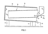
- the device shown in Fig. 1 has a first drum 10, which consists of a cylindrical tube open at the end faces, the axis of which is inclined relative to the horizontal in the conveying direction.
- the product inlet 11 is located at the higher end of the drum 10.
- a fixed introduction funnel 12 projects into this end.
- the first drum 10 is rotated about its longitudinal axis by a drive (not shown).
- the bulk material introduced into the drum is transported in the longitudinal direction due to the inclination of the drum due to the action of gravity.
- the bulk material leaves the second product outlet 11a, ie the end of the drum facing away from the product inlet, and falls into the interior of the second drum 13 which surrounds the first drum 10.
- the end of the second drum 13 arranged in the vicinity of the first product outlet 11a is closed by the end wall 14.
- the opposite end of the second drum 13 is open to form the product outlet 15.
- This drum end is arranged lower than the end wall 14, ie the second drum 13, which also rotates, is inclined in the opposite direction to the first drum 10.
- the bulk material leaving the second product outlet 15 falls into a container 16 or is fed to a packaging device.
- the bearing blocks of the second drum 13 are designated 17.
- the fixed refrigerant line 18 opens into the first drum 10.
- a refrigerant in the present case carbon dioxide (CO2) is sprayed under pressure into the first drum 10 from the refrigerant line 18.
- CO2 carbon dioxide
- the refrigerant turns into snow, which is deposited on the products. Due to the rolling movement inside the drum 10, the products are coated evenly with snow. As the path continues through the two drums 10 and 13, the product surface cools down on the snow coating.
- the first drum 10 is arranged coaxially and fixedly in the second drum 13.
- the product outlet 11a of the first drum 10 is axially spaced from the end wall 14 of the second drum.
- the walls of the two drums are continuous, i.e. they have no perforation.
- the common drum axis of both drums runs obliquely to the horizontal, the first product inlet 11 being arranged higher than the first product outlet 11a.
- spirals 20 and vanes are attached, which convey the product particles to the higher second product outlet 15 when the drums rotate.
- the refrigerant line 18 leads into the first drum 10 and the refrigerant (carbon dioxide) is sprayed shortly after the first product inlet 11.
- the product is filled into the introduction funnel 12 and metered into the first drum 10 by suitable adjustment of a slide 21.
- the product is advanced to the product outlet 11a, where it enters the second drum 13 exits.
- the product moves forward in countercurrent to the first drum, the transport being effected by the coils 20 or blades.
- Fig. 3 largely corresponds to that of Fig. 2, but instead of a snow-forming refrigerant a gaseous refrigerant (N2) is used.
- the peripheral wall of the inner drum 10 is perforated, i.e. it consists of a perforated wall or a grid.
- the fixed refrigerant line 18 protrudes outside of the inner drum 10 into the outer drum 13 and the refrigerant is sprayed at a considerable distance from the drum ends, for example in the central region of the drum length.
- the refrigerant initially reaches those product particles that are in the second drum 13, but also acts on the product particles located inside the drum 10 via the perforated wall of the drum 10.
- the heated refrigerant is finally sucked off through an exhaust pipe 23.
- the inner tube 10 acts as a pre-cooling section, while the actual frosting takes place in the outer tube 13 and outside the inner tube 10.
- the outer tube 13, including the end wall 14, is provided with a heat-insulating jacket 24.
- the drums 10 and 13 are each shown in the drawings as cylindrical tubes. There is also the possibility to change the cross-sectional shape of the drums in the longitudinal direction, so that cylindrical and poly alternate horizontal pipe sections. This ensures that the products are covered with CO2 snow all around and are frozen faster and more economically. In addition, the products are kept loose because they cannot freeze together due to the shaking.
Landscapes
- Engineering & Computer Science (AREA)
- Chemical & Material Sciences (AREA)
- Combustion & Propulsion (AREA)
- Physics & Mathematics (AREA)
- Mechanical Engineering (AREA)
- Thermal Sciences (AREA)
- General Engineering & Computer Science (AREA)
- General Chemical & Material Sciences (AREA)
- Chemical Kinetics & Catalysis (AREA)
- Health & Medical Sciences (AREA)
- Nutrition Science (AREA)
- Life Sciences & Earth Sciences (AREA)
- Food Science & Technology (AREA)
- Polymers & Plastics (AREA)
- Freezing, Cooling And Drying Of Foods (AREA)
- Meat, Egg Or Seafood Products (AREA)
- Carbon And Carbon Compounds (AREA)
Abstract
Description
- Die Erfindung betrifft eine Vorrichtung nach dem Oberbegriff des Patentanspruchs 1.
- In der Nahrungsmittelindustrie und in ähnlichen Bereichen besteht die Aufgabe, schüttfähige Produkte auf schonende und wirtschaftliche Weise einzeln zu frosten, ohne daß die Teile während des Frost- oder Kühlvorganges auf der Unterlage anfrieren, zusammenfrieren oder eingedrückt werden. Zur Durchführung der Schnellkühlung ist es bekannt, Hordenschränke, Langbandfroster oder Wendelfroster zu benutzen. Bekannt sind ferner Trommelfroster, bei denen die zu behandelnden Produkte in eine Trommel eingegeben werden, in die gleichzeitig ein Kältemittel eingesprüht wird. Solche Trommelfroster haben den Nachteil einer großen Baulänge. Außerdem besteht die Gefahr, daß das Kältemedium nur mit einer Seite der Produktschüttung (der Oberseite) in Kontakt kommt.
- Aus US-A-3 446 030 ist eine Vorrichtung zum schnellfrosten von Produkten bekannt, von der der Oberbegriff des Patenanspruchs 1 ausgeht. Diese bekannte Vorrichtung weist eine äußere Trommel auf, in die die Produkt-Zuführvorrichtung mündet und in der eine Behandlung des Produkts mit dem Kältemittel erfolgt. Im Innern der ersten Trommel befindet sich eine weitere Trommel. Nachdem das Produkt die erste Trommel in Längsrichtung passiert hat, wird es am Ende der äußeren Trommel über Mitnehmerelemente in den oberen Trommelbereich angehoben, von wo es auf eine Rutsche fällt, die in die innere Trommel hineinfällt. Das Produkt durchläuft die innere Trommel in Gegenrichtung zur äußeren Trommel und verläßt die innere Trommel an demselben Ende der Vorrichtung, an dem sich die Produkt-Zuführvorrichtung befindet. Beide Trommeln haben separate Antriebe.
- Der Erfindung liegt die Aufgabe zugrunde, eine Vorrichtung nach dem Oberbegriff des Patentanspruchs 1 zu schaffen, bei der die Produktübergabe von der einen Trommel in die andere Trommel vereinfacht ist, und die eine wirtschaftliche Durchführung von Behandlungsprozessen und eine wirtschaftliche Ausnutzung des eingesetzten Kältemittels gewährleistet.
- Die Lösung dieser Aufgabe erfolgt erfindungsgemäß mit den Merkmalen des kennzeichnenden Teils des Patentanspruchs 1.
- Nach der Erfindung werden zwei ineinander angeordnete Trommeln benutzt, die einzeln oder gemeinsam rotieren. Das schüttfähige Produkt wird zunächst in die innere Trommel geleitet, in dieser der Kältebehandlung ausgesetzt und während der Trommeldrehung weitertranspor tiert, um nach Verlassen der inneren Trommel in die äußere Trommel zu fallen, wo es im Gegenstrom zurücktransportiert wird. Bei der erfindungsgemäßen Vorrichtung erfolgt die Produktübergabe dadurch, daß das die innere Trommel verlassende Produkt in die äußere Trommel hereinfällt. Eine Produkt-Hebevorrichtung ist nicht erforderlich. Die Verweilzeit der Produkte in der inneren Trommel kann durch gezielten Produktstau am Ende dieser inneren Trommel beeinflußt werden. Eine solche Beeinflussung kann durch Staukörper oder andere Einbauten erfolgen, die am Auslaßende der inneren Trommel vorgesehen sind.
- In Abhängigkeit von der Art des eingesetzten Kältemittels kann der Ort der Einsprühung unterschiedlich gewählt werden. Wenn das Kältemittel ein Gas ist, das auch im expandierten Zustand gasförmig bleibt, erfolgt die Einsprühung zweckmäßigerweise in der äußeren Trommel, also im Rücklaufweg des Produktes, wobei die innere Trommel als Vorkühlstrecke benutzt wird. Wird als Kältemittel ein Gas verwendet, das bei der Expansion Schnee ergibt, dann sollte dieses Gas möglichst in der Nähe des Produkteinlasses der inneren Trommel versprüht werden, damit der Schnee möglichst frühzeitig auf die Produkte aufgetragen wird und diese auf ihrem gesamten Weg durch beide Trommeln hindurch begleitet. Bei Einbringung des Kältemittels in die innere Trommel wird diese kälter als die äußere Trommel. Dadurch werden die Kälteverluste verringert und die Ausnutzung des Kältemittels wird verbessert.
- Die Erfindung ermöglicht durch eine verbesserte Art der Kaltgas-Abführung eine bessere Kälteausnutzung, wodurch als Kältemittel die Verwendung von N₂ möglich gemacht wird. Eine Trennung des Produkts vom Kältemittel ist nicht erforderlich.
- Der Vortrieb des Produktes kann entweder durch Schwerkraftwirkung erfolgen, wozu die betreffende Trommel mit in Förderrichtung geneigter Achse ausgebildet ist, oder durch mechanische Hilfsmittel, wie Wendeln oder Flügel. Im Falle mechanischer Vortriebsmittel, die an den Trommelwänden angeordnet sind, kann eine zusätzliche Agitation des Produktes hervorgerufen werden, wodurch der Gefahr des gegenseitigen Anfrierens der einzelnen Produktteile zusätzlich entgegengewirkt wird.
- Durchmesser, Drehzahl, Neigung und Querschnittsform der Trommeln sowie die Art und Ausführung der Einbauten können in Abhängigkeit von der Art der zu behandelnden Produkte variieren und an das Kühl- oder Rollverhalten der Produkte angepaßt werden.
- Die erfindungsgemäße Vorrichtung eignet sich nicht nur zur Frostung von Produkten, sondern beispielsweise auch zur Kühlung von Fertigprodukten, z.B. von gewürfeltem Hühnerfleisch oder Klößchen und ähnlichem.
- Vorteilhafte Ausgestaltungen und Weiterbildungen der Erfindung sind in den Unteransprüchen angegeben.
- Im folgenden werden unter Bezugnahme auf die Zeichnungen Ausführungsbeispiele der Erfindung näher erläutert.
- Es zeigen:
- Fig. 1 einen schematischen Längsschnitt durch eine Vorrichtung mit zwei entgegengesetzt geneigten Trommeln,
- Fig. 2 eine Vorrichtung mit zwei koaxialen Trommeln, wobei das Kältemittel am Produkteinlaß der ersten Trommel eingesprüht wird, und
- Fig. 3 eine Vorrichtung mit zwei koaxialen Trommeln, wobei das Kältemittel in die äußere Trommel eingesprüht wird.
- Die in Fig. 1 dargestellte Vorrichtung weist eine erste Trommel 10 auf, die aus einem an den Stirnseiten offenen zylindrischen Rohr besteht, dessen Achse relativ zur Horizontalen in Förderrichtung geneigt ist. Der Produkteinlaß 11 befindet sich an dem höherliegenden Ende der Trommel 10. In dieses Ende ragt ein feststehender Einführtrichter 12 hinein. Die erste Trommel 10 wird von einem (nicht dargestellten) Antrieb um ihre Längsachse gedreht. Dabei wird das in die Trommel eingeführte Schüttgut infolge der Trommelneigung durch Schwerkraftwirkung in Längsrichtung transportiert. Das Schüttgut verläßt den zweiten Produktauslaß 11a, d.h. das dem Produkteinlaß abgewandte Trommelende, und fällt in das Innere der zweiten Trommel 13, welche die erste Trommel 10 umgibt. Das in der Nähe des ersten Produktauslasses 11a angeordnete Ende der zweiten Trommel 13 ist durch die Stirnwand 14 verschlossen. Das gegenüberliegende Ende der zweiten Trommel 13 ist zur Bildung des Produktauslasses 15 offen. Dieses Trommelende ist tiefer angeordnet als die Stirnwand 14, d.h. die zweite Trommel 13, die ebenfalls rotiert, ist in Gegenrichtung zur ersten Trommel 10 schräggestellt. Das den zweiten Produktauslaß 15 verlassende Schüttgut fällt in einen Behälter 16 oder wird einer Verpackungseinrichtung zugeführt. Die Lagerböcke der zweiten Trommel 13 sind mit 17 bezeichnet.
- In der Nähe des ersten Produkteinlasses 11 mündet die feststehende Kältemittelleitung 18 in die erste Trommel 10. Aus der Kältemittelleitung 18 wird ein Kältemittel, im vorliegenden Fall Kohlendioxid (CO₂) unter Druck in die erste Trommel 10 eingesprüht. Das Kältemittel wird bei der Expansion in Luft zu Schnee, der sich auf den Produkten ablagert. Infolge der Rollbewegung im Innern der Trommel 10 werden die Produkte gleichmäßig mit Schnee beschichtet. Im weiteren Verlauf des Weges durch die beiden Trommeln 10 und 13 kühlt sich die Produktoberfläche an der Schneebeschichtung ab.
- Bei dem Ausführungsbeispiel der Fig. 2 ist die erste Trommel 10 koaxial und fest in der zweiten Trommel 13 angeordnet. Der Produktauslaß 11a der ersten Trommel 10 befindet sich im axialen Abstand von der Stirnwand 14 der zweiten Trommel. Die Wände der beiden Trommeln sind durchgehend, d.h. sie haben keine Perforation. Die gemeinsame Trommelachse beider Trommeln verläuft schräg zur Horizontalen, wobei der erste Produkteinlaß 11 höher angeordnet ist als der erste Produktauslaß 11a. An der Innenseite der Umfangswand der zweiten Trommel 13 sind Wendeln 20 und Flügel angebracht, die die Produktteilchen bei Drehung der Trommeln zu dem höher liegenden zweiten Produktauslaß 15 fördern. Die Kältemittelleitung 18 führt in die erste Trommel 10 hinein und das Versprühen des Kältemittels (Kohlendioxid) erfolgt kurz hinter dem ersten Produkteinlaß 11.
- Das Produkt wird in den Einführtrichter 12 eingefüllt und durch geeignete Einstellung eines Schiebers 21 dosiert in die erste Trommel 10 eingegeben. In der drehenden Trommel 10 wird das Produkt bis zum Produktauslaß 11a fortbewegt, wo es in die zweite Trommel 13 hinein austritt. In der zweiten Trommel 13 erfolgt die Vorwärtsbewegung des Produktes im Gegenstrom zur ersten Trommel, wobei der Transport durch die Wendeln 20 oder Flügel bewirkt wird.
- Das Ausführungsbeispiel der Fig. 3 entspricht weitgehend demjenigen der Fig. 2, jedoch wird anstelle eines schneebildenden Kältemittels ein gasförmig bleibendes Kältemittel (N₂) benutzt. Die Umfangswand der inneren Trommel 10 ist perforiert, d.h. sie besteht aus einer Lochwand oder einem Gitter. Die feststehende Kältemittelleitung 18 ragt außerhalb der inneren Trommel 10 in die äußere Trommel 13 hinein und das Versprühen des Kältemittels erfolgt im erheblichen Abstand von den Trommelenden, beispielsweise im mittleren Bereich der Trommellänge. Das Kältemittel gelangt zunächst unmittelbar auf diejenigen Produktteilchen, die sich in der zweiten Trommel 13 befinden, wirkt jedoch über die perforierte Wand der Trommel 10 auch auf die im Innern der Trommel 10 befindlichen Produktteilchen. Das erwärmte Kältemittel wird schließlich durch ein Abgasrohr 23 abgesaugt. Bei dem Ausführungsbeispiel der Fig. 3 wirkt das innere Rohr 10 als Vorkühlstrecke, während die eigentliche Frostung im äußeren Rohr 13 und außerhalb des inneren Rohres 10 erfolgt.
- Bei allen beschriebenen Ausführungsbeispielen ist das äußere Rohr 13 einschließlich der Stirnwand 14 mit einem wärmeisolierenden Mantel 24 versehen.
- Die Trommeln 10 und 13 sind in den Zeichnungen jeweils als zylindrische Rohre dargestellt. Es besteht auch die Möglichkeit, die Querschnittsform der Trommeln in Längsrichtung zu verändern, so daß zylindrische und poly gonale Rohrabschnitte einander abwechseln. Dadurch wird erreicht, daß die Produkte rundum mit CO₂-Schnee behaftet und schneller und wirtschaftlicher durchfrostet werden. Außerdem werden die Produkte lose gehalten, weil sie durch die Schüttelung nicht aneinander festfrieren können.
Claims (8)
dadurch gekennzeichnet, daß die Produkt-Zuführvorrichtung (12) das Produkt dem ersten Produkteinlaß (11) der inneren Trommel (10) zuführt und daß der erste Produktauslaß (11a) im Innern der äußeren Trommel (13) derart angeordnet ist, daß das in verlassende Produkt in die äußere Trommel fällt.
Applications Claiming Priority (2)
| Application Number | Priority Date | Filing Date | Title |
|---|---|---|---|
| DE3616117 | 1986-05-13 | ||
| DE19863616117 DE3616117A1 (de) | 1986-05-13 | 1986-05-13 | Vorrichtung zur schnellkuehlung oder schockfrostung von schuettfaehigen produkten |
Publications (3)
| Publication Number | Publication Date |
|---|---|
| EP0245708A2 true EP0245708A2 (de) | 1987-11-19 |
| EP0245708A3 EP0245708A3 (en) | 1989-07-12 |
| EP0245708B1 EP0245708B1 (de) | 1992-04-01 |
Family
ID=6300745
Family Applications (1)
| Application Number | Title | Priority Date | Filing Date |
|---|---|---|---|
| EP87106235A Expired - Lifetime EP0245708B1 (de) | 1986-05-13 | 1987-04-29 | Vorrichtung zur Schnellkühlung oder Schockfrostung von schüttfähigen Produkten |
Country Status (3)
| Country | Link |
|---|---|
| EP (1) | EP0245708B1 (de) |
| DE (2) | DE3616117A1 (de) |
| DK (1) | DK165889C (de) |
Cited By (7)
| Publication number | Priority date | Publication date | Assignee | Title |
|---|---|---|---|---|
| EP0372354A2 (de) * | 1988-12-09 | 1990-06-13 | Air Products And Chemicals, Inc. | Gefriertunnel |
| GB2257240A (en) * | 1991-06-25 | 1993-01-06 | Boc Group Plc | Apparatus for chilling |
| FR2681314A1 (fr) * | 1991-09-16 | 1993-03-19 | Montagne Louis | Transporteurs rotatifs utilises notamment dans l'industrie du verre. |
| EP0857430A2 (de) * | 1997-01-15 | 1998-08-12 | Peter Heller GmbH | Vorrichtung zum Überziehen von Lebensmittelprodukten mit Sosse |
| DE4109900C2 (de) * | 1991-03-26 | 2000-01-13 | Linde Ag | Verfahren zur Kühlung von stückigem oder körnigem Gut |
| EP1306019A1 (de) * | 2000-08-04 | 2003-05-02 | Fuji Oil Company, Ltd. | Verfahren zur kontinuierlichen herstellung von gefrorenen lebensmitteln |
| CN112623648A (zh) * | 2020-12-18 | 2021-04-09 | 山东东铁铸锻有限公司 | 一种单线路锻球等温装置 |
Families Citing this family (2)
| Publication number | Priority date | Publication date | Assignee | Title |
|---|---|---|---|---|
| CN101780880A (zh) * | 2010-03-29 | 2010-07-21 | 西藏奇正藏药股份有限公司 | 一种冷却装置 |
| CN103879734A (zh) * | 2014-03-22 | 2014-06-25 | 辽阳顺通机械制造有限公司 | 一种螺旋输送冷却机 |
Citations (2)
| Publication number | Priority date | Publication date | Assignee | Title |
|---|---|---|---|---|
| US3304732A (en) * | 1965-12-29 | 1967-02-21 | Thermice Corp | Method and apparatus for chilling articles, especially food items |
| US3446030A (en) * | 1964-09-11 | 1969-05-27 | Thermice Corp | Method and apparatus for quick freezing individual food items |
-
1986
- 1986-05-13 DE DE19863616117 patent/DE3616117A1/de not_active Withdrawn
-
1987
- 1987-04-29 DE DE8787106235T patent/DE3777872D1/de not_active Expired - Fee Related
- 1987-04-29 EP EP87106235A patent/EP0245708B1/de not_active Expired - Lifetime
- 1987-05-12 DK DK238487A patent/DK165889C/da not_active IP Right Cessation
Patent Citations (2)
| Publication number | Priority date | Publication date | Assignee | Title |
|---|---|---|---|---|
| US3446030A (en) * | 1964-09-11 | 1969-05-27 | Thermice Corp | Method and apparatus for quick freezing individual food items |
| US3304732A (en) * | 1965-12-29 | 1967-02-21 | Thermice Corp | Method and apparatus for chilling articles, especially food items |
Cited By (14)
| Publication number | Priority date | Publication date | Assignee | Title |
|---|---|---|---|---|
| EP0372354A2 (de) * | 1988-12-09 | 1990-06-13 | Air Products And Chemicals, Inc. | Gefriertunnel |
| EP0372354A3 (de) * | 1988-12-09 | 1991-11-27 | Air Products And Chemicals, Inc. | Gefriertunnel |
| EP0519579A1 (de) * | 1988-12-09 | 1992-12-23 | Air Products And Chemicals, Inc. | Gefriertunnel |
| EP0519578A1 (de) * | 1988-12-09 | 1992-12-23 | Air Products And Chemicals, Inc. | Gefriertunnel |
| DE4109900C2 (de) * | 1991-03-26 | 2000-01-13 | Linde Ag | Verfahren zur Kühlung von stückigem oder körnigem Gut |
| AU654561B2 (en) * | 1991-06-25 | 1994-11-10 | Boc Group Plc, The | Apparatus for chilling |
| GB2257240B (en) * | 1991-06-25 | 1995-01-11 | Boc Group Plc | Apparatus for chilling |
| GB2257240A (en) * | 1991-06-25 | 1993-01-06 | Boc Group Plc | Apparatus for chilling |
| FR2681314A1 (fr) * | 1991-09-16 | 1993-03-19 | Montagne Louis | Transporteurs rotatifs utilises notamment dans l'industrie du verre. |
| EP0857430A2 (de) * | 1997-01-15 | 1998-08-12 | Peter Heller GmbH | Vorrichtung zum Überziehen von Lebensmittelprodukten mit Sosse |
| EP0857430A3 (de) * | 1997-01-15 | 1999-09-22 | Peter Heller GmbH | Vorrichtung zum Überziehen von Lebensmittelprodukten mit Sosse |
| EP1306019A1 (de) * | 2000-08-04 | 2003-05-02 | Fuji Oil Company, Ltd. | Verfahren zur kontinuierlichen herstellung von gefrorenen lebensmitteln |
| EP1306019A4 (de) * | 2000-08-04 | 2006-08-30 | Fuji Oil Co Ltd | Verfahren zur kontinuierlichen herstellung von gefrorenen lebensmitteln |
| CN112623648A (zh) * | 2020-12-18 | 2021-04-09 | 山东东铁铸锻有限公司 | 一种单线路锻球等温装置 |
Also Published As
| Publication number | Publication date |
|---|---|
| DK238487D0 (da) | 1987-05-12 |
| EP0245708B1 (de) | 1992-04-01 |
| DE3777872D1 (de) | 1992-05-14 |
| DK165889B (da) | 1993-02-01 |
| DE3616117A1 (de) | 1987-11-19 |
| EP0245708A3 (en) | 1989-07-12 |
| DK165889C (da) | 1993-06-28 |
| DK238487A (da) | 1987-11-14 |
Similar Documents
| Publication | Publication Date | Title |
|---|---|---|
| DE2421667C2 (de) | Vorrichtung zum Gefrieren von Material | |
| DE69824232T2 (de) | Gefriergerät | |
| EP0857430A2 (de) | Vorrichtung zum Überziehen von Lebensmittelprodukten mit Sosse | |
| DE3616630A1 (de) | Kuehlvorrichtung | |
| DE19708580A1 (de) | Behandlungsvorrichtung zum Behandeln von Erzeugnissen unter Einsatz eines gasförmigen Behandlungsmediums mit einem Förderer sowie Verfahren zum Betreiben derselben | |
| DE2337549A1 (de) | Verfahren und einrichtung zum gefriertrocknen | |
| DE2635945C2 (de) | Verfahren und Vorrichtung zum Inberührungbringen von, hauptsächlich schüttfähigen, festen Materialien mit Materialien im festen, flüssigen oder gasförmigen Aggregatzustand | |
| EP0245708B1 (de) | Vorrichtung zur Schnellkühlung oder Schockfrostung von schüttfähigen Produkten | |
| DE1501328A1 (de) | Verfahren und Vorrichtung zur Schnellgefrierung einzelner Nahrungsmittelgegenstaende | |
| EP0919279B1 (de) | Verfahren und Vorrichtung zum Pelletieren oder Granulieren eines flüssigen oder pastösen Stoffes | |
| EP0641522A2 (de) | Verfahren und Vorrichtung zum Pellet-Gefrieren von schütt und fliessfähigen Stoffen | |
| EP2522935A2 (de) | Vorrichtung zum Pelletieren oder Granulieren eines flüssigen oder pastösen Stoffes | |
| EP0549656B1 (de) | Verfahren und anlage zum reduktionsglühen von eisenpulver | |
| EP3433552B1 (de) | Vorrichtung zum dosieren von kohlendioxidschnee | |
| AT404361B (de) | Verfahren und vorrichtung zum abkühlen von heissem eisenschwamm | |
| DE1501329A1 (de) | Verfahren und Vorrichtung zum Kuehlen von Gegenstaenden,insbesondere Nahrungsmittelgegenstaenden | |
| EP1705439B1 (de) | Fahrbare Kühlvorrichtung | |
| DE2952403C2 (de) | Verfahren und Vorrichtung zum Aufbereiten, insb. Kühlen und Mischen von Formsand | |
| DE2346379C2 (de) | Anlage zum Gefrieren von Lebensmitteln und ähnlichen Produkten | |
| EP0242619A2 (de) | Verfahren und Vorrichtung zum Kühlen | |
| DE3915751C2 (de) | Verfahren zur Bindebehandlung von Fleischteilen | |
| DE2363716A1 (de) | Verfahren und vorrichtung zum scharfen abkuehlen von nahrungsmitteln | |
| EP0611928A1 (de) | Kühlung stückigen oder körnigen Gutes | |
| DE2721782A1 (de) | Kornfrucht-umwaelz-lagereinrichtung, insbesondere fuer getreide o.dgl. | |
| DE3522684A1 (de) | Behandlungsvorrichtung fuer die vorbehandlung von reis, rohreis od.dgl. |
Legal Events
| Date | Code | Title | Description |
|---|---|---|---|
| PUAI | Public reference made under article 153(3) epc to a published international application that has entered the european phase |
Free format text: ORIGINAL CODE: 0009012 |
|
| AK | Designated contracting states |
Kind code of ref document: A2 Designated state(s): BE CH DE FR GB IT LI NL SE |
|
| PUAL | Search report despatched |
Free format text: ORIGINAL CODE: 0009013 |
|
| AK | Designated contracting states |
Kind code of ref document: A3 Designated state(s): BE CH DE FR GB IT LI NL SE |
|
| 17P | Request for examination filed |
Effective date: 19890607 |
|
| 17Q | First examination report despatched |
Effective date: 19900702 |
|
| GRAA | (expected) grant |
Free format text: ORIGINAL CODE: 0009210 |
|
| AK | Designated contracting states |
Kind code of ref document: B1 Designated state(s): BE CH DE FR GB IT LI NL SE |
|
| ITF | It: translation for a ep patent filed |
Owner name: ING. A. GIAMBROCONO & C. S.R.L. |
|
| REF | Corresponds to: |
Ref document number: 3777872 Country of ref document: DE Date of ref document: 19920514 |
|
| ET | Fr: translation filed | ||
| GBT | Gb: translation of ep patent filed (gb section 77(6)(a)/1977) | ||
| PLBE | No opposition filed within time limit |
Free format text: ORIGINAL CODE: 0009261 |
|
| STAA | Information on the status of an ep patent application or granted ep patent |
Free format text: STATUS: NO OPPOSITION FILED WITHIN TIME LIMIT |
|
| 26N | No opposition filed | ||
| EAL | Se: european patent in force in sweden |
Ref document number: 87106235.2 |
|
| REG | Reference to a national code |
Ref country code: GB Ref legal event code: IF02 |
|
| PGFP | Annual fee paid to national office [announced via postgrant information from national office to epo] |
Ref country code: SE Payment date: 20030404 Year of fee payment: 17 |
|
| PGFP | Annual fee paid to national office [announced via postgrant information from national office to epo] |
Ref country code: FR Payment date: 20030408 Year of fee payment: 17 |
|
| PGFP | Annual fee paid to national office [announced via postgrant information from national office to epo] |
Ref country code: GB Payment date: 20030423 Year of fee payment: 17 |
|
| PGFP | Annual fee paid to national office [announced via postgrant information from national office to epo] |
Ref country code: NL Payment date: 20030429 Year of fee payment: 17 |
|
| PGFP | Annual fee paid to national office [announced via postgrant information from national office to epo] |
Ref country code: CH Payment date: 20030502 Year of fee payment: 17 |
|
| PGFP | Annual fee paid to national office [announced via postgrant information from national office to epo] |
Ref country code: DE Payment date: 20030508 Year of fee payment: 17 |
|
| PGFP | Annual fee paid to national office [announced via postgrant information from national office to epo] |
Ref country code: BE Payment date: 20030617 Year of fee payment: 17 |
|
| PG25 | Lapsed in a contracting state [announced via postgrant information from national office to epo] |
Ref country code: GB Free format text: LAPSE BECAUSE OF NON-PAYMENT OF DUE FEES Effective date: 20040429 |
|
| PG25 | Lapsed in a contracting state [announced via postgrant information from national office to epo] |
Ref country code: SE Free format text: LAPSE BECAUSE OF NON-PAYMENT OF DUE FEES Effective date: 20040430 Ref country code: LI Free format text: LAPSE BECAUSE OF NON-PAYMENT OF DUE FEES Effective date: 20040430 Ref country code: CH Free format text: LAPSE BECAUSE OF NON-PAYMENT OF DUE FEES Effective date: 20040430 Ref country code: BE Free format text: LAPSE BECAUSE OF NON-PAYMENT OF DUE FEES Effective date: 20040430 |
|
| BERE | Be: lapsed |
Owner name: *KOHLENSAUREWERK DEUTSCHLAND G.M.B.H. Effective date: 20040430 |
|
| PG25 | Lapsed in a contracting state [announced via postgrant information from national office to epo] |
Ref country code: NL Free format text: LAPSE BECAUSE OF NON-PAYMENT OF DUE FEES Effective date: 20041101 |
|
| PG25 | Lapsed in a contracting state [announced via postgrant information from national office to epo] |
Ref country code: DE Free format text: LAPSE BECAUSE OF NON-PAYMENT OF DUE FEES Effective date: 20041103 |
|
| EUG | Se: european patent has lapsed | ||
| REG | Reference to a national code |
Ref country code: CH Ref legal event code: PL |
|
| GBPC | Gb: european patent ceased through non-payment of renewal fee |
Effective date: 20040429 |
|
| PG25 | Lapsed in a contracting state [announced via postgrant information from national office to epo] |
Ref country code: FR Free format text: LAPSE BECAUSE OF NON-PAYMENT OF DUE FEES Effective date: 20041231 |
|
| NLV4 | Nl: lapsed or anulled due to non-payment of the annual fee |
Effective date: 20041101 |
|
| REG | Reference to a national code |
Ref country code: FR Ref legal event code: ST |
|
| PG25 | Lapsed in a contracting state [announced via postgrant information from national office to epo] |
Ref country code: IT Free format text: LAPSE BECAUSE OF NON-PAYMENT OF DUE FEES;WARNING: LAPSES OF ITALIAN PATENTS WITH EFFECTIVE DATE BEFORE 2007 MAY HAVE OCCURRED AT ANY TIME BEFORE 2007. THE CORRECT EFFECTIVE DATE MAY BE DIFFERENT FROM THE ONE RECORDED. Effective date: 20050429 |