EP0245634A2 - Dispositif pour le traitement ultérieur d'une bande continue couchée ou imprimée - Google Patents
Dispositif pour le traitement ultérieur d'une bande continue couchée ou imprimée Download PDFInfo
- Publication number
- EP0245634A2 EP0245634A2 EP87104697A EP87104697A EP0245634A2 EP 0245634 A2 EP0245634 A2 EP 0245634A2 EP 87104697 A EP87104697 A EP 87104697A EP 87104697 A EP87104697 A EP 87104697A EP 0245634 A2 EP0245634 A2 EP 0245634A2
- Authority
- EP
- European Patent Office
- Prior art keywords
- cooling roller
- material web
- squeegee
- cooling
- doctor
- Prior art date
- Legal status (The legal status is an assumption and is not a legal conclusion. Google has not performed a legal analysis and makes no representation as to the accuracy of the status listed.)
- Granted
Links
- 238000001816 cooling Methods 0.000 claims abstract description 54
- 239000002904 solvent Substances 0.000 claims abstract description 36
- 239000000463 material Substances 0.000 claims description 21
- 238000001704 evaporation Methods 0.000 claims description 6
- 230000008020 evaporation Effects 0.000 claims description 5
- 238000005266 casting Methods 0.000 claims description 2
- 229920001971 elastomer Polymers 0.000 claims description 2
- 239000000806 elastomer Substances 0.000 claims description 2
- 239000011347 resin Substances 0.000 claims description 2
- 229920005989 resin Polymers 0.000 claims description 2
- 238000010438 heat treatment Methods 0.000 claims 1
- 238000007639 printing Methods 0.000 abstract description 11
- 238000007645 offset printing Methods 0.000 abstract description 3
- 230000015572 biosynthetic process Effects 0.000 abstract description 2
- 238000000034 method Methods 0.000 abstract description 2
- 239000000976 ink Substances 0.000 description 10
- 238000007664 blowing Methods 0.000 description 3
- 239000003973 paint Substances 0.000 description 3
- 238000009792 diffusion process Methods 0.000 description 2
- 230000000694 effects Effects 0.000 description 2
- 238000000889 atomisation Methods 0.000 description 1
- 230000000903 blocking effect Effects 0.000 description 1
- 238000004140 cleaning Methods 0.000 description 1
- 238000006073 displacement reaction Methods 0.000 description 1
- 238000001035 drying Methods 0.000 description 1
- 238000002474 experimental method Methods 0.000 description 1
- 210000004602 germ cell Anatomy 0.000 description 1
- 230000003993 interaction Effects 0.000 description 1
- 230000003449 preventive effect Effects 0.000 description 1
Images

Classifications
-
- F—MECHANICAL ENGINEERING; LIGHTING; HEATING; WEAPONS; BLASTING
- F26—DRYING
- F26B—DRYING SOLID MATERIALS OR OBJECTS BY REMOVING LIQUID THEREFROM
- F26B25/00—Details of general application not covered by group F26B21/00 or F26B23/00
- F26B25/04—Agitating, stirring, or scraping devices
-
- F—MECHANICAL ENGINEERING; LIGHTING; HEATING; WEAPONS; BLASTING
- F26—DRYING
- F26B—DRYING SOLID MATERIALS OR OBJECTS BY REMOVING LIQUID THEREFROM
- F26B13/00—Machines and apparatus for drying fabrics, fibres, yarns, or other materials in long lengths, with progressive movement
- F26B13/10—Arrangements for feeding, heating or supporting materials; Controlling movement, tension or position of materials
- F26B13/14—Rollers, drums, cylinders; Arrangement of drives, supports, bearings, cleaning
- F26B13/18—Rollers, drums, cylinders; Arrangement of drives, supports, bearings, cleaning heated or cooled, e.g. from inside, the material being dried on the outside surface by conduction
Definitions
- the invention relates to a device for the aftertreatment of an at least one-sided coated or printed material web according to the preamble of claim 1.
- Post-treatment of such good webs is carried out with the aim of accelerating the volatilization of the solvents contained in printing inks and drying the printing inks to such an extent that the quality of the printed image is maintained during subsequent manipulations with the good web, for example in a folder.
- the gut web passes through a dryer in which the gut web is heated, and an adjoining vapor duct with a blower nozzle arrangement, which in the vapor duct has an air flow opposite the direction of passage of the gut web generated.
- the material web is then guided over a cooling roller arrangement, the cooling effect of which is intended to solidify the printing ink.
- the aim here is to reduce the concentration of the solvent in the air surrounding the material web before the material web reaches the cooling roller arrangement, on which larger amounts of solvent would otherwise condense.
- a blowing device is also provided, the air flow of which, in the vicinity of a cooling roller, is directed toward the surface of the material web facing away from the cooling roller and essentially in the radial direction toward the cooling roller.
- This is intended to force an intimate contact between the material web and the chill roll, in order to avoid an air gap that would otherwise occur between them, into which solvent still present can evaporate, and to cause the material temperature to drop rapidly below the evaporation point of the solvent with the aim that the small amounts of condensate still to be reabsorbed by the gut web and do not accumulate on the chill roll.
- the invention has for its object to provide a device of the type mentioned, which is particularly suitable for high web speeds. This object is achieved with a device according to claim 1.
- a web offset printing press can also be used with a doctor device arranged according to the invention even with strong ink occupancy with good web speeds over 6.5 meters per second, without solvent condensates having a negative impact on the print quality.
- a doctor device arranged according to the invention even with strong ink occupancy with good web speeds over 6.5 meters per second, without solvent condensates having a negative impact on the print quality.
- no efforts are required, as set out in the aforementioned DE-OS 33 05 749, in order to displace the air gap which arises between the material web and the cooling roll and into which solvent can evaporate.
- the path is taken instead of taking further preventive measures against the formation of condensate on the first cooling roll in order to avoid the disadvantageous consequences thereof and to use the simplest possible means for this purpose.
- the good web 1 is preferably a paper web printed on both sides, which has passed through the printing units of a web offset printing press.
- the paper web is then heated in dryer 2.
- Such dryers can be connected to a suction device with which solvent vapors are drawn off which emerge from the heated ink layer of the printed paper web.
- the paper web passes through a slot in a wall of the dryer adjoining the extractor duct 3 into the extractor duct.
- blocking nozzles 4 are provided, from which hot air is blown into the dryer through the slot.
- the paper web entering the vapor duct when hot continues to emit solvent, some of which can be drawn off via the vapor extractor 5.
- Another part is transported on with the paper web, on which a boundary layer of solvent-containing air with a relatively high solvent concentration is formed as a result of post-evaporation of solvents from deeper layers of paint.
- this boundary layer is partially reduced with the aid of blowing nozzles 6, with which one essentially opposes the direction of travel of the paper web directed blow air flow is directed at this.
- a complete "breaking up" of this boundary layer does not succeed, however, so that the paper web is still surrounded by solvent vapors when it hits the first cooling roller 7.
- An air gap is formed between the surface of the paper web that wraps around this cooling roller and the surface of the cooling roller, reinforced at higher web speeds.
- the cited pneumatic displacement requires a powerful blower, which increases the operating costs of a printing press not insignificantly, and it causes unsustainable atomization of the printing press and its Environment with solvents.
- an arrangement is shown which prevents the emission of harmful solvent vapors to the machine and in particular also into the machine hall.
- the invention makes use of a doctor device assigned to the first cooling roller, which, in an incredibly simple and effective manner, already markedly reduces the solvent concentration of the ink layer facing the first cooling roller on this cooling roller.
- the solvent condensate precipitated on the first cooling roller 7 is scraped off into a collecting container 9, from which it can be discharged in a controlled manner via a discharge nozzle 10.
- the doctored solvent is desirably lost to the further process insofar as it would otherwise be conveyed back by the rotating cooling roller into the air gap between the latter and the paper web without being doctored. This would have the consequence that a condensation-diffusion equilibrium would occur in the air gap at a higher solvent concentration in the color layer, which would counteract the evaporation of solvents from deeper color layers.
- the run of the paper web running from the first cooling roller would therefore still have a relatively high proportion of solvent in the deeper layers of the ink layer facing the cooling roller without being doctored.
- a doctor device with the purpose explained above is only provided on the first cooling roller.
- its total length must be kept as short as possible. This necessitates short paths of the paper web from the dryer to the first cooling roller and, especially at higher paper web speeds, extremely short periods of time which are available to the ink for reducing its solvent content.
- cooling and evaporation take place on the one hand without interaction with solvent condensate deposited on the first cooling roller and on the other hand over a longer period of time until the second cooling roller 11 (FIG. 1) is reached. .
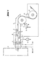
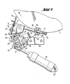
- FIG. 2 shows an exemplary embodiment of a doctor device arranged on the first cooling roller according to the invention. It has a replaceable squeegee bar 14 screwed onto the inside of the collecting container 9 (screws l3), which can be swiveled from the cooling roller 7 and adjusted against it by means of a swiveling device l6 actuated by an actuating cylinder l5. The contact pressure between the squeegee strip and the cooling roller can be adjusted on the spring l7 with the aid of the adjusting nut 25.
- a pull rod 28 is articulated on the swivel part 26.
- this pull rod By means of this pull rod, the squeegee strip is pressed against the cooling roller 7 by the spring 17 under an adjustable contact force.
- this spring is supported on an angle 29 fastened on the lever 20 and is placed at its other end against the adjusting nut 25.
- FIG. 3 shows a traversing device for the doctor device shown in FIG. 2. (Compared to their positions shown in FIG. 2, the traversing axis 23, the lever 20, the pivoting part 26 and the pull rod 28 are shown in different angular positions in FIG. 3 for better clarity.)
- the length of the squeegee strip 14 is dimensioned such that when it is traversed, at least the jacket region of the cooling roll which is used by the paper web is coated in each of its positions. This length is then at least twice the traversing path greater than the width of the paper web.
- the traversing movement is accomplished by means of a traversing cylinder 3l which is clamped between a fork 32 clamped on the traversing axis and the bracket 2l.
- the traversing cylinder is actuated via valves and control lines (not shown), the stroke limitation being effected via limit switches 33 which are attached to the traversing axis and with interact with a stop 34 connected to the axis l9.
- the traversing axis 23 is mounted in a longitudinally displaceable manner in the tabs 2l by means of bearing bushes 35. (Only one of the two brackets arranged near the ends of the axes is shown.)
- the swivel part 26 is arranged so that it cannot move in the longitudinal direction of the traversing axis and is connected to one end of the pull rod 28 via an articulated rod head 36.
- the spring l7 pushed on at the other end of the pull rod is supported on the angle 29 by means of a spherical disk 37.
- the doctor bar 14 is provided in the contact area with the cooling roller 7 with a vulcanized-on elastomer casting resin. This allows a satisfactory service life of the squeegee to be achieved. If necessary, squeegee strips that are worn out can be replaced with new ones by their detachable screw connection to the collecting container. For appropriate service work as well as for cleaning the collecting container, the entire doctor device can be pivoted away from the cooling roller in the manner described above. The collecting container 9 can be removed from the machine after loosening the screws 27.
Landscapes
- Engineering & Computer Science (AREA)
- Mechanical Engineering (AREA)
- General Engineering & Computer Science (AREA)
- Textile Engineering (AREA)
- Supply, Installation And Extraction Of Printed Sheets Or Plates (AREA)
- Application Of Or Painting With Fluid Materials (AREA)
Applications Claiming Priority (2)
| Application Number | Priority Date | Filing Date | Title |
|---|---|---|---|
| DE19863614742 DE3614742A1 (de) | 1986-04-30 | 1986-04-30 | Einrichtung zur nachbehandlung einer beschichteten oder bedruckten gutbahn |
| DE3614742 | 1986-04-30 |
Publications (3)
| Publication Number | Publication Date |
|---|---|
| EP0245634A2 true EP0245634A2 (fr) | 1987-11-19 |
| EP0245634A3 EP0245634A3 (en) | 1988-07-20 |
| EP0245634B1 EP0245634B1 (fr) | 1991-06-12 |
Family
ID=6299937
Family Applications (1)
| Application Number | Title | Priority Date | Filing Date |
|---|---|---|---|
| EP87104697A Expired - Lifetime EP0245634B1 (fr) | 1986-04-30 | 1987-03-31 | Dispositif pour le traitement ultérieur d'une bande continue couchée ou imprimée |
Country Status (6)
| Country | Link |
|---|---|
| US (1) | US4852492A (fr) |
| EP (1) | EP0245634B1 (fr) |
| JP (1) | JPS62263052A (fr) |
| CN (1) | CN1004543B (fr) |
| CA (1) | CA1284028C (fr) |
| DE (1) | DE3614742A1 (fr) |
Cited By (1)
| Publication number | Priority date | Publication date | Assignee | Title |
|---|---|---|---|---|
| EP3702164A1 (fr) * | 2019-03-01 | 2020-09-02 | Ricoh Company, Ltd. | Appareil, unité d'entrée d'air et appareil de sortie de liquide |
Families Citing this family (15)
| Publication number | Priority date | Publication date | Assignee | Title |
|---|---|---|---|---|
| DE3723400C1 (de) * | 1987-07-15 | 1989-02-23 | Baldwin Gegenheimer Gmbh | Verfahren und Vorrichtung zum Reinigen von Zylindern einer Rollendruckmaschine |
| DE9116646U1 (de) * | 1991-06-07 | 1993-06-03 | Eltex-Elektrostatik GmbH, 7858 Weil | Vorrichtung zur Erhöhung des Wärmeübergangs an Kühlwalzen von Offset-Rollenrotationsmaschinen |
| US5167189A (en) * | 1991-11-08 | 1992-12-01 | Jones Phillip W | Cylinder impurity remover apparatus |
| DE4325725C2 (de) * | 1993-07-30 | 1998-02-19 | Cleanpack Gmbh Innovative Verp | Verfahren und Vorrichtung zum Aufwickeln von im Rollen-Offsetdruck bedruckten Folienbahnen |
| WO1995015854A1 (fr) * | 1993-12-11 | 1995-06-15 | Eltex-Elektrostatik Gmbh | Procede et dispositif pour produire des feuilles imprimees |
| DE4409954A1 (de) * | 1994-03-23 | 1995-09-28 | Bse Printtechnologie | Kühlwalzenanordnung einer Rollenoffset-Druckmaschine |
| ATE168352T1 (de) * | 1994-09-02 | 1998-08-15 | Heidelberger Druckmasch Ag | Leiteinrichtung für einen bogen |
| DE19615198C1 (de) * | 1996-04-17 | 1997-07-24 | Grafotec Gmbh | Vorrichtung zur Rückbefeuchtung einer Bedruckstoffbahn |
| ITMI20031131A1 (it) * | 2003-06-05 | 2004-12-06 | Omet Srl | Metodo e dispositivo per la pulizia di un cilindro di |
| US20060096121A1 (en) * | 2004-11-05 | 2006-05-11 | Yugen Kaisha Advanced Engineering | Ink drying device of web offset press |
| DE102006027146B4 (de) * | 2006-06-12 | 2009-06-04 | Koenig & Bauer Aktiengesellschaft | Verfahren zur Herabsetzung der benötigten Kühlleistung in einem Kühlwalzenständer einer Rollenrotationsdruckmaschine und eine Vorrichtung in einem Kühlwalzenständer mit Kühlwalzen |
| JP5745830B2 (ja) * | 2010-12-06 | 2015-07-08 | 住友理工株式会社 | 固形天然ゴムの製造方法および製造装置 |
| CN104908408B (zh) * | 2015-06-08 | 2017-06-16 | 温州顺威包装有限公司 | 一种四色印刷机 |
| CN109028875A (zh) * | 2018-07-25 | 2018-12-18 | 赣州市翔义科技有限公司 | 一种服装面料用具有烘干除尘功能的清理装置 |
| CN114812140A (zh) * | 2022-05-11 | 2022-07-29 | 徐亿强 | 一种具有自动输送功能的纺织烘干装置 |
Citations (4)
| Publication number | Priority date | Publication date | Assignee | Title |
|---|---|---|---|---|
| DE1042611B (de) * | 1943-03-27 | 1958-11-06 | Edmund Arthur Rogge | Schwenkbar gelagerte Rakel einer Tiefdruckmaschine |
| DE2716613A1 (de) * | 1977-04-15 | 1978-10-19 | Vits Maschinenbau Gmbh | Vorrichtung zum trocknen einer bedruckten oder beschichten inbesondere aus papier bestehenden warenbahn |
| AT351051B (de) * | 1972-02-09 | 1979-07-10 | Daetwyler & Co M | Rakelblatt fuer tiefdruckmaschinen |
| DE3305749A1 (de) * | 1982-02-19 | 1983-09-01 | W.R. Grace & Co., 10036 New York, N.Y. | Trockner |
Family Cites Families (9)
| Publication number | Priority date | Publication date | Assignee | Title |
|---|---|---|---|---|
| US1772470A (en) * | 1928-07-13 | 1930-08-12 | William J Snyder | Ink-removing device |
| US1756841A (en) * | 1928-09-01 | 1930-04-29 | Ullring George | Roll wiper or cleaner for printing presses and similar machines |
| US3065487A (en) * | 1960-11-21 | 1962-11-27 | Vickerys Ltd | Doctors for paper making machines |
| SE309902B (fr) * | 1965-08-25 | 1969-04-08 | Svenska Flaektfabriken Ab | |
| US3656200A (en) * | 1969-11-14 | 1972-04-18 | Xerox Corp | Cleaning apparatus |
| FI53333C (fi) * | 1972-11-13 | 1978-04-10 | Valmet Oy | Torkningscylindergrupp i en flercylindertork foer en materialbana i synnerhet foer papper |
| US3835779A (en) * | 1973-01-26 | 1974-09-17 | Pitney Bowes Inc | Apparatus for automatically cleaning the blanket cylinder of an offset printer |
| IT1117306B (it) * | 1977-06-27 | 1986-02-17 | Bugnone Aldo | Carrello per macchine per il trattamento in continuo di materiale in nastro |
| DE3328162C2 (de) * | 1983-08-04 | 1986-02-20 | J.M. Voith Gmbh, 7920 Heidenheim | Papiermaschine |
-
1986
- 1986-04-30 DE DE19863614742 patent/DE3614742A1/de active Granted
-
1987
- 1987-03-05 CA CA000531278A patent/CA1284028C/fr not_active Expired - Lifetime
- 1987-03-31 EP EP87104697A patent/EP0245634B1/fr not_active Expired - Lifetime
- 1987-04-30 JP JP62104873A patent/JPS62263052A/ja active Pending
- 1987-04-30 CN CN87103696.7A patent/CN1004543B/zh not_active Expired
-
1988
- 1988-11-14 US US07/273,132 patent/US4852492A/en not_active Expired - Lifetime
Patent Citations (4)
| Publication number | Priority date | Publication date | Assignee | Title |
|---|---|---|---|---|
| DE1042611B (de) * | 1943-03-27 | 1958-11-06 | Edmund Arthur Rogge | Schwenkbar gelagerte Rakel einer Tiefdruckmaschine |
| AT351051B (de) * | 1972-02-09 | 1979-07-10 | Daetwyler & Co M | Rakelblatt fuer tiefdruckmaschinen |
| DE2716613A1 (de) * | 1977-04-15 | 1978-10-19 | Vits Maschinenbau Gmbh | Vorrichtung zum trocknen einer bedruckten oder beschichten inbesondere aus papier bestehenden warenbahn |
| DE3305749A1 (de) * | 1982-02-19 | 1983-09-01 | W.R. Grace & Co., 10036 New York, N.Y. | Trockner |
Cited By (2)
| Publication number | Priority date | Publication date | Assignee | Title |
|---|---|---|---|---|
| EP3702164A1 (fr) * | 2019-03-01 | 2020-09-02 | Ricoh Company, Ltd. | Appareil, unité d'entrée d'air et appareil de sortie de liquide |
| US11235598B2 (en) | 2019-03-01 | 2022-02-01 | Ricoh Company, Ltd. | Apparatus, inlet air unit and liquid discharging apparatus |
Also Published As
| Publication number | Publication date |
|---|---|
| CN1004543B (zh) | 1989-06-21 |
| DE3614742A1 (de) | 1987-11-05 |
| US4852492A (en) | 1989-08-01 |
| DE3614742C2 (fr) | 1989-12-07 |
| CA1284028C (fr) | 1991-05-14 |
| CN87103696A (zh) | 1987-11-11 |
| EP0245634A3 (en) | 1988-07-20 |
| EP0245634B1 (fr) | 1991-06-12 |
| JPS62263052A (ja) | 1987-11-16 |
Similar Documents
| Publication | Publication Date | Title |
|---|---|---|
| EP0245634B1 (fr) | Dispositif pour le traitement ultérieur d'une bande continue couchée ou imprimée | |
| EP0878301B1 (fr) | Transport de feuilles sans maculage dans une presse rotative | |
| DE3920730A1 (de) | Vorrichtung zur bogenglaettung am druckzylinder in einer bogenrotationsdruckmaschine | |
| DE19523076C2 (de) | Vorrichtung zur Erzielung einer einwandfreien Auflage eines Bedruckstoffs in einer Druckmaschine | |
| EP0778131B2 (fr) | Système de guidage de feuilles pour une machine d'impression | |
| DE4429891A1 (de) | Mehrfarbenrollenrotationsdruckmaschine für Akzidenzdruck | |
| DE4408027A1 (de) | Mehrfarbenrollenrotationsdruckmaschine für Akzidenzdruck | |
| DE60020651T2 (de) | Vorrichtung mit zweifachem Luftvorhang zur Reduzierung des Eindringens von Feuchtmittel in das Farbwerk einer Offsetdruckmaschine | |
| WO2010066224A2 (fr) | Procédé et dispositif pour appliquer sans contact un vernis d'impression uv sur un support d'impression | |
| EP0000011B2 (fr) | Machine rotative pour imprimer des feuilles. | |
| EP0788878A1 (fr) | Procédé et dispositif pour guider une bande entre deux cylindres d'une machine à imprimer | |
| DE10102221A1 (de) | Vorrichtung zum Verlangsamen von Signaturen | |
| DE3536536A1 (de) | Blaslufttrommel als uebergabetrommel und auslagetrommel an bogenverarbeitenden maschinen | |
| EP1059167A1 (fr) | Dispositif d'encrage pour une machine à imprimer | |
| DE102008042620B4 (de) | Vorrichtung und ein Verfahren zur Entfernung von Feuchtmittel aus einem Farbwerk | |
| DE102012218049B4 (de) | Vorrichtung zum Wenden und Fördern von Bogen in Druckmaschinen | |
| EP1498264B1 (fr) | Imprimante | |
| DE29914812U1 (de) | Druckwerk für den Widerdruck | |
| EP1066160A1 (fr) | Procede et machine d'impression offset | |
| DE19611590C1 (de) | Bogenführende Trommel für eine Druckmaschine | |
| DE19926749A1 (de) | Farbwerk für eine Druckmaschine | |
| DE688935C (de) | druckmaschine fuer Bogen | |
| DD229359A1 (de) | Bogenleiteinrichtung an bogenfuehrungszylindern von druckmaschinen | |
| EP1681163B1 (fr) | Unité d'encrage d'une presse rotative ainsi que rouleaux d'encrage d'une presse rotative | |
| DE3835266A1 (de) | Einrichtung zur abschmierfreien bogenfuehrung |
Legal Events
| Date | Code | Title | Description |
|---|---|---|---|
| PUAI | Public reference made under article 153(3) epc to a published international application that has entered the european phase |
Free format text: ORIGINAL CODE: 0009012 |
|
| 17P | Request for examination filed |
Effective date: 19870331 |
|
| AK | Designated contracting states |
Kind code of ref document: A2 Designated state(s): CH DE FR GB IT LI NL SE |
|
| PUAL | Search report despatched |
Free format text: ORIGINAL CODE: 0009013 |
|
| RIN1 | Information on inventor provided before grant (corrected) |
Inventor name: BULCSU, ISTVAN Inventor name: PFIZENMAIER, WOLFGANG |
|
| AK | Designated contracting states |
Kind code of ref document: A3 Designated state(s): CH DE FR GB IT LI NL SE |
|
| RHK1 | Main classification (correction) |
Ipc: F26B 13/02 |
|
| 17Q | First examination report despatched |
Effective date: 19890915 |
|
| GRAA | (expected) grant |
Free format text: ORIGINAL CODE: 0009210 |
|
| AK | Designated contracting states |
Kind code of ref document: B1 Designated state(s): CH FR GB IT LI NL SE |
|
| GBT | Gb: translation of ep patent filed (gb section 77(6)(a)/1977) | ||
| ET | Fr: translation filed | ||
| ITF | It: translation for a ep patent filed | ||
| PGFP | Annual fee paid to national office [announced via postgrant information from national office to epo] |
Ref country code: SE Payment date: 19920316 Year of fee payment: 6 |
|
| PG25 | Lapsed in a contracting state [announced via postgrant information from national office to epo] |
Ref country code: LI Effective date: 19920331 Ref country code: CH Effective date: 19920331 |
|
| PGFP | Annual fee paid to national office [announced via postgrant information from national office to epo] |
Ref country code: NL Payment date: 19920331 Year of fee payment: 6 |
|
| PLBE | No opposition filed within time limit |
Free format text: ORIGINAL CODE: 0009261 |
|
| STAA | Information on the status of an ep patent application or granted ep patent |
Free format text: STATUS: NO OPPOSITION FILED WITHIN TIME LIMIT |
|
| 26N | No opposition filed | ||
| REG | Reference to a national code |
Ref country code: CH Ref legal event code: PL |
|
| PG25 | Lapsed in a contracting state [announced via postgrant information from national office to epo] |
Ref country code: SE Effective date: 19930401 |
|
| PG25 | Lapsed in a contracting state [announced via postgrant information from national office to epo] |
Ref country code: NL Effective date: 19931001 |
|
| NLV4 | Nl: lapsed or anulled due to non-payment of the annual fee | ||
| EUG | Se: european patent has lapsed |
Ref document number: 87104697.5 Effective date: 19931110 |
|
| PGFP | Annual fee paid to national office [announced via postgrant information from national office to epo] |
Ref country code: GB Payment date: 19990222 Year of fee payment: 13 |
|
| PG25 | Lapsed in a contracting state [announced via postgrant information from national office to epo] |
Ref country code: GB Free format text: LAPSE BECAUSE OF NON-PAYMENT OF DUE FEES Effective date: 20000331 |
|
| GBPC | Gb: european patent ceased through non-payment of renewal fee |
Effective date: 20000331 |
|
| PG25 | Lapsed in a contracting state [announced via postgrant information from national office to epo] |
Ref country code: IT Free format text: LAPSE BECAUSE OF NON-PAYMENT OF DUE FEES;WARNING: LAPSES OF ITALIAN PATENTS WITH EFFECTIVE DATE BEFORE 2007 MAY HAVE OCCURRED AT ANY TIME BEFORE 2007. THE CORRECT EFFECTIVE DATE MAY BE DIFFERENT FROM THE ONE RECORDED. Effective date: 20050331 |
|
| REG | Reference to a national code |
Ref country code: FR Ref legal event code: TP |
|
| PGFP | Annual fee paid to national office [announced via postgrant information from national office to epo] |
Ref country code: FR Payment date: 20060317 Year of fee payment: 20 |