EP0245634A2 - Device for the aftertreatment of a coated or printed web - Google Patents
Device for the aftertreatment of a coated or printed web Download PDFInfo
- Publication number
- EP0245634A2 EP0245634A2 EP87104697A EP87104697A EP0245634A2 EP 0245634 A2 EP0245634 A2 EP 0245634A2 EP 87104697 A EP87104697 A EP 87104697A EP 87104697 A EP87104697 A EP 87104697A EP 0245634 A2 EP0245634 A2 EP 0245634A2
- Authority
- EP
- European Patent Office
- Prior art keywords
- cooling roller
- material web
- squeegee
- cooling
- doctor
- Prior art date
- Legal status (The legal status is an assumption and is not a legal conclusion. Google has not performed a legal analysis and makes no representation as to the accuracy of the status listed.)
- Granted
Links
- 238000001816 cooling Methods 0.000 claims abstract description 54
- 239000002904 solvent Substances 0.000 claims abstract description 36
- 239000000463 material Substances 0.000 claims description 21
- 238000001704 evaporation Methods 0.000 claims description 6
- 230000008020 evaporation Effects 0.000 claims description 5
- 238000005266 casting Methods 0.000 claims description 2
- 229920001971 elastomer Polymers 0.000 claims description 2
- 239000000806 elastomer Substances 0.000 claims description 2
- 239000011347 resin Substances 0.000 claims description 2
- 229920005989 resin Polymers 0.000 claims description 2
- 238000010438 heat treatment Methods 0.000 claims 1
- 238000007639 printing Methods 0.000 abstract description 11
- 238000007645 offset printing Methods 0.000 abstract description 3
- 230000015572 biosynthetic process Effects 0.000 abstract description 2
- 238000000034 method Methods 0.000 abstract description 2
- 239000000976 ink Substances 0.000 description 10
- 238000007664 blowing Methods 0.000 description 3
- 239000003973 paint Substances 0.000 description 3
- 238000009792 diffusion process Methods 0.000 description 2
- 230000000694 effects Effects 0.000 description 2
- 238000000889 atomisation Methods 0.000 description 1
- 230000000903 blocking effect Effects 0.000 description 1
- 238000004140 cleaning Methods 0.000 description 1
- 238000006073 displacement reaction Methods 0.000 description 1
- 238000001035 drying Methods 0.000 description 1
- 238000002474 experimental method Methods 0.000 description 1
- 210000004602 germ cell Anatomy 0.000 description 1
- 230000003993 interaction Effects 0.000 description 1
- 230000003449 preventive effect Effects 0.000 description 1
Images

Classifications
-
- F—MECHANICAL ENGINEERING; LIGHTING; HEATING; WEAPONS; BLASTING
- F26—DRYING
- F26B—DRYING SOLID MATERIALS OR OBJECTS BY REMOVING LIQUID THEREFROM
- F26B25/00—Details of general application not covered by group F26B21/00 or F26B23/00
- F26B25/04—Agitating, stirring, or scraping devices
-
- F—MECHANICAL ENGINEERING; LIGHTING; HEATING; WEAPONS; BLASTING
- F26—DRYING
- F26B—DRYING SOLID MATERIALS OR OBJECTS BY REMOVING LIQUID THEREFROM
- F26B13/00—Machines and apparatus for drying fabrics, fibres, yarns, or other materials in long lengths, with progressive movement
- F26B13/10—Arrangements for feeding, heating or supporting materials; Controlling movement, tension or position of materials
- F26B13/14—Rollers, drums, cylinders; Arrangement of drives, supports, bearings, cleaning
- F26B13/18—Rollers, drums, cylinders; Arrangement of drives, supports, bearings, cleaning heated or cooled, e.g. from inside, the material being dried on the outside surface by conduction
Definitions
- the invention relates to a device for the aftertreatment of an at least one-sided coated or printed material web according to the preamble of claim 1.
- Post-treatment of such good webs is carried out with the aim of accelerating the volatilization of the solvents contained in printing inks and drying the printing inks to such an extent that the quality of the printed image is maintained during subsequent manipulations with the good web, for example in a folder.
- the gut web passes through a dryer in which the gut web is heated, and an adjoining vapor duct with a blower nozzle arrangement, which in the vapor duct has an air flow opposite the direction of passage of the gut web generated.
- the material web is then guided over a cooling roller arrangement, the cooling effect of which is intended to solidify the printing ink.
- the aim here is to reduce the concentration of the solvent in the air surrounding the material web before the material web reaches the cooling roller arrangement, on which larger amounts of solvent would otherwise condense.
- a blowing device is also provided, the air flow of which, in the vicinity of a cooling roller, is directed toward the surface of the material web facing away from the cooling roller and essentially in the radial direction toward the cooling roller.
- This is intended to force an intimate contact between the material web and the chill roll, in order to avoid an air gap that would otherwise occur between them, into which solvent still present can evaporate, and to cause the material temperature to drop rapidly below the evaporation point of the solvent with the aim that the small amounts of condensate still to be reabsorbed by the gut web and do not accumulate on the chill roll.
- the invention has for its object to provide a device of the type mentioned, which is particularly suitable for high web speeds. This object is achieved with a device according to claim 1.
- a web offset printing press can also be used with a doctor device arranged according to the invention even with strong ink occupancy with good web speeds over 6.5 meters per second, without solvent condensates having a negative impact on the print quality.
- a doctor device arranged according to the invention even with strong ink occupancy with good web speeds over 6.5 meters per second, without solvent condensates having a negative impact on the print quality.
- no efforts are required, as set out in the aforementioned DE-OS 33 05 749, in order to displace the air gap which arises between the material web and the cooling roll and into which solvent can evaporate.
- the path is taken instead of taking further preventive measures against the formation of condensate on the first cooling roll in order to avoid the disadvantageous consequences thereof and to use the simplest possible means for this purpose.
- the good web 1 is preferably a paper web printed on both sides, which has passed through the printing units of a web offset printing press.
- the paper web is then heated in dryer 2.
- Such dryers can be connected to a suction device with which solvent vapors are drawn off which emerge from the heated ink layer of the printed paper web.
- the paper web passes through a slot in a wall of the dryer adjoining the extractor duct 3 into the extractor duct.
- blocking nozzles 4 are provided, from which hot air is blown into the dryer through the slot.
- the paper web entering the vapor duct when hot continues to emit solvent, some of which can be drawn off via the vapor extractor 5.
- Another part is transported on with the paper web, on which a boundary layer of solvent-containing air with a relatively high solvent concentration is formed as a result of post-evaporation of solvents from deeper layers of paint.
- this boundary layer is partially reduced with the aid of blowing nozzles 6, with which one essentially opposes the direction of travel of the paper web directed blow air flow is directed at this.
- a complete "breaking up" of this boundary layer does not succeed, however, so that the paper web is still surrounded by solvent vapors when it hits the first cooling roller 7.
- An air gap is formed between the surface of the paper web that wraps around this cooling roller and the surface of the cooling roller, reinforced at higher web speeds.
- the cited pneumatic displacement requires a powerful blower, which increases the operating costs of a printing press not insignificantly, and it causes unsustainable atomization of the printing press and its Environment with solvents.
- an arrangement is shown which prevents the emission of harmful solvent vapors to the machine and in particular also into the machine hall.
- the invention makes use of a doctor device assigned to the first cooling roller, which, in an incredibly simple and effective manner, already markedly reduces the solvent concentration of the ink layer facing the first cooling roller on this cooling roller.
- the solvent condensate precipitated on the first cooling roller 7 is scraped off into a collecting container 9, from which it can be discharged in a controlled manner via a discharge nozzle 10.
- the doctored solvent is desirably lost to the further process insofar as it would otherwise be conveyed back by the rotating cooling roller into the air gap between the latter and the paper web without being doctored. This would have the consequence that a condensation-diffusion equilibrium would occur in the air gap at a higher solvent concentration in the color layer, which would counteract the evaporation of solvents from deeper color layers.
- the run of the paper web running from the first cooling roller would therefore still have a relatively high proportion of solvent in the deeper layers of the ink layer facing the cooling roller without being doctored.
- a doctor device with the purpose explained above is only provided on the first cooling roller.
- its total length must be kept as short as possible. This necessitates short paths of the paper web from the dryer to the first cooling roller and, especially at higher paper web speeds, extremely short periods of time which are available to the ink for reducing its solvent content.
- cooling and evaporation take place on the one hand without interaction with solvent condensate deposited on the first cooling roller and on the other hand over a longer period of time until the second cooling roller 11 (FIG. 1) is reached. .
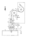
- FIG. 2 shows an exemplary embodiment of a doctor device arranged on the first cooling roller according to the invention. It has a replaceable squeegee bar 14 screwed onto the inside of the collecting container 9 (screws l3), which can be swiveled from the cooling roller 7 and adjusted against it by means of a swiveling device l6 actuated by an actuating cylinder l5. The contact pressure between the squeegee strip and the cooling roller can be adjusted on the spring l7 with the aid of the adjusting nut 25.
- a pull rod 28 is articulated on the swivel part 26.
- this pull rod By means of this pull rod, the squeegee strip is pressed against the cooling roller 7 by the spring 17 under an adjustable contact force.
- this spring is supported on an angle 29 fastened on the lever 20 and is placed at its other end against the adjusting nut 25.
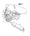
- FIG. 3 shows a traversing device for the doctor device shown in FIG. 2. (Compared to their positions shown in FIG. 2, the traversing axis 23, the lever 20, the pivoting part 26 and the pull rod 28 are shown in different angular positions in FIG. 3 for better clarity.)
- the length of the squeegee strip 14 is dimensioned such that when it is traversed, at least the jacket region of the cooling roll which is used by the paper web is coated in each of its positions. This length is then at least twice the traversing path greater than the width of the paper web.
- the traversing movement is accomplished by means of a traversing cylinder 3l which is clamped between a fork 32 clamped on the traversing axis and the bracket 2l.
- the traversing cylinder is actuated via valves and control lines (not shown), the stroke limitation being effected via limit switches 33 which are attached to the traversing axis and with interact with a stop 34 connected to the axis l9.
- the traversing axis 23 is mounted in a longitudinally displaceable manner in the tabs 2l by means of bearing bushes 35. (Only one of the two brackets arranged near the ends of the axes is shown.)
- the swivel part 26 is arranged so that it cannot move in the longitudinal direction of the traversing axis and is connected to one end of the pull rod 28 via an articulated rod head 36.
- the spring l7 pushed on at the other end of the pull rod is supported on the angle 29 by means of a spherical disk 37.
- the doctor bar 14 is provided in the contact area with the cooling roller 7 with a vulcanized-on elastomer casting resin. This allows a satisfactory service life of the squeegee to be achieved. If necessary, squeegee strips that are worn out can be replaced with new ones by their detachable screw connection to the collecting container. For appropriate service work as well as for cleaning the collecting container, the entire doctor device can be pivoted away from the cooling roller in the manner described above. The collecting container 9 can be removed from the machine after loosening the screws 27.
Landscapes
- Engineering & Computer Science (AREA)
- Mechanical Engineering (AREA)
- General Engineering & Computer Science (AREA)
- Textile Engineering (AREA)
- Supply, Installation And Extraction Of Printed Sheets Or Plates (AREA)
- Application Of Or Painting With Fluid Materials (AREA)
Abstract
In Rotationsdruckmaschinen durchläuft die Papierbahn (1) nach Verlassen der Druckwerke eine Einrichtung zur Nachbehandlung. Bekannte Einrichtungen bestehen aus einem beheizten Trockner (2), einem Dunstkanal (3) und einer Kühlwalzenanordnung (7) -in der genannten Reihenfolge-. Hierin werfen besonders die in Offsetdruckmaschinen verwendeten Druckfarben enthaltenen Lösungsmittel Probleme auf, da diese, bedingt durch die aus Kostengründen so kurz wie möglich gehaltene Baulänge der Maschinen, verstärkte Kondensatbildung an der Kühlwalzenanordnung mit sich bringen. Mit der erfindungsgemäßen Anordnung einer Rakelvorrichtung (8) wird eine Lösung aufgezeigt zum kontrollierten und umfeldschonenden Entzug von Lösungsmitteln aus dem Nachbehandlungsprozess. 
Description
Die Erfindung betrifft eine Einrichtung zur Nachbehandlung einer zumindest einseitig beschichteten oder bedruckten Gutbahn nach dem Oberbegriff des Anspruchs l.The invention relates to a device for the aftertreatment of an at least one-sided coated or printed material web according to the preamble of
Bei Druckmaschinen erfolgt eine Nachbehandlung solcher Gutbahnen mit dem Ziel, die Verflüchtigung der in Druckfarben enthaltenen Lösungsmittel so zu beschleunigen und die Druckfarben soweit zu trocknen, daß die Qualität des Druckbildes bei nachfolgenden Manipulationen mit der Gutbahn, beispielsweise in einem Falzapparat, erhalten bleibt.Post-treatment of such good webs is carried out with the aim of accelerating the volatilization of the solvents contained in printing inks and drying the printing inks to such an extent that the quality of the printed image is maintained during subsequent manipulations with the good web, for example in a folder.
Bei einer bekannten Einrichtung (DE-OS 33 05 749) durchläuft die Gutbahn zu diesem Zweck nach dem Bedrucken einen Trockner, in dem die Gutbahn aufgeheizt wird, und einen daran anschließenden Dunstkanal mit einer Blasdüsenanordnung, die im Dunstkanal eine der Durchlaufrichtung der Gutbahn entgegengesetzte Luftströmung erzeugt. Nach dem Verlassen des Dunstkanals wird die Gutbahn dann über eine Kühlwalzenanordnung geführt, durch deren Kühlwirkung die Druckfarbe verfestigt werden soll.In a known device (DE-OS 33 05 749), for this purpose, after printing, the gut web passes through a dryer in which the gut web is heated, and an adjoining vapor duct with a blower nozzle arrangement, which in the vapor duct has an air flow opposite the direction of passage of the gut web generated. After leaving the haze channel, the material web is then guided over a cooling roller arrangement, the cooling effect of which is intended to solidify the printing ink.
Mit der Anordnung eines solchermaßen mit Blasluft beaufschlagten Dunstkanals wird hierbei das Ziel verfolgt, die Konzentration des Lösungsmittels in der die Gutbahn umgebendenen Luft zu veringern, bevor die Gutbahn die Kühlwalzenanordnung erreicht, an der andernfalls größere Mengen an Lösungsmittel kondensieren würden.With the arrangement of a vapor channel so acted upon with blown air, the aim here is to reduce the concentration of the solvent in the air surrounding the material web before the material web reaches the cooling roller arrangement, on which larger amounts of solvent would otherwise condense.
Bei der bekannten Einrichtung ist weiterhin eine Blasvorrichtung vorgesehen, deren Luftstrom in der Nähe einer Kühlwalze auf die von der Kühlwalze abgewandte Oberfläche der Gutbahn und im wesentlichen in radialer Richtung zur Kühlwalze hin gerichtet ist.In the known device, a blowing device is also provided, the air flow of which, in the vicinity of a cooling roller, is directed toward the surface of the material web facing away from the cooling roller and essentially in the radial direction toward the cooling roller.
Damit soll ein inniger Kontakt zwischen Gutbahn und Kühlwalze erzwungen werden, um einen andernfalls hierzwischen auftretenden Luftspalt zu vermeiden, in den hinein noch vorhandenes Lösungsmittel verdampfen kann, und um ein schnelles Absinken der Gutbahntemperatur unter den Verdampfungspunkt des Lösungsmittels mit dem Ziel zu bewirken, daß die geringen noch anfallenden Kondensatmengen von der Gutbahn reabsorbiert werden und sich nicht auf der Kühlwalze ansammeln.This is intended to force an intimate contact between the material web and the chill roll, in order to avoid an air gap that would otherwise occur between them, into which solvent still present can evaporate, and to cause the material temperature to drop rapidly below the evaporation point of the solvent with the aim that the small amounts of condensate still to be reabsorbed by the gut web and do not accumulate on the chill roll.
Die Wirksamkeit all dieser Maßnahmen wird um so geringer, je höher die Bahngeschwindigkeit der Gutbahn wird. Insbesondere kann bei hohen Bahngeschwindigkeiten ein enger Kontakt der Gutbahn mit einer Kühlwalze nur mit erheblichem Blasdruck auf die Oberfläche der Gutbahn erreicht werden, wozu leistungsstarke Gebläse vorgesehen werden müssen.The higher the web speed of the Gutbahn, the lower the effectiveness of all these measures. In particular, at high web speeds, close contact of the material web with a cooling roller can only be achieved with considerable blowing pressure on the surface of the material web, for which purpose powerful blowers must be provided.
Der Erfindung liegt die Aufgabe zugrunde, eine Einrichtung der eingangs genannten Art zu schaffen, die insbesondere für hohe Gutbahngeschwindigkeiten geeignet ist.
Diese Aufgabe wird mit einer Einrichtung gemäß Anspruch l gelöst.The invention has for its object to provide a device of the type mentioned, which is particularly suitable for high web speeds.
This object is achieved with a device according to
Eine Rollenoffsetdruckmaschine kann mit einer erfindungsgemäß angeordneten Rakelvorrichtung auch bei starker Farb belegung mit Gutbahngeschwindigkeiten über 6,5 Meter pro Sekunde betrieben werden, ohne daß sich Lösungsmittelkondensate nachteilig auf die Druckqualität bemerkbar machen. Hierzu bedarf es insbesondere keiner Anstrengungen, wie sie in der genannten DE-OS 33 05 749 dargelegt sind, um den zwischen Gutbahn und Kühlwalze entstehenden Luftspalt zu verdrängen, in den hinein Lösungsmittel verdampfen kann.A web offset printing press can also be used with a doctor device arranged according to the invention even with strong ink occupancy with good web speeds over 6.5 meters per second, without solvent condensates having a negative impact on the print quality. For this purpose, in particular, no efforts are required, as set out in the aforementioned DE-OS 33 05 749, in order to displace the air gap which arises between the material web and the cooling roll and into which solvent can evaporate.
Erfindungsgemäß wird vielmehr der Weg beschritten, anstelle weiterer vorbeugender Maßnahmen gegen die Kondensatbildung auf der ersten Kühlwalze solche zur Vermeidung von deren nachteiligen Folgen zu ergreifen und dazu möglichst einfache Mittel einzusetzen.Rather, according to the invention, the path is taken instead of taking further preventive measures against the formation of condensate on the first cooling roll in order to avoid the disadvantageous consequences thereof and to use the simplest possible means for this purpose.
Damit erlangt auch das im Stand der Technik bislang nicht befriedigend gelöste Problem des Aufbrechens der mit der Gutbahn einhergehenden Grenzschicht aus Lösungsmitteldämpfe enthaltender Luft eine untergeordnete Bedeutung.Thus, the problem of breaking open the boundary layer of air containing solvent vapors associated with the material web, which has not yet been satisfactorily solved in the prior art, is of secondary importance.
Die Erfindung ist anschließend anhand von Zeichnungen eines Ausführungsbeispiels näher erläutert.
- Fig. l zeigt eine schematische Übersicht über eine erfindungsgemäß mit einem Kühlwalzenrakel ausgestattete Einrichtung zur Nachbehandlung einer beschichteten oder bedruckten Gutbahn.
- Fig. 2 zeigt ein Ausführungsbeispiel einer Rakelvorrichtung in einer Schwenklage mit an die Kühlwalze angestelltem Kühlwalzenrakel.
- Fig. 3 zeigt eine Traversiereinrichtung für die Rakelvorrichtung gemäß Fig. 2.
- 1 shows a schematic overview of a device according to the invention equipped with a cooling roll doctor for the aftertreatment of a coated or printed material web.
- 2 shows an exemplary embodiment of a doctor blade device in a swivel position with a cooling roller doctor blade applied to the cooling roller.
- FIG. 3 shows a traversing device for the doctor device according to FIG. 2.
In Fig. l ist eine Einrichtung zur Nachbehandlung einer beschichteten oder bedruckten Gutbahn schematisch dargestellt. Bei der Gutbahn l handelt es sich hierbei vorzugsweise um eine beidseitig bedruckte Papierbahn, welche die Druckwerke einer Rollenoffsetdruckmaschine durchlaufen hat. Die Papierbahn wird anschließend im Trockner 2 beheizt. Solche Trockner können an eine Absaugeinrichtung angeschlossen sein, mit der Lösungsmitteldämpfe abgesaugt werden, die aus der erhitzten Farbschicht der bedruckten Papierbahn austreten.A device for the aftertreatment of a coated or printed material web is shown schematically in FIG. The
Die Papierbahn tritt durch einen Schlitz in einer an den Dunstkanal 3 angrenzenden Wandung des Trockners in den Dunstkanal über. Um zu verhindern, daß größere Mengen von Lösungsmitteldampf durch diesen Schlitz aus dem Trockner austreten, sind Sperrdüsen 4 vorgesehen, aus denen Heißluft durch den Schlitz in den Trockner hineingeblasen wird.The paper web passes through a slot in a wall of the dryer adjoining the
Die heiß in den Dunstkanal eintretende Papierbahn gibt weiterhin Lösungsmittel ab, das zu einem Teil über die Dunstabsaugung 5 abgezogen werden kann. Ein anderer Teil wird mit der Papierbahn weitertransportiert, an der sich infolge Nachverdampfung von Lösungsmitel aus tieferen Farbschichten eine Grenzschicht aus lösungsmittelhaltiger Luft mit relativ hoher Lösungsmittelkonzentration ausbildet.The paper web entering the vapor duct when hot continues to emit solvent, some of which can be drawn off via the
Die Lösungsmittelkonzentration dieser Grenzschicht wird mit Hilfe von Blasdüsen 6 teilweise abgebaut, mit denen ein im wesentlichen entgegen der Durchlaufrichtung der Papierbahn gerichteter Blasluftstrom auf diese gerichtet wird.
Ein völliges "Aufbrechen" dieser Grenzschicht gelingt hiermit allerdings nicht, so daß die Papierbahn bei ihrem Auftreffen auf die erste Kühlwalze 7 noch mit Lösungsmitteldämpfen umgeben ist. Zwischen der diese Kühlwalze umschlingenden Oberfläche der Papierbahn und der Kühlwalzenmantelfläche bildet sich -verstärkt bei höheren Bahngeschwindigkeiten- ein Luftspalt aus. Dieser verschlechtert einerseits die Kühlwirkung auf die Papierbahn, so daß die Temperatur der Papierbahn im Bereich der ersten Kühlwalze noch wesentlich über dem Verdampfungspunkt des Lösungsmittels liegt; andererseits ermöglicht dieser Luftspalt, daß in diesen weiterhin Lösungsmitteldämpfe hineindiffundieren können, die sich dann an der kalten Oberfläche der ersten Kühlwalze als Kondensat niederschlagen.The solvent concentration of this boundary layer is partially reduced with the aid of blowing
A complete "breaking up" of this boundary layer does not succeed, however, so that the paper web is still surrounded by solvent vapors when it hits the
In der eingangs genannten DE-OS 33 05 749 wird über eine Anordnung berichtet, bei welcher Druckluft gegen diejenige Oberfläche einer Kühlwalze geblasen wird, die augenblicklich nicht von der Gutbahn umschlungen ist. Zweck dieser Maßnahme ist es offensichtlich, Lösungsmittelkondensate von der Kühlwalze zu verdrängen und zu verhindern, daß das auf dieser ausgefällte Lösungsmittel wieder in Berührung mit dem Bereich der Gutbahn kommt, der neu an die Kühlwalze herangeführt wird.In the aforementioned DE-OS 33 05 749 an arrangement is reported in which compressed air is blown against that surface of a cooling roll that is not currently wrapped in the web. The purpose of this measure is obviously to displace solvent condensates from the cooling roller and to prevent the solvent which has precipitated on it from coming into contact again with the region of the material web which is newly introduced to the cooling roller.
Dies ist auch ein Ziel der vorliegenden Erfindung. Die zitierte pneumatische Verdrängung benötigt einerseits ein leistungsstarkes Gebläse, was die Betriebskosten einer Druckmaschine nicht unwesentlich erhöht, und sie verursacht eine nicht tragbare Vernebelung der Druckmaschine und deren Umgebung mit Lösungsmitteln.
Mit der Erfindung wird jedoch eine Anordnung aufgezeigt, die eine Abgabe schädlicher Lösungsmitteldämpfe an die Maschine und insbesondere auch in die Maschinenhalle verhindert.This is also an object of the present invention. On the one hand, the cited pneumatic displacement requires a powerful blower, which increases the operating costs of a printing press not insignificantly, and it causes unsustainable atomization of the printing press and its Environment with solvents.
With the invention, however, an arrangement is shown which prevents the emission of harmful solvent vapors to the machine and in particular also into the machine hall.
Zur Lösung der obengenannten Aufgabe und zur Erzielung der genannten Vorteile bedient sich die Erfindung einer der ersten Kühlwalze zugeordneten Rakelvorrichtung, die auf ebenso verblüffend einfache wie wirkungsvolle Weise die Lösungsmittelkonzentration der der ersten Kühlwalze zugewandten Farbschicht bereits an dieser Kühlwalze merklich veringert.To achieve the above-mentioned object and to achieve the advantages mentioned, the invention makes use of a doctor device assigned to the first cooling roller, which, in an amazingly simple and effective manner, already markedly reduces the solvent concentration of the ink layer facing the first cooling roller on this cooling roller.
Mit der Rakelvorrichtung 8 (Fig. l) wird das an der ersten Kühlwalze 7 ausgefällte Lösungsmittelkondensat in einen Auffangbehälter 9 abgerakelt, aus dem es über einen Abflußstutzen l0 kontrolliert abgeführt werden kann.With the doctor device 8 (FIG. 1), the solvent condensate precipitated on the
Das abgerakelte Lösungsmittel geht dem weiteren Prozess insofern in wünschenswerter Weise verloren, als es andernfalls - ohne Abrakelung- von der drehenden Kühlwalze in den genannten Luftspalt zwischen dieser und der Papierbahn zurückbefördert würde. Dies hätte zur Folge, daß sich im genannten Luftspalt ein Kondensations-Diffusions-Gleichgewicht bei einer höheren Lösungsmittelkonzentration in der Farbschicht einstellen würde, was einem Nachverdampfen von Lösungsmitteln aus tieferen Farbschichten entgegenwirken würde. Das von der ersten Kühlwalze ablaufende Trum der Papierbahn hätte also ohne Abrakelung immer noch einen relativ hohen Lösungsmittelanteil in den tieferen Schichten der der Kühlwalze zugewandten Farbschicht. Dies wiederum hätte für die immer noch relativ heiße Papierbahn zur Folge, daß auf deren weiterem Weg eine nicht unerhebliche Nachdiffusion aus den tieferen Farbschichten erfolgen und dadurch die im Trockner bereits erhärtete Oberschicht der Farbe wieder erweichen würde. Bei Berührung einer solchermaßen wiedererweichten Farbschicht mit nachfolgenden Kühlwalzen würden hieran Farbablagerungen auftreten, die sich aus kleinsten Anfängen heraus gewissermaßen von einer "Keimzelle" ausgehend rasch aufbauen und das Druckbild verderben.The doctored solvent is desirably lost to the further process insofar as it would otherwise be conveyed back by the rotating cooling roller into the air gap between the latter and the paper web without being doctored. This would have the consequence that a condensation-diffusion equilibrium would occur in the air gap at a higher solvent concentration in the color layer, which would counteract the evaporation of solvents from deeper color layers. The run of the paper web running from the first cooling roller would therefore still have a relatively high proportion of solvent in the deeper layers of the ink layer facing the cooling roller without being doctored. This in turn would have been for the still relatively hot paper web Consequence that a not inconsiderable post-diffusion from the deeper layers of paint would take place on their further path and thereby soften the upper layer of the paint, which had already hardened in the dryer. If such a softened ink layer touched with subsequent cooling rollers, ink deposits would appear on it, which, starting from the smallest beginnings, quickly build up, as it were, from a "germ cell" and spoil the printed image.
Gemäß der Erfindung ist eine Rakelvorrichtung mit oben erläutertem Zweck nur an der ersten Kühlwalze vorgesehen. Im Hinblick auf die Investitionskosten für eine Druckmaschine muß unter anderem deren Gesamtlänge so kurz wie irgend möglich gehalten werden. Dies bedingt kurze Wege der Papierbahn vom Trockner bis zur ersten Kühlwalze und insbesondere bei größeren Papierbahngeschwindigkeiten äußerst kurze Zeitspannen, die der Farbe zum Abbau ihres Lösungsmittelgehaltes zur Verfügung stehen.
Auf der der ersten Kühlwalze 7 (Fig. l) abgewandten Seite der Papierbahn erfolgt die Abkühlung derselben und die Verdampfung einerseits ohne Wechselwirkung mit auf der ersten Kühlwalze niedergeschlagenem Lösungsmittelkondensat und andererseits über eine längere Zeitspanne bis zum Erreichen der zweiten Kühlwalze ll (Fig.l). Entsprechende Versuche haben gezeigt, daß an dieser zweiten Kühlwalze die Anordnung einer weiteren Rakelvorrichtung entbehrlich ist, und daß hier für qualitativ einwandfreie Druckergebnisse die bekannte Anordnung von Saugdüsen l2 (Fig. l) ausreichend ist, welche die Aufgabe haben, die von der Oberseite der Papierbahn an die Umgebung abgegebenen Lösungsmitteldämpfe abzusaugen.According to the invention, a doctor device with the purpose explained above is only provided on the first cooling roller. With regard to the investment costs for a printing machine, among other things, its total length must be kept as short as possible. This necessitates short paths of the paper web from the dryer to the first cooling roller and, especially at higher paper web speeds, extremely short periods of time which are available to the ink for reducing its solvent content.
On the side of the paper web facing away from the first cooling roller 7 (FIG. 1), cooling and evaporation take place on the one hand without interaction with solvent condensate deposited on the first cooling roller and on the other hand over a longer period of time until the second cooling roller 11 (FIG. 1) is reached. . Corresponding experiments have shown that the arrangement of a further doctor device is unnecessary on this second cooling roller, and that the known arrangement of suction nozzles l2 (FIG. 1), which have the task of being from the top of the paper web, is sufficient for qualitatively flawless printing results Aspirate solvent vapors released to the environment.
Fig. 2 zeigt ein Ausführungsbeispiel einer erfindungsgemäß an der ersten Kühlwalze angeordneten Rakelvorrichtung. Sie besitzt eine an die Innenseite des Auffangbehälters 9 angeschraubte (Schrauben l3) auswechselbare Rakelleiste l4, die über eine von einem Stellzylinder l5 betätigte Schwenkeinrichtung l6 von der Kühlwalze 7 abschwenkbar und gegen diese anstellbar ist. Die Anpreßkraft zwischen der Rakelleiste und der Kühlwalze ist an der Feder l7 mit Hilfe der Stellmutter 25 einstellbar.2 shows an exemplary embodiment of a doctor device arranged on the first cooling roller according to the invention. It has a
An nicht dargestellten Seitenwänden, in denen auch die Kühlwalze 7 gelagert ist, sind jeweils einander gegenüberliegende Lagerschilde l8 mittels Schrauben befestigt. In den Lagerschildern ist eine Achse l9 aufgenommen. Mit dieser Achse l9 sind ein Hebel 20 und eine Lasche 2l verstiftet. Der Hebel 20 wird durch den Stellzylinder l5 verschwenkt, der seinerseits um einen in einer Seitenwand befestigten Bolzen 22 verschwenkbar ist. Die mit der Achse l9 verstiftete Lasche 2l verschwenkt die Traversierachse 23 einer weiter unten anhand Figur 3 beschriebenen Traversiereinrichtung für die Rakelleiste l4. Der Auffangbehälter 9 ist über ein Verbindungsstück 24 an einem um die Traversierachse 23 schwenkbar gelagerten Schwenkteil 26 verschraubt (Schraube 27).On opposite side walls, in which the
Am Schwenkteil 26 ist eine Zugstange 28 angelenkt. Mittels dieser Zugstange wird die Rakelleiste durch die Feder l7 unter einstellbarer Anpreßkraft gegen die Kühlwalze 7 gedrückt. Hierzu ist diese Feder an einem auf dem Hebel 20 befestigten Winkel 29 abgestützt und an ihrem anderen Ende gegen die Stellmutter 25 angelegt.A
Die Rakelvorrichtung ist durch Vor- bzw. Rückhub des Stellzylinders anstellbar bzw. abschwenkbar. Im abgeschwenkten Zustand ist die Zugstange 28 mit einem Absatz 30 an dem Winkel 29 abgestützt.
Figur 3 zeigt eine Traversiereinrichtung für die in Figur 2 dargestellte Rakelvorrichtung. (Gegenüber ihren im Figur 2 dargestellten Lagen sind in Figur 3 der besseren Übersichtlichkeit wegen die Traversierachse 23, der Hebel 20, das Schwenkteil 26 und die Zugstange 28 in anderen Winkelstellungen dargestellt.)The squeegee device can be adjusted or swung out by the forward or return stroke of the actuating cylinder. In the swiveled-out state, the
FIG. 3 shows a traversing device for the doctor device shown in FIG. 2. (Compared to their positions shown in FIG. 2, the traversing
Die Länge der Rakelleiste l4 ist so bemessen, daß bei deren Traversierung in jeder ihrer Stellungen zumindest der von der Papierbahn beanspruchte Mantelbereich der Kühlwalze bestrichen wird. Diese Länge ist danach wenigstens um das Doppelte des Traversierweges größer als die Breite der Papierbahn.The length of the
Die Traversierbewegung wird mittels eines Traversierzylinders 3l bewerkstelligt, der zwischen einer auf die Traversierachse geklemmten Gabel 32 und der Lasche 2l eingespannt ist. (Die Gabel 32 ist in Figur 2 der besseren Übersichtlichkeit halber nicht in ihrer tatsächlichen Stellung bezüglich der Traversierachse dargestellt.) Der Traversierzylinder wird über nicht dargestellte Ventile und Steuerleitungen angesteuert, wobei die Hubbegrenzung über Endschalter 33 erfolgt, die an der Traversierachse angebracht sind und mit einem mit der Achse l9 verbundenen Anschlag 34 zusammenwirken.The traversing movement is accomplished by means of a traversing cylinder 3l which is clamped between a
Die Traversierachse 23 ist mittels Lagerbuchsen 35 in den Laschen 2l längsverschieblich gelagert. (Von den beiden jeweils nahe der Achsendenden angeordneten Laschen ist nur eine dargestellt.) Das Schwenkteil 26 ist in Längsrichtung der Traversierachse unverschieblich angeordnet und über einen Gelenkstangenkopf 36 mit einem Ende der Zugstange 28 verbunden. Die am anderen Ende der Zugstange aufgeschobene Feder l7 stützt sich an dem Winkel 29 über eine Kugelscheibe 37 ab.The traversing
In der in Figur 3 dargestellten Lage der Zugstange 28 schwenkt diese bei der Travesierung in der Auflage der Kugelscheibe 37 in der Zeichenebene hin und her. Die von der Zugstange durchgriffene Ausnehmung 38 des Winkels ist entsprechend des Ausschlags dieser Schwenkbewegung bemessen.In the position of the
Bei einer vorteilhaften Ausführungsform der Erfindung ist die Rakelleiste l4 im Kontaktbereich mit der Kühlwalze 7 mit einem aufvulkanisierten Elastomer-Gießharz versehen. Hiermit läßt sich eine befriedigende Lebensdauer der Rakelleiste erzielen. Gegebenenfalls abgenutzte Rakelleisten können durch deren lösbare Schraubverbindung mit dem Auffangbehälter durch neue ersetzt werden. Zu entsprechenden Servicearbeiten wie auch zum Reinigen des Auffangbehälters kann die gesamte Rakelvorrichtung auf die weiter oben beschriebene Weise von der Kühlwalze abgeschwenkt werden. Der Auffangbehälter 9 kann nach Lösen der Schrauben 27 aus der Maschine entnommen werden.In an advantageous embodiment of the invention, the
Claims (6)
dadurch gekennzeichnet,
daß eine Rakelvorrichtung (8) mit traversierendem Rakel an einem zwischen dem auflaufenden und dem ablaufenden Trum der Gutbahn (l) gelegenen Bereich der ersten Kühlwalze (7) vorgesehen ist.1.Device for the aftertreatment of an at least one-sided coated or printed material web, consisting essentially of a dryer heating the material web for the evaporation of solvents, an adjoining haze channel through which the material web passes, and a cooling roller arrangement arranged downstream of the air duct, the cooling rollers of which each cover a region of their Are encircled by the material web, and the first cooling roller of which is arranged in the direction of passage of the material web so that a coated or printed side of the material web and the surface of this cooling roller face each other,
characterized,
that a squeegee device (8) with a traversing squeegee is provided on an area of the first cooling roller (7) located between the running and the running run of the material web (1).
dadurch gekennzeichnet,
daß die Rakelvorrichtung einen abgerakeltes Lösungsmittelkondensat aufnehmenden Auffangbehälter (9) aufweist.2. Device according to claim l,
characterized,
that the doctor device has a scraped-off solvent condensate-collecting container (9).
dadurch gekennzeichnet,
daß der Auffangbehälter (9) einen Abflußstutzen (l0) zum Anschluß an eine Entsorgungseinrichtung für Lösungsmittelkondensat aufweist.3. Device according to claim 2,
characterized,
that the collecting container (9) has a drain connection (10) for connection to a disposal device for solvent condensate.
dadurch gekennzeichnet,
daß die Rakelvorrichtung eine auswechselbare Rakelleiste (l4) besitzt, auf die wenigstens im Kontaktbereich mit der Kühlwalze (7) ein Elastomer-Gießharz aufvulkanisiert ist.4. Device according to claim l,
characterized,
that the squeegee device has an exchangeable squeegee strip (14), onto which an elastomer casting resin is vulcanized at least in the contact area with the cooling roller (7).
dadurch gekennzeichnet,
daß die Rakelleiste wenigstens um das Doppelte des einfachen Verfahrweges der traversierenden Rakelvorrichtung länger ist als die Breite der Gutbahn.5. Device according to claim l,
characterized,
that the doctor bar is at least twice the simple travel of the traversing doctor device longer than the width of the gutter.
dadurch gekennzeichnet,
daß die Rakelvorrichtung mittels einer von einem Stellzylinder (l5) betätigten Schwenkeinrichtung (l6) von der Kühlwalze (7) abschwenkbar und gegen diese anstellbar ist, und daß die Schwenkeinrichtung eine die Anpreßkraft zwischen Rakelleiste und Kühlwalze bestimmende einstellbare Feder (l7) aufweist.6. Device according to claim l,
characterized,
that the squeegee device can be swiveled from the cooling roller (7) and adjusted against it by means of a swivel device (l6) actuated by an actuating cylinder (l5), and that the swivel device has an adjustable spring (l7) which determines the contact pressure between the squeegee bar and the cooling roll.
Applications Claiming Priority (2)
| Application Number | Priority Date | Filing Date | Title |
|---|---|---|---|
| DE3614742 | 1986-04-30 | ||
| DE19863614742 DE3614742A1 (en) | 1986-04-30 | 1986-04-30 | DEVICE FOR TREATING A COATED OR PRINTED RAILWAY |
Publications (3)
| Publication Number | Publication Date |
|---|---|
| EP0245634A2 true EP0245634A2 (en) | 1987-11-19 |
| EP0245634A3 EP0245634A3 (en) | 1988-07-20 |
| EP0245634B1 EP0245634B1 (en) | 1991-06-12 |
Family
ID=6299937
Family Applications (1)
| Application Number | Title | Priority Date | Filing Date |
|---|---|---|---|
| EP87104697A Expired - Lifetime EP0245634B1 (en) | 1986-04-30 | 1987-03-31 | Device for the aftertreatment of a coated or printed web |
Country Status (6)
| Country | Link |
|---|---|
| US (1) | US4852492A (en) |
| EP (1) | EP0245634B1 (en) |
| JP (1) | JPS62263052A (en) |
| CN (1) | CN1004543B (en) |
| CA (1) | CA1284028C (en) |
| DE (1) | DE3614742A1 (en) |
Cited By (1)
| Publication number | Priority date | Publication date | Assignee | Title |
|---|---|---|---|---|
| EP3702164A1 (en) * | 2019-03-01 | 2020-09-02 | Ricoh Company, Ltd. | Apparatus, inlet air unit and liquid discharging apparatus |
Families Citing this family (15)
| Publication number | Priority date | Publication date | Assignee | Title |
|---|---|---|---|---|
| DE3723400C1 (en) * | 1987-07-15 | 1989-02-23 | Baldwin Gegenheimer Gmbh | Method and device for cleaning cylinders of a web printing press |
| DE9116646U1 (en) * | 1991-06-07 | 1993-06-03 | Eltex-Elektrostatik GmbH, 7858 Weil | Device for increasing heat transfer to cooling rollers of offset web rotary machines |
| US5167189A (en) * | 1991-11-08 | 1992-12-01 | Jones Phillip W | Cylinder impurity remover apparatus |
| DE4325725C2 (en) * | 1993-07-30 | 1998-02-19 | Cleanpack Gmbh Innovative Verp | Method and device for winding film webs printed in roll offset printing |
| US5787809A (en) * | 1993-12-11 | 1998-08-04 | Eltex-Elektrostatik Gmbh | Printed web smoothing device and method |
| DE4409954A1 (en) * | 1994-03-23 | 1995-09-28 | Bse Printtechnologie | Rotary offset heat-set printer for lengths of product |
| EP0701958B1 (en) * | 1994-09-02 | 1998-07-15 | Heidelberger Druckmaschinen Aktiengesellschaft | Device for guiding a sheet |
| DE19615198C1 (en) * | 1996-04-17 | 1997-07-24 | Grafotec Gmbh | Rewetting freshly printed dried printed matter |
| ITMI20031131A1 (en) * | 2003-06-05 | 2004-12-06 | Omet Srl | METHOD AND DEVICE FOR CLEANING A CYLINDER OF |
| US20060096121A1 (en) * | 2004-11-05 | 2006-05-11 | Yugen Kaisha Advanced Engineering | Ink drying device of web offset press |
| DE102006027146B4 (en) * | 2006-06-12 | 2009-06-04 | Koenig & Bauer Aktiengesellschaft | A method for reducing the required cooling capacity in a cooling roll stand of a web-fed rotary printing press and a device in a cooling roll stand with cooling rolls |
| JP5745830B2 (en) * | 2010-12-06 | 2015-07-08 | 住友理工株式会社 | Method and apparatus for producing solid natural rubber |
| CN104908408B (en) * | 2015-06-08 | 2017-06-16 | 温州顺威包装有限公司 | A kind of four-color press |
| CN109028875A (en) * | 2018-07-25 | 2018-12-18 | 赣州市翔义科技有限公司 | A kind of cleaning plant of the garment material with drying dedusting function |
| CN114812140A (en) * | 2022-05-11 | 2022-07-29 | 徐亿强 | Weaving drying device with automatically function of carrying |
Family Cites Families (13)
| Publication number | Priority date | Publication date | Assignee | Title |
|---|---|---|---|---|
| US1772470A (en) * | 1928-07-13 | 1930-08-12 | William J Snyder | Ink-removing device |
| US1756841A (en) * | 1928-09-01 | 1930-04-29 | Ullring George | Roll wiper or cleaner for printing presses and similar machines |
| DE1042611B (en) * | 1943-03-27 | 1958-11-06 | Edmund Arthur Rogge | Swiveling squeegee of a gravure printing machine |
| US3065487A (en) * | 1960-11-21 | 1962-11-27 | Vickerys Ltd | Doctors for paper making machines |
| SE309902B (en) * | 1965-08-25 | 1969-04-08 | Svenska Flaektfabriken Ab | |
| US3656200A (en) * | 1969-11-14 | 1972-04-18 | Xerox Corp | Cleaning apparatus |
| BE795033A (en) * | 1972-02-09 | 1973-05-29 | Daetwyler & Co M | SQUEEGEE FOR HELIOGRAPHING MACHINES |
| FI53333C (en) * | 1972-11-13 | 1978-04-10 | Valmet Oy | TORKNINGSCYLINDERGRUPP I EN FLERCYLINDERTORK FOER EN MATERIALBANA I SYNNERHET FOER PAPPER |
| US3835779A (en) * | 1973-01-26 | 1974-09-17 | Pitney Bowes Inc | Apparatus for automatically cleaning the blanket cylinder of an offset printer |
| DE2716613C2 (en) * | 1977-04-15 | 1982-09-16 | Vits-Maschinenbau Gmbh, 4018 Langenfeld | Device for drying printed or coated webs of material |
| IT1117306B (en) * | 1977-06-27 | 1986-02-17 | Bugnone Aldo | TROLLEY FOR MACHINES FOR THE CONTINUOUS TREATMENT OF TAPE MATERIAL |
| US4462169A (en) * | 1982-02-19 | 1984-07-31 | W. R. Grace & Company | Web dryer solvent vapor control means |
| DE3328162C2 (en) * | 1983-08-04 | 1986-02-20 | J.M. Voith Gmbh, 7920 Heidenheim | Paper machine |
-
1986
- 1986-04-30 DE DE19863614742 patent/DE3614742A1/en active Granted
-
1987
- 1987-03-05 CA CA000531278A patent/CA1284028C/en not_active Expired - Lifetime
- 1987-03-31 EP EP87104697A patent/EP0245634B1/en not_active Expired - Lifetime
- 1987-04-30 JP JP62104873A patent/JPS62263052A/en active Pending
- 1987-04-30 CN CN87103696.7A patent/CN1004543B/en not_active Expired
-
1988
- 1988-11-14 US US07/273,132 patent/US4852492A/en not_active Expired - Lifetime
Cited By (2)
| Publication number | Priority date | Publication date | Assignee | Title |
|---|---|---|---|---|
| EP3702164A1 (en) * | 2019-03-01 | 2020-09-02 | Ricoh Company, Ltd. | Apparatus, inlet air unit and liquid discharging apparatus |
| US11235598B2 (en) | 2019-03-01 | 2022-02-01 | Ricoh Company, Ltd. | Apparatus, inlet air unit and liquid discharging apparatus |
Also Published As
| Publication number | Publication date |
|---|---|
| CN1004543B (en) | 1989-06-21 |
| DE3614742A1 (en) | 1987-11-05 |
| EP0245634B1 (en) | 1991-06-12 |
| JPS62263052A (en) | 1987-11-16 |
| US4852492A (en) | 1989-08-01 |
| EP0245634A3 (en) | 1988-07-20 |
| DE3614742C2 (en) | 1989-12-07 |
| CN87103696A (en) | 1987-11-11 |
| CA1284028C (en) | 1991-05-14 |
Similar Documents
| Publication | Publication Date | Title |
|---|---|---|
| EP0245634B1 (en) | Device for the aftertreatment of a coated or printed web | |
| EP0878301B1 (en) | Transport of sheets without offsetting in a rotary printing press | |
| DE3920730A1 (en) | DEVICE FOR ARC SMOOTHING ON THE PRINT CYLINDER IN AN ARC ROTATION PRINTING MACHINE | |
| DE19523076C2 (en) | Device for achieving a perfect support of a printing substrate in a printing press | |
| DE4429891A1 (en) | Multi-color web-fed rotary printing machine for commercial printing | |
| EP1046500B1 (en) | Cooling and remoistening unit for rotary presses | |
| DE4408027A1 (en) | Multi-color web-fed rotary printing machine for commercial printing | |
| DE60020651T2 (en) | Dual air curtain device for reducing the penetration of dampening solution into the inking unit of an offset printing machine | |
| EP2367636A2 (en) | Method and apparatus for the non-contact application of a uv print varnish onto a print substrate | |
| EP0788878A1 (en) | Method and means for guiding a web between two cylinders of a printing machine | |
| EP0000011B2 (en) | Rotary sheet printing machine. | |
| DE10102221A1 (en) | Device for slowing down signatures | |
| DE3536536A1 (en) | Air-blower drum as transfer drum and delivery drum in sheet-handling machines | |
| DE8204506U1 (en) | OFFSET ROTATION PRINTING MACHINE WITH A DEVICE FOR INTERRUPTING THE DAMPENER SUPPLY | |
| EP1059167A1 (en) | Inking device for a printing machine | |
| DE102008042620B4 (en) | Apparatus and method for removing dampening solution from an inking unit | |
| DE4332708C1 (en) | Device for conveying sheets without smearing in an offset printing machine | |
| EP1498264B1 (en) | Printer | |
| DE29914812U1 (en) | Printing unit for the reprint | |
| DE3906647A1 (en) | SHORT COLOR PLANT | |
| DE102013200113B4 (en) | Printing machine and a method for drying at least one printing substrate | |
| WO1999043501A1 (en) | Offset printing method and an offset printing machine | |
| DE4342203A1 (en) | Arc working=in device for arc=rotation printing press | |
| DE19926749A1 (en) | Ink mechanism for printer has ink transfer roller(s) subjected to air flow, forced delivery arrangement with hood for feeding air flow along roller surface on part of its circumference | |
| DE688935C (en) | printing machine for sheets |
Legal Events
| Date | Code | Title | Description |
|---|---|---|---|
| PUAI | Public reference made under article 153(3) epc to a published international application that has entered the european phase |
Free format text: ORIGINAL CODE: 0009012 |
|
| 17P | Request for examination filed |
Effective date: 19870331 |
|
| AK | Designated contracting states |
Kind code of ref document: A2 Designated state(s): CH DE FR GB IT LI NL SE |
|
| PUAL | Search report despatched |
Free format text: ORIGINAL CODE: 0009013 |
|
| RIN1 | Information on inventor provided before grant (corrected) |
Inventor name: BULCSU, ISTVAN Inventor name: PFIZENMAIER, WOLFGANG |
|
| AK | Designated contracting states |
Kind code of ref document: A3 Designated state(s): CH DE FR GB IT LI NL SE |
|
| RHK1 | Main classification (correction) |
Ipc: F26B 13/02 |
|
| 17Q | First examination report despatched |
Effective date: 19890915 |
|
| GRAA | (expected) grant |
Free format text: ORIGINAL CODE: 0009210 |
|
| AK | Designated contracting states |
Kind code of ref document: B1 Designated state(s): CH FR GB IT LI NL SE |
|
| GBT | Gb: translation of ep patent filed (gb section 77(6)(a)/1977) | ||
| ET | Fr: translation filed | ||
| ITF | It: translation for a ep patent filed | ||
| PGFP | Annual fee paid to national office [announced via postgrant information from national office to epo] |
Ref country code: SE Payment date: 19920316 Year of fee payment: 6 |
|
| PG25 | Lapsed in a contracting state [announced via postgrant information from national office to epo] |
Ref country code: LI Effective date: 19920331 Ref country code: CH Effective date: 19920331 |
|
| PGFP | Annual fee paid to national office [announced via postgrant information from national office to epo] |
Ref country code: NL Payment date: 19920331 Year of fee payment: 6 |
|
| PLBE | No opposition filed within time limit |
Free format text: ORIGINAL CODE: 0009261 |
|
| STAA | Information on the status of an ep patent application or granted ep patent |
Free format text: STATUS: NO OPPOSITION FILED WITHIN TIME LIMIT |
|
| 26N | No opposition filed | ||
| REG | Reference to a national code |
Ref country code: CH Ref legal event code: PL |
|
| PG25 | Lapsed in a contracting state [announced via postgrant information from national office to epo] |
Ref country code: SE Effective date: 19930401 |
|
| PG25 | Lapsed in a contracting state [announced via postgrant information from national office to epo] |
Ref country code: NL Effective date: 19931001 |
|
| NLV4 | Nl: lapsed or anulled due to non-payment of the annual fee | ||
| EUG | Se: european patent has lapsed |
Ref document number: 87104697.5 Effective date: 19931110 |
|
| PGFP | Annual fee paid to national office [announced via postgrant information from national office to epo] |
Ref country code: GB Payment date: 19990222 Year of fee payment: 13 |
|
| PG25 | Lapsed in a contracting state [announced via postgrant information from national office to epo] |
Ref country code: GB Free format text: LAPSE BECAUSE OF NON-PAYMENT OF DUE FEES Effective date: 20000331 |
|
| GBPC | Gb: european patent ceased through non-payment of renewal fee |
Effective date: 20000331 |
|
| PG25 | Lapsed in a contracting state [announced via postgrant information from national office to epo] |
Ref country code: IT Free format text: LAPSE BECAUSE OF NON-PAYMENT OF DUE FEES;WARNING: LAPSES OF ITALIAN PATENTS WITH EFFECTIVE DATE BEFORE 2007 MAY HAVE OCCURRED AT ANY TIME BEFORE 2007. THE CORRECT EFFECTIVE DATE MAY BE DIFFERENT FROM THE ONE RECORDED. Effective date: 20050331 |
|
| REG | Reference to a national code |
Ref country code: FR Ref legal event code: TP |
|
| PGFP | Annual fee paid to national office [announced via postgrant information from national office to epo] |
Ref country code: FR Payment date: 20060317 Year of fee payment: 20 |