EP0000011B2 - Rotary sheet printing machine. - Google Patents
Rotary sheet printing machine. Download PDFInfo
- Publication number
- EP0000011B2 EP0000011B2 EP78100018A EP78100018A EP0000011B2 EP 0000011 B2 EP0000011 B2 EP 0000011B2 EP 78100018 A EP78100018 A EP 78100018A EP 78100018 A EP78100018 A EP 78100018A EP 0000011 B2 EP0000011 B2 EP 0000011B2
- Authority
- EP
- European Patent Office
- Prior art keywords
- sheet
- drum
- guide plate
- sheet transfer
- printing
- Prior art date
- Legal status (The legal status is an assumption and is not a legal conclusion. Google has not performed a legal analysis and makes no representation as to the accuracy of the status listed.)
- Expired
Links
Images
Classifications
-
- B—PERFORMING OPERATIONS; TRANSPORTING
- B41—PRINTING; LINING MACHINES; TYPEWRITERS; STAMPS
- B41F—PRINTING MACHINES OR PRESSES
- B41F21/00—Devices for conveying sheets through printing apparatus or machines
- B41F21/10—Combinations of transfer drums and grippers
- B41F21/106—Combinations of transfer drums and grippers for reversing sheets, e.g. for perfecting machine
Definitions
- the invention relates to a sheet-fed rotary printing press for face and back printing with sheet transfer drums arranged between the printing units, under which stationary sheet-guiding plates extending over their entire width are provided.
- a device for sheet transfer and application in which hollow sheet guide bars with air outlet openings are arranged below the transfer point of the sheet between the printing cylinder and sheet transfer drum. Air is blown out of these air outlet openings with increased pressure in order to prevent the fine pressure on the sheet guiding bars from being smeared off.
- the DT-PS 21 28 216 discloses a device for sheet transfer and use in printing presses for optional face or reverse printing, in which a sheet transfer drum together with the upstream printing cylinder represent a sheet turning station. Both under the impression cylinder and under the sheet transfer drum, a sheet guide plate is provided stationary at a short distance from the drum or cylinder circumference, which are connected to one another via an adjustable third or middle sheet guide plate. The last-mentioned sheet guide plate can be converted into a face and a face and back printing position.
- all three sheet guide plates form a closed guide which, tangentially starting from the circumference of the impression cylinder, opens into an equidistant path running near the circumference of the sheet transfer drum.
- the middle sheet is used as a paddock; a thrust loop is pivoted into the gap between the printing cylinder and the sheet transfer drum, so that it extends tangentially to it at a short distance from the circumference of the sheet transfer drum.
- a disadvantage of the known device is that in the perfecting position because of the tangential. Guiding the sheet guide in the reversal of the movement of the sheet guided by the impression cylinder, so when it has been detected at its rear edge, because of its low speed at this time and its movement parallel to the sheet guide, it tends very easily to at least with its rear end on the Lay the sheet guide plate, whereby the printed underside of the sheet is smeared. But the face-to-face position of the middle sheet guide plate is also not without problems. Experiments have shown that the sheet end tends to stick to the cylinder circumference of the impression cylinder or to overtake the cylinder in the case of particularly smooth papers, which is why it slides over the upper edge of the middle sheet sheet employed.
- the second turning station is now, for example, in a five-color press with two turning stations between printing unit two and three, the underside of the sheet is printed on a four-color fine and single-color counterprint. Despite the fine printing position of the sheet guide plate, this printed underside of the sheet smears because it is pulled over the edge of the adjusted sheet guide plate.
- the object of the invention is to attach sheet guide plates under sheet transfer drums in such a stationary manner that the sheet is gently guided both in straight printing and in perfecting and smearing of a printed underside of the sheet does not occur.
- the invention consists in that the sheet guide plate of the sheet transfer drum upstream of a printing cylinder approaches the drum circumference in the direction of drum rotation and the sheet guide plate of the sheet transfer drum which is respectively arranged downstream of the printing cylinder moves away from the drum circumference in the direction of drum rotation, such that there is between the underside of the sheet transported by the respective sheet transfer drum and the associated guide plate inevitably forms an air cushion at every machine speed, the sheet transfer drum arranged directly in front of the printing cylinder being designed as a turning drum and the end of the sheet transfer plate, which is arranged upstream of the turning drum, runs almost radially to the turning drum, that is to say downwards, from the turning drum points.
- DE-B-2544566 and DE-B-25 52 998 have already made known sheet guiding plates for chain chain laying, which are intended to feed the sheet taken from the last printing unit to the delivery stack without smearing by forming an air cushion.
- the lower end of the sheet guide plate is guided tangentially past the take-up drum in the form of an extension. This measure cannot prevent the ends of stiffer sheets from spreading from the take-off drum and hitting the edge of the sheet guide plate before an air cushion forms. Lubrication of the printed sheet side cannot consequently be prevented with a sheet guide plate extending tangentially beyond the removal drum.
- the second-mentioned also referring to a sheet delivery DE-B-2552998 shows a sheet guide plate, which begins directly in the vicinity of the sheet transfer point between the last printing cylinder and the chain delivery and steadily, z. B. spirally, removed from the take-off drum.
- this measure promotes the formation of an air cushion on the sheet guide plate, because the trailing edge of the sheet lies against the spiral-shaped sheet guide plate end and thereby pushes an air cushion in front of it.
- An air cushion is only formed in cooperation with the baffle section under the chain arm.
- both curved guide plate guides in the known chain brackets do not give any indication as to how a curved guide plate is to be formed under a turning drum, namely pointing radially downward, in order to reliably prevent smearing.
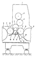
- a printing unit 1 of a multicolor printing machine which is located in the middle area, is shown, which can be converted from straight printing to face and back printing.
- the printing unit 1 consists, as usual, of a plate cylinder 2, a blanket cylinder 3 and a printing cylinder 4.
- the printing cylinder 4 is preceded by a sheet transfer drum 5 designed as a reversing drum and a sheet transfer drum 6 provided with a double diameter.
- a sheet transfer drum 7 with a diameter that corresponds to that of the printing cylinder 4.
- the sheet transfer drum 7 there is again a sheet transfer drum 6 with a double diameter.
- the sheet transfer drum5 is therefore only called turning drum in the following.
- Both sheet guide plates 10 and 10 are fastened to a crossbar 8 fixed to the housing and which extends below the printing cylinder 4. Both sheet guide plates 9 and 10 extend over the entire width of the sheet transfer drums.
- the sheet guide plate 9 is located under the turning drum 5 and the sheet guide plate 10 is located under the sheet transfer drum 7.
- the upper end 11 of the sheet guide plate 9 begins in the immediate vicinity of the printing cylinder 4, then runs parallel for a short distance at a short distance, i. H. Equidistant from the drum circumference 12 of the turning drum 5, it then moves away from the drum circumference 12 and practically opens into the lower end 13, which runs almost radially to the turning drum 5 and extends almost as far downward as the sheet transfer drum 6 with a double diameter .
- the sheet guide plate 9 has a slightly sinusoidally curved shape.
- the upper end 14 of the other sheet guide plate 10 also begins in the immediate vicinity of the printing cylinder 4. At this point, the sheet guide plate 10 is closest to the drum circumference 15 of the sheet transfer drum 7 and it spirally moves away from the drum circumference in the direction of rotation of the sheet transfer drum 7.
- the sheet transfer drum 7 has taken over the sheet from the impression cylinder 4 and transfers it to the sheet transfer drum 6 with a double diameter.
- the rear end of the sheet is pressed so firmly onto the outer surface of the printing cylinder 4 that the sheet must be removed from the printing cylinder 4 and therefore clings closely to the drum circumference 15 of the sheet transfer drum 7.
- the non-printed trailing edge of the sheet lies on the sheet guide plate 10 and pushes an air cushion in front of it, which prevents the printed surface of the underside of the sheet from coming into contact with the guide surface of the sheet guide plate 10.
- smearing of the printed underside of the sheet is effectively prevented.
Landscapes
- Supply, Installation And Extraction Of Printed Sheets Or Plates (AREA)
- Feeding Of Articles By Means Other Than Belts Or Rollers (AREA)
Description
Die Erfindung betrifft eine Bogenrotationsdruckmaschine für Schön- und Widerdruck mit zwischen den Druckwerken angeordneten Bogenübergabetrommeln, unter denen sich über deren ganze Breite erstreckende stationär befestigte Bogenleitbleche vorgesehen sind.The invention relates to a sheet-fed rotary printing press for face and back printing with sheet transfer drums arranged between the printing units, under which stationary sheet-guiding plates extending over their entire width are provided.
Allgemein ist bekannt, unter Bogenübergabetrommeln von Bogenrotationsdruckmaschinen Leitbügel vorzusehen. Diese Maßnahme hat den Nachteil, daß bei Formatänderungen der zu bedruckenden Bogen des öfteren eine Verstellung der Leitbügel erforderlich wird, weil sich andernfalls im bedruckten Bogen Falten ausbilden.It is generally known to provide guide brackets under sheet transfer drums of sheet-fed rotary printing machines. This measure has the disadvantage that when the format of the sheet to be printed is changed, an adjustment of the guide bracket is often necessary, because otherwise wrinkles form in the printed sheet.
Aus der DL-PS 57 345 ist ferner eine Vorrichtung zur Bogenübergabe und -wendung bekannt, bei der unterhalb des Übergabepunktes des Bogens zwischen Druckzylinder und Bogenübergabetrommel hohle Bogenleitbügel mit Luftaustrittsöffnungen angeordnet sind. Aus diesen Luftaustrittsöffnungen wird Luft mit erhöhtem Druck ausgeblasen, um ein Abschmieren des Schöndruckes auf den Bogenleitbügeln zu verhindern.From DL-PS 57 345 a device for sheet transfer and application is also known, in which hollow sheet guide bars with air outlet openings are arranged below the transfer point of the sheet between the printing cylinder and sheet transfer drum. Air is blown out of these air outlet openings with increased pressure in order to prevent the fine pressure on the sheet guiding bars from being smeared off.
Bei dieser bekannten Ausführung kann sich jedoch über die gesamte Breite des geführten Bogens kein einheitliches Luftkissen ausbilden. Dünne Bogen werden von der austretenden Luft ':":"'g geblasen. Ihre Stabilität nimmt dadurch in Längsrichtung zu. Sie schmiegen sich daher widerstrebend an den Mantel des Bogenführungszylinders an. Da überdies die ausgeblasene Luft im Bereich der Bogenleitbügel nach allen Seiten ausweichen kann, lassen sich schwere Bogen kaum am Durchschlagen auf die Bogenleitbügel hindern. Die verhältnismäßig aufwendigen, mit Blasluft arbeitenden Bogenleitbügel können somit ein Verschmieren des Schöndrucks sowohl bei dünnen als auch bei dicken Bogen mit Sicherheit nicht verhindern.In this known embodiment, however, no uniform air cushion can form over the entire width of the guided sheet. Thin sheets are blown out of the emerging air ': ":"' g. This increases their stability in the longitudinal direction. They reluctantly nestle against the jacket of the sheet guide cylinder. In addition, since the blown-out air in the area of the sheet guide bars can deflect on all sides, heavy sheets can hardly be prevented from striking the sheet guide bars. The relatively complex sheet guiding brackets, which work with blown air, cannot therefore reliably prevent smearing of the face pressure, both with thin and with thick sheets.
Des weiteren ist durch die DT-PS 21 28 216 eine Vorrichtung zur Bogenübergabe und -wendung in Druckmaschinen für wahlweise Schön- oder Schön- und Widerdruck bekannt, bei der eine Bogenübergabetrommel zusammen mit dem vorgeschalteten Druckzylinder eine Bogenwendestation darstellen. Sowohl unter dem Druckzylinder als auch unter der Bogenübergabetrommel sind je ein Bogenleitblech in geringem Abstand vom Trommel- bzw. Zylinderumfang stationär vorgesehen, die über ein verstellbares drittes bzw. mittleres Bogenleitblech miteinander verbunden sind. Das letztgenannte Bogenleitblech ist in eine Schöndruck- und eine Schön- und Widerdruckstellung umstellbar.Furthermore, the DT-PS 21 28 216 discloses a device for sheet transfer and use in printing presses for optional face or reverse printing, in which a sheet transfer drum together with the upstream printing cylinder represent a sheet turning station. Both under the impression cylinder and under the sheet transfer drum, a sheet guide plate is provided stationary at a short distance from the drum or cylinder circumference, which are connected to one another via an adjustable third or middle sheet guide plate. The last-mentioned sheet guide plate can be converted into a face and a face and back printing position.
In der Schön- und Widerdruckstellung bilden alle drei Bogenleitbleche eine geschlossene Führung, die in geringem Abstand tangential vom Druckzylinderumfang ausgehend in eine nahe des Umfangs der Bogenübergabetrommel verlaufende äquidistante Bahn einmündet. Bei Schöndruck wird das mittlere Bogenblech als Koppel ; einer Schubschleife in den Spalt zwischen Druckzylinder und Bogenübergabetrommel geschwenkt, so daß es sich im geringen Abstand vom Umfang der Bogenübergabetrommel tangential dazu erstreckt.In the perfecting position, all three sheet guide plates form a closed guide which, tangentially starting from the circumference of the impression cylinder, opens into an equidistant path running near the circumference of the sheet transfer drum. In straight printing, the middle sheet is used as a paddock; a thrust loop is pivoted into the gap between the printing cylinder and the sheet transfer drum, so that it extends tangentially to it at a short distance from the circumference of the sheet transfer drum.
Von Nachteil ist bei der bekannten Vorrichtung, daß in der Schön- und Widerdruckstellung wegen der tangentialen. Führung der Bogenleitbahn in der Bewegungsumkehr des vom Druckzylinder geführten Bogens, dann also, wenn dieser an seiner Hinterkante erfaßt worden ist, wegen seiner zu diesem Zeitpunkt geringen Geschwindigkeit und seiner Bewegung parallel zur Bogenleitbahn sehr leicht dazu neigt, sich zumindest mit seinem hinteren Ende auf das Bogenleitblech abzulegen, wodurch die bedruckte Bogenunterseite verschmiert wird. Aber auch die Schöndruckstellung des mittleren Bogenleitblechs ist nicht unproblematisch. Versuche haben nämlich ergeben, daß das Bogenende dazu neigt, am Zylinderumfang des Druckzylinders haften zu bleiben oder bei besonders glatten Papieren den Zylinder zu überholen, weshalb es über die obere Kante des angestellten mittleren Bogenblechs hinweggleitet. Befindet sich nun die zweite Wendestation beispielsweise in einer Fünffarbenmaschine mit zwei Wendestationen zwischen Druckwerk zwei und drei, so ist bei einem Vierfarbenschön- und Einfarbenwiderdruck die Bogenunterseite bedruckt. Trotz der Schöndruckstellung des Bogenleitblechs verschmiert diese bedruckte Bogenunterseite, weil sie über die Kante des verstellten Bogenleitblechs hinweggezogen wird.A disadvantage of the known device is that in the perfecting position because of the tangential. Guiding the sheet guide in the reversal of the movement of the sheet guided by the impression cylinder, so when it has been detected at its rear edge, because of its low speed at this time and its movement parallel to the sheet guide, it tends very easily to at least with its rear end on the Lay the sheet guide plate, whereby the printed underside of the sheet is smeared. But the face-to-face position of the middle sheet guide plate is also not without problems. Experiments have shown that the sheet end tends to stick to the cylinder circumference of the impression cylinder or to overtake the cylinder in the case of particularly smooth papers, which is why it slides over the upper edge of the middle sheet sheet employed. If the second turning station is now, for example, in a five-color press with two turning stations between printing unit two and three, the underside of the sheet is printed on a four-color fine and single-color counterprint. Despite the fine printing position of the sheet guide plate, this printed underside of the sheet smears because it is pulled over the edge of the adjusted sheet guide plate.
Aufgabe der Erfindung ist es, Bogenleitbleche unter Bogenübergabetrommeln derart stationär anzubringen, daß sowohl bei Schöndruck als auch bei Schön- und Widerdruck der Bogen schonend geführt wird und ein Verschmieren einer bedruckten Bogenunterseite nicht auftritt.The object of the invention is to attach sheet guide plates under sheet transfer drums in such a stationary manner that the sheet is gently guided both in straight printing and in perfecting and smearing of a printed underside of the sheet does not occur.
Die Erfindung besteht darin, daß sich das Bogenleitblech der einem Druckzylinder vorgelagerten Bogenübergabetrommel in Trommeldrehrichtung dem Trommelumfang nähert und sich das Bogenleitblech der dem Druckzylinder jeweils nachgeordneten Bogenübergabetrommel in Trommeldrehrichtung von dem Trommelumfang entfernt, derart, daß sich zwischen der Unterseite des von der jeweiligen Bogenübergabetrommel transportierten Bogens und dem zugehörigen Leitblech bei jeder Maschinengeschwindigkeit zwangsläufig ein Luftkissen ausbildet, wobei die unmittelbar vor dem Druckzylinder angeordnete Bogenübergabetrommel als Wendetrommel ausgeführt ist und das einer der Wendetrommel vorgeschalteten Bogenübergabetrommel zugewandte Ende des über seine Länge sinusförmig ausgebildeten Bogenleitblechs nahezu radial zur Wendetrommel verläuft, also von dieser abwärts weist.The invention consists in that the sheet guide plate of the sheet transfer drum upstream of a printing cylinder approaches the drum circumference in the direction of drum rotation and the sheet guide plate of the sheet transfer drum which is respectively arranged downstream of the printing cylinder moves away from the drum circumference in the direction of drum rotation, such that there is between the underside of the sheet transported by the respective sheet transfer drum and the associated guide plate inevitably forms an air cushion at every machine speed, the sheet transfer drum arranged directly in front of the printing cylinder being designed as a turning drum and the end of the sheet transfer plate, which is arranged upstream of the turning drum, runs almost radially to the turning drum, that is to say downwards, from the turning drum points.
Ein Verstellen der Bogenführung bei Format- änderung oder bei Umstellung von Schön- auf Schön- und Widerdruck erübrigt sich. Das aufgrund einer Keilwirkung mit Sicherheit entstehende Luftkissen verhindert bei jeder Druckart, ob Schön-, ob Schön- und Widerdruck, bei jeder Papierstärke und auch bei jeder Druckleistung der Bogenrotationsdruckmaschine ein Auftreffen der bedruckten Bogenunterseite auf das Bogenleitblech. Ein Verschmieren von beidseitig bedruckten Bogen während des Bogentransports von Druckwerk zu Druckwerk tritt nicht mehr auf.There is no need to adjust the sheet guide when changing the format or changing from face to face. That on Air cushions created with certainty due to a wedge effect prevent the printed underside of the sheet from hitting the sheet guide plate with any type of print, whether it be perfect, whether it is perfect or reverse printing, with any paper thickness and also with each printing performance of the sheet-fed rotary printing press. Smearing of sheets printed on both sides during sheet transport from printing unit to printing unit no longer occurs.
Durch die DE-B-2544566 und die DE-B-25 52 998 sind bereits Bogenführungsbleche bei Kettenbogenauslegen bekannt geworden, die durch Bildung eines Luftkissens den vom letzten Druckwerk übernommenen Bogen abschmierfrei dem Auslagestapel zuführen sollen. Im erstgenannten Falle ist das untere Ende des Bogenleitblechs in Form einer Verlängerung tangential an der Abnahmetrommel vorbeigeführt. Diese Maßnahme kann nicht verhindern, daß sich die Enden steiferer Bögen von der Abnahmetrommel abspreizen und auf die Kante des Bogenleitblechs aufschlagen, bevor sich ein Luftkissen ausbildet. Ein Abschmieren der bedruckten Bogenseite läßt sich folglich mit einem sich tangential über die Abnahmetrommel hinauserstreckenden Bogenleitblech nicht verhindern.DE-B-2544566 and DE-B-25 52 998 have already made known sheet guiding plates for chain chain laying, which are intended to feed the sheet taken from the last printing unit to the delivery stack without smearing by forming an air cushion. In the former case, the lower end of the sheet guide plate is guided tangentially past the take-up drum in the form of an extension. This measure cannot prevent the ends of stiffer sheets from spreading from the take-off drum and hitting the edge of the sheet guide plate before an air cushion forms. Lubrication of the printed sheet side cannot consequently be prevented with a sheet guide plate extending tangentially beyond the removal drum.
Die an zweiter Stelle genannte, sich ebenfalls auf einen Bogenausleger beziehende DE-B-2552998 zeigt ein Bogenleitblech, das unmittelbar in der Nähe der Bogenübergabestelle zwischen dem letzten Druckzylinder und dem Kettenausleger beginnt und sich stetig, z. B. spiralförmig, von der Abnahmetrommel entfernt. Diese Maßnahme fördert zwar die Bildung eines Luftkissens auf dem Bogenleitblech, weil die Bogenhinterkante an dem spiralförmigen Bogenleitblechende anliegt und dadurch ein Luftpolster vor sich herschiebt. Zur Ausbildung eines Luftkissens kommt es aber nur im Zusammenwirken mit dem Leitblechabschnitt unter dem Kettenausleger. Beide Bogenleitblechführungen in den bekannten Kettenauslegern geben jedoch keinen Hinweis, wie ein Bogenleitblech unter einer Wendetrommel auszubilden sei, nämlich radial abwärts weisend, um mit Sicherheit ein Abschmieren zu verhindern.The second-mentioned, also referring to a sheet delivery DE-B-2552998 shows a sheet guide plate, which begins directly in the vicinity of the sheet transfer point between the last printing cylinder and the chain delivery and steadily, z. B. spirally, removed from the take-off drum. Although this measure promotes the formation of an air cushion on the sheet guide plate, because the trailing edge of the sheet lies against the spiral-shaped sheet guide plate end and thereby pushes an air cushion in front of it. An air cushion is only formed in cooperation with the baffle section under the chain arm. However, both curved guide plate guides in the known chain brackets do not give any indication as to how a curved guide plate is to be formed under a turning drum, namely pointing radially downward, in order to reliably prevent smearing.
Die Erfindung wird im folgenden durch ein Ausführungsbeispiel anhand der Zeichnung erläutert.The invention is explained below by an embodiment with reference to the drawing.
In der Figur ist ein im mittleren Bereich liegendes Druckwerk 1 einer Mehrfarbendruckmaschine dargestellt, die von Schöndruck auf Schön- und Widerdruck umstellbar ist. Das Druckwerk 1 besteht, wie üblich aus einem Plattenzylinder 2, einem Gummizylinder 3 und einem Druckzylinder 4. Dem Druckzylinder 4 ist eine als Wendetrommel ausgebildete Bogenübergabetrommel 5 und eine mit doppeltem Durchmesser versehene Bogenübergabetrommel 6.vorgelagert. Unmittelbar auf den Druckzylinder 4 folgt eine Bogenübergabetrommei 7 mit einem Durchmesser, der dem des Druckzylinders 4 entspricht. Anschließend an die Bogenübergabetrommel 7 folgt dann wieder eine Bogenübergabetrommel 6 mit doppeltem Durchmesser. Zwischen den Druckwerken befinden sich somit also drei Bogenübergabetrommeln 5, 6 und 7, wobei die Bogenübergabetrommel5 dann als Wendetrommel ausgebildet ist, wenn es sich um eine Wendestation handelt, was im vorliegenden Beispiel der Fall ist. Die Bogenübergabetrommel5 wird im folgenden daher nur noch Wendetrommel genannt.In the figure, a printing unit 1 of a multicolor printing machine, which is located in the middle area, is shown, which can be converted from straight printing to face and back printing. The printing unit 1 consists, as usual, of a plate cylinder 2, a
An einer gehäusefesten Quertraverse 8, die sich unterhalb des Druckzylinders 4 erstreckt, sind zwei Bogenleitbleche und 10 befestigt. Beide Bogenleitbleche 9 und 10 erstrecken sich über die gesamte Breite der Bogenübergabetrommeln. Das Bogenleitblech 9 befindet sich unter der Wendetrommel 5 und das Bogenleitblech 10 unter der Bogenübergabetrommel 7.Two
Das obere Ende 11 des Bogenleitblechs 9 beginnt in unmittelbarer Nähe des Druckzylinders 4, läuft dann in einem geringen Abstand eine kurze Strecke parallel, d. h. äquidistant, zum Trommelumfang 12 der Wendetrommel 5, entfernt sich danach von dem Trommelumfang 12 und mündet praktisch in das untere Ende 13 ein, das nahezu radial zur Wendetrommel 5 verläuft und sich dabei fast so weit abwärts erstreckt, wie die Bogen- überführungstrommel6 mit doppeltem Durchmesser. Das Bogenleitblech 9 hat dadurch eine schwach sinusförmig gekrümmte Form.The
Das obere Ende 14 des anderen Bogenleitblechs 10 beginnt ebenfalls in unmittelbarer Nähe des Druckzylinders 4. An dieser Stelle hat das Bogenleitblech 10 seine größte Nähe zum Trommelumfang 15 der Bogenübergabetrommel 7 und es entfernt sich in Drehrichtung der Bogenübergabetrommel 7 spiralförmig von deren Trommelumfang.The
Die Wirkungsweise der beiden Bogenleitbleche 9 und 10 ist unterschiedlich. Wenn bei Schöndruckstellung der aus Wendetrommel 5 und Bogenübergabetrommel 6 bestehenden Wendeeinrichtung das Ende des von der Wendetrommel geführten Bogens aus dem Spalt zwischen der Wendetrommel5 und der Bogenübergabetrommel 6 herausrutscht, bildet es beim Abwärtsfallen einen Luftkeil mit der Fläche des Bogenleitblechs 9. Dieser Luftkeil verdichtet sich zu einem sicher tragenden Luftkissen, sobald das Bogenende in den Bereich hineingezogen wird, in dem das obere Ende 11 des Bogenleitblechs 9 praktisch äquidistant zum Trommelumfar 12 der Wendetrommel 5 verläuft. Ein Auftreffen der möglicherweise bedruckten Unterseite auf die Führungsfläche des Bogenleitblechs 9 findet nicht statt.The operation of the two
Ähnlich verhält es sich bei der Schön- und Widerdruckstellung dieser Wendestation. Führt die Wendetrommel5 einen an seiner Hinterkante erfaßten Bogen 16, so wird das vordere Bogenende praktisch tangential von der Bogenübergabetrommei 6 abgezogen. Dabei bildet der Bogen 16 zwangsläufig zusammen mit dem sich nahezu senkrecht abwärts erstreckenden Ende 13 des Bogenleitblechs 9 einen recht beträchtlichen Luftkeil 17. Auch dieser Luftkeil 17 erzeugt ein derart starkes Luftkissen, daß selbst bei niedriger Druckleistung kein Verschmieren der bedruckten Bogenunterseite mittels der Führungsfläche des Bogenleitblechs 9 auftreten kann.The situation is similar for the perfecting and reverse printing of this turning station. If the turning
Anders verhält es sich mit dem Bogenleitblech 10. Die BogenübergabetrornmeI7 hat vom Druckzylinder 4 den Bogen übernommen und übergibt ihn an die Bogenübergabetrommel 6 mit doppeltem Durchmesser. Dabei ist infolge der Druckpressung das hintere Bogenende so fest auf die Mantelfläche des Druckzylinders 4 gepreßt, daß der Bogen vom Druckzylinder4 abgezogen werden muß und sich daher eng an den Trommelumfang 15 der Bogenübergabetrommel 7 anschmiegt. Erst wenn das hintere Ende des Bogens vom Druckzylinder4 abgezogen ist, fällt der Bogen herunter. Dabei legt sich die nichtbedruckte Bogenhinterkante auf das Bogenleitblech 10 und schiebt ein Luftkissen vor sich her, das verhindert, daß die bedruckte Fläche der Bogenunterseite mit der Führungsfläche des Bogenleitblechs 10 in Berührung kommt. Auch hier wird somit ein Verschmieren der bedruckten Bogenunterseite wirksam verhindert.It is different with the
Claims (2)
Applications Claiming Priority (2)
| Application Number | Priority Date | Filing Date | Title |
|---|---|---|---|
| DE2724856A DE2724856C3 (en) | 1977-06-02 | 1977-06-02 | Sheet-fed rotary printing press |
| DE2724856 | 1977-06-02 |
Publications (3)
| Publication Number | Publication Date |
|---|---|
| EP0000011A1 EP0000011A1 (en) | 1978-12-20 |
| EP0000011B1 EP0000011B1 (en) | 1980-04-30 |
| EP0000011B2 true EP0000011B2 (en) | 1983-08-24 |
Family
ID=6010493
Family Applications (1)
| Application Number | Title | Priority Date | Filing Date |
|---|---|---|---|
| EP78100018A Expired EP0000011B2 (en) | 1977-06-02 | 1978-06-01 | Rotary sheet printing machine. |
Country Status (12)
| Country | Link |
|---|---|
| US (1) | US4203361A (en) |
| EP (1) | EP0000011B2 (en) |
| JP (1) | JPS542807A (en) |
| AT (1) | AT362402B (en) |
| AU (1) | AU514401B2 (en) |
| BR (1) | BR7803516A (en) |
| CA (1) | CA1092437A (en) |
| DE (1) | DE2724856C3 (en) |
| ES (1) | ES470290A1 (en) |
| GB (1) | GB1577508A (en) |
| IT (1) | IT1108372B (en) |
| ZA (1) | ZA781172B (en) |
Families Citing this family (12)
| Publication number | Priority date | Publication date | Assignee | Title |
|---|---|---|---|---|
| JPS5722908Y2 (en) * | 1979-09-06 | 1982-05-18 | ||
| DE3228140A1 (en) * | 1982-07-28 | 1984-02-09 | M.A.N. Maschinenfabrik Augsburg-Nürnberg AG, 4200 Oberhausen | Line and line-connecting system for supplying pressure medium to machines |
| DE3411029A1 (en) * | 1984-03-24 | 1985-10-03 | M.A.N.- Roland Druckmaschinen AG, 6050 Offenbach | DEVICE FOR GUIDING SHEETS PRINTED ON SIDE AND BOTH SIDES |
| DE3602084A1 (en) * | 1986-01-24 | 1987-07-30 | Heidelberger Druckmasch Ag | BOW TRANSFER DRUM BETWEEN THE PRINTING UNITS OF ROTATIONAL PRINTING MACHINES |
| DE3710257A1 (en) * | 1987-03-28 | 1988-10-13 | Heidelberger Druckmasch Ag | BOW ROTATION PRINTING MACHINE FOR THE PRODUCTION OF SINGLE-SIDED MULTICOLOR PRINTING OR BEAUTIFUL AND REPRINTING |
| DE3830070A1 (en) * | 1988-09-03 | 1990-03-15 | Roland Man Druckmasch | MECHANICAL BOW GUIDE DEVICE IN BOWING MACHINE ON PRINTING MACHINES |
| DE9416106U1 (en) * | 1994-10-06 | 1994-11-24 | Heidelberger Druckmaschinen Ag, 69115 Heidelberg | Sheet guide plate for a turning device |
| DE19514252C1 (en) * | 1995-04-15 | 1996-08-22 | Heidelberger Druckmasch Ag | Offset rotary printing machine |
| KR20020055612A (en) * | 2000-12-29 | 2002-07-10 | 김형국 | Automatically Loaded Exparnder for steam generator |
| DE10357439B4 (en) * | 2003-12-09 | 2014-07-31 | manroland sheetfed GmbH | Substrate guiding device in a processing machine |
| DE102015209688B4 (en) | 2014-06-18 | 2020-06-10 | Koenig & Bauer Ag | Sheet turning device and method for turning sheets with a turning device |
| CN108024939B (en) | 2015-08-20 | 2024-06-07 | 联合利华知识产权控股有限公司 | Encapsulated lactams |
Family Cites Families (12)
| Publication number | Priority date | Publication date | Assignee | Title |
|---|---|---|---|---|
| DE555814C (en) * | 1928-11-11 | 1932-07-29 | Hamburger Fremdenblatt Brosche | Multi-color rotary printing machine for sheets |
| FR883712A (en) * | 1942-07-01 | 1943-07-13 | Method of drying printed surfaces, especially in multi-color intaglio printing machines, and multi-color intaglio printing machines | |
| US2610850A (en) * | 1948-02-24 | 1952-09-16 | Huck Co | Sheet delivery mechanism for printing machines |
| DE1102767B (en) * | 1958-08-21 | 1961-03-23 | Miehle Goss Dexter Inc | Sheet transport device on printing presses |
| US2933039A (en) * | 1958-08-21 | 1960-04-19 | Miehle Goss Dexter Inc | Sheet transferring mechanism |
| DE1561101A1 (en) * | 1966-12-27 | 1970-01-08 | Planeta Veb Druckmasch Werke | Sheet guide device for sheet guide cylinder |
| DE2128216C3 (en) * | 1970-07-20 | 1976-09-30 | Polygraph Leipzig | Device for sheet transfer and turning in printing machines for either face or face and reverse printing |
| US3742847A (en) * | 1970-11-27 | 1973-07-03 | Polygraph Leipzig Kom Veb | Sheet turning mechanism for perfectors |
| DE2137115A1 (en) * | 1971-07-24 | 1973-02-01 | Maschf Augsburg Nuernberg Ag | BOW CONVEYOR |
| DE2544566C3 (en) * | 1975-10-04 | 1984-11-15 | Miller Printing Equipment Corp., Pittsburgh, Pa. | Sheet delivery for sheet-fed printing machines |
| DE2552998C2 (en) * | 1975-11-26 | 1983-11-10 | Heidelberger Druckmaschinen Ag, 6900 Heidelberg | Sheet delivery for rotary printing machines |
| US4099463A (en) * | 1977-04-13 | 1978-07-11 | Veb Polygraph Leipzig Kombinat Fuer Polygraphische Maschinen Und Ausruestungen | Support arrangement for guiding sheets through a printing machine |
-
1977
- 1977-06-02 DE DE2724856A patent/DE2724856C3/en not_active Expired
-
1978
- 1978-02-28 ZA ZA00781172A patent/ZA781172B/en unknown
- 1978-03-14 AU AU34096/78A patent/AU514401B2/en not_active Expired
- 1978-04-05 CA CA300,517A patent/CA1092437A/en not_active Expired
- 1978-04-13 GB GB14575/78A patent/GB1577508A/en not_active Expired
- 1978-05-26 JP JP6319478A patent/JPS542807A/en active Granted
- 1978-05-29 ES ES470290A patent/ES470290A1/en not_active Expired
- 1978-05-29 AT AT389778A patent/AT362402B/en not_active IP Right Cessation
- 1978-06-01 US US05/911,451 patent/US4203361A/en not_active Expired - Lifetime
- 1978-06-01 BR BR787803516A patent/BR7803516A/en unknown
- 1978-06-01 EP EP78100018A patent/EP0000011B2/en not_active Expired
- 1978-06-01 IT IT68265/78A patent/IT1108372B/en active
Also Published As
| Publication number | Publication date |
|---|---|
| BR7803516A (en) | 1979-02-13 |
| IT7868265A0 (en) | 1978-06-01 |
| EP0000011B1 (en) | 1980-04-30 |
| DE2724856C3 (en) | 1984-06-20 |
| JPS542807A (en) | 1979-01-10 |
| ATA389778A (en) | 1980-10-15 |
| DE2724856A1 (en) | 1978-12-07 |
| ZA781172B (en) | 1979-02-28 |
| GB1577508A (en) | 1980-10-22 |
| CA1092437A (en) | 1980-12-30 |
| AU3409678A (en) | 1979-09-20 |
| IT1108372B (en) | 1985-12-09 |
| AU514401B2 (en) | 1981-02-05 |
| JPS5545386B2 (en) | 1980-11-18 |
| ES470290A1 (en) | 1979-02-01 |
| DE2724856B2 (en) | 1979-03-15 |
| AT362402B (en) | 1981-05-25 |
| US4203361A (en) | 1980-05-20 |
| EP0000011A1 (en) | 1978-12-20 |
Similar Documents
| Publication | Publication Date | Title |
|---|---|---|
| DE3920730C2 (en) | ||
| EP0706881B1 (en) | Sheet guiding system for a sheet turn-over device in a perfecting printing machine | |
| DE2354418A1 (en) | ARC REVERSING CYLINDERS FOR PRINTING MACHINES | |
| DE10156800B4 (en) | printing unit | |
| DE3413159C2 (en) | Sheet-fed rotary offset printing machine for the production of one-sided multi-color printing or double-sided printing | |
| EP0161522B1 (en) | Sheet-fed rotary printing machine for one-sided multicolour printing or for printing on both sides of a sheet | |
| EP0166128A2 (en) | Rotary printing machine for sheets having the printing units in line | |
| EP0000011B2 (en) | Rotary sheet printing machine. | |
| DE9405223U1 (en) | Dryer device for a sheet-fed rotary printing machine | |
| DE2603483B2 (en) | Method for guiding a sheet for simultaneous printing with a perfecting printing and device for carrying out the method | |
| DE2523662C3 (en) | Offset sheet-fed rotary printing press for perfecting | |
| DE19513426C2 (en) | Method and device for guiding sheets | |
| DE2305132A1 (en) | BOW TURNING DEVICE FOR ROTARY PRINTING MACHINES | |
| DE3114581C2 (en) | Conveyor device for a sheet-fed rotary printing press | |
| DD229360A1 (en) | BLOW AIR DRUM AS TRANSMISSION DRIVE AND DRIVE DRUM ON ARC MACHINES | |
| DE960994C (en) | Sheet-rubber printing machine for front and back printing | |
| AT413274B (en) | ARC BLANK IN A ROTARY PRINTING MACHINE | |
| DE4403884C2 (en) | Sheet- | |
| DE3108806A1 (en) | "BOW OFFSETROTATION PRINTING MACHINE FOR THE OPTIONAL PRODUCTION OF SINGLE-SIDED MULTICOLOR PRINTING OR BEAUTIFUL AND REPRINTING" | |
| DE4344039A1 (en) | Curve guiding device for reversible printing press | |
| CH651500A5 (en) | Sheet-fed rotary printing machine having at least one printing unit | |
| DE4332708C1 (en) | Device for conveying sheets without smearing in an offset printing machine | |
| DE2314302B2 (en) | METHOD AND EQUIPMENT FOR ACHIEVING A PERFECT PRINT IN A DOUBLE PRINTING UNIT OF A MULTI-COLOR SHEET ROTATION OFFSET PRINTING MACHINE | |
| DE102012218049B4 (en) | Device for turning and conveying sheets in printing machines | |
| EP1995064B1 (en) | Sheet guiding device in printing machines for supporting the transport of the sheets |
Legal Events
| Date | Code | Title | Description |
|---|---|---|---|
| PUAI | Public reference made under article 153(3) epc to a published international application that has entered the european phase |
Free format text: ORIGINAL CODE: 0009012 |
|
| AK | Designated contracting states |
Kind code of ref document: A1 Designated state(s): BE CH FR NL SE |
|
| 17P | Request for examination filed | ||
| GRAA | (expected) grant |
Free format text: ORIGINAL CODE: 0009210 |
|
| AK | Designated contracting states |
Kind code of ref document: B1 Designated state(s): BE CH FR NL SE |
|
| PLBI | Opposition filed |
Free format text: ORIGINAL CODE: 0009260 |
|
| 26 | Opposition filed |
Opponent name: M.A.N.-ROLAND DRUCKMASCHINEN AKTIENGESELLSCHAFT Effective date: 19810128 Opponent name: MILLER-JOHAUNISBERG DRUCKMASCHINEN GMBH Effective date: 19810122 |
|
| PLBG | Opposition deemed not to have been filed |
Free format text: ORIGINAL CODE: 0009274 |
|
| 26D | Opposition deemed not to have been filed |
Opponent name: M.A.N.-ROLAND DRUCKMASCHINEN AKTIENGESELLSCHAFT Effective date: 19810526 |
|
| PUAH | Patent maintained in amended form |
Free format text: ORIGINAL CODE: 0009272 |
|
| STAA | Information on the status of an ep patent application or granted ep patent |
Free format text: STATUS: PATENT MAINTAINED AS AMENDED |
|
| 27A | Patent maintained in amended form | ||
| AK | Designated contracting states |
Kind code of ref document: B2 Designated state(s): BE CH FR NL SE |
|
| ET1 | Fr: translation filed ** revision of the translation of the patent or the claims | ||
| NLR3 | Nl: receipt of modified translations in the netherlands language after an opposition procedure | ||
| PGFP | Annual fee paid to national office [announced via postgrant information from national office to epo] |
Ref country code: GR Payment date: 19910930 Year of fee payment: 5 |
|
| PGFP | Annual fee paid to national office [announced via postgrant information from national office to epo] |
Ref country code: BE Payment date: 19920610 Year of fee payment: 15 |
|
| PGFP | Annual fee paid to national office [announced via postgrant information from national office to epo] |
Ref country code: SE Payment date: 19920615 Year of fee payment: 15 |
|
| PGFP | Annual fee paid to national office [announced via postgrant information from national office to epo] |
Ref country code: NL Payment date: 19920630 Year of fee payment: 15 |
|
| PG25 | Lapsed in a contracting state [announced via postgrant information from national office to epo] |
Ref country code: SE Effective date: 19930602 |
|
| PGFP | Annual fee paid to national office [announced via postgrant information from national office to epo] |
Ref country code: FR Payment date: 19930603 Year of fee payment: 16 |
|
| PG25 | Lapsed in a contracting state [announced via postgrant information from national office to epo] |
Ref country code: BE Effective date: 19930630 |
|
| PGFP | Annual fee paid to national office [announced via postgrant information from national office to epo] |
Ref country code: CH Payment date: 19930707 Year of fee payment: 16 |
|
| BERE | Be: lapsed |
Owner name: HEIDELBERGER DRUCKMASCHINEN A.G. Effective date: 19930630 |
|
| PG25 | Lapsed in a contracting state [announced via postgrant information from national office to epo] |
Ref country code: NL Effective date: 19940101 |
|
| NLV4 | Nl: lapsed or anulled due to non-payment of the annual fee | ||
| PG25 | Lapsed in a contracting state [announced via postgrant information from national office to epo] |
Ref country code: CH Effective date: 19940630 |
|
| EUG | Se: european patent has lapsed |
Ref document number: 78100018.7 Effective date: 19940110 |
|
| PG25 | Lapsed in a contracting state [announced via postgrant information from national office to epo] |
Ref country code: FR Effective date: 19950228 |
|
| REG | Reference to a national code |
Ref country code: CH Ref legal event code: PL |
|
| REG | Reference to a national code |
Ref country code: FR Ref legal event code: ST |
|
| ITF | It: translation for a ep patent filed |