EP0243950B1 - Optisches Projektionssystem - Google Patents
Optisches Projektionssystem Download PDFInfo
- Publication number
- EP0243950B1 EP0243950B1 EP87106243A EP87106243A EP0243950B1 EP 0243950 B1 EP0243950 B1 EP 0243950B1 EP 87106243 A EP87106243 A EP 87106243A EP 87106243 A EP87106243 A EP 87106243A EP 0243950 B1 EP0243950 B1 EP 0243950B1
- Authority
- EP
- European Patent Office
- Prior art keywords
- sub
- cata
- dioptric
- refraction
- light
- Prior art date
- Legal status (The legal status is an assumption and is not a legal conclusion. Google has not performed a legal analysis and makes no representation as to the accuracy of the status listed.)
- Expired - Lifetime
Links
Images


Classifications
-
- G—PHYSICS
- G02—OPTICS
- G02B—OPTICAL ELEMENTS, SYSTEMS OR APPARATUS
- G02B17/00—Systems with reflecting surfaces, with or without refracting elements
- G02B17/08—Catadioptric systems
- G02B17/0852—Catadioptric systems having a field corrector only
-
- G—PHYSICS
- G02—OPTICS
- G02B—OPTICAL ELEMENTS, SYSTEMS OR APPARATUS
- G02B17/00—Systems with reflecting surfaces, with or without refracting elements
- G02B17/08—Catadioptric systems
- G02B17/0804—Catadioptric systems using two curved mirrors
- G02B17/0808—Catadioptric systems using two curved mirrors on-axis systems with at least one of the mirrors having a central aperture
-
- G—PHYSICS
- G02—OPTICS
- G02B—OPTICAL ELEMENTS, SYSTEMS OR APPARATUS
- G02B17/00—Systems with reflecting surfaces, with or without refracting elements
- G02B17/08—Catadioptric systems
- G02B17/0892—Catadioptric systems specially adapted for the UV
-
- G—PHYSICS
- G03—PHOTOGRAPHY; CINEMATOGRAPHY; ANALOGOUS TECHNIQUES USING WAVES OTHER THAN OPTICAL WAVES; ELECTROGRAPHY; HOLOGRAPHY
- G03F—PHOTOMECHANICAL PRODUCTION OF TEXTURED OR PATTERNED SURFACES, e.g. FOR PRINTING, FOR PROCESSING OF SEMICONDUCTOR DEVICES; MATERIALS THEREFOR; ORIGINALS THEREFOR; APPARATUS SPECIALLY ADAPTED THEREFOR
- G03F7/00—Photomechanical, e.g. photolithographic, production of textured or patterned surfaces, e.g. printing surfaces; Materials therefor, e.g. comprising photoresists; Apparatus specially adapted therefor
- G03F7/70—Microphotolithographic exposure; Apparatus therefor
- G03F7/70216—Mask projection systems
- G03F7/70225—Optical aspects of catadioptric systems, i.e. comprising reflective and refractive elements
Definitions
- This invention generally relates to a projection optical system, and specifically relates to a projection optical system for photolithography used in producing integrated circuits, large-scale integrated circuits, or the like.
- Conventional projection optical systems are of the refraction type and the reflection type.
- Japanese patent application 57-12966 and Japanese patent application 55-10883 disclose projection optical systems of the refraction type.
- Japanese patent application 55-17196 and Japanese patent application 28-5735 disclose projection optical systems of the reflection type.
- the conventional projection optical systems are unsatisfactory in a few points as described hereinafter.
- This known projection optical system comprises an object to be projected; a refraction sub-system which includes refracting members; a catoptric sub-system which includes a convex mirror and a concave mirror arranged in rotation symmetry about a reference axis, the concave mirror having a central opening, the catoptric sub-system being optically connected to the refraction sub-system; wherein the refraction sub-system extends at an object side and the catoptric sub-system extends at an image side; the refraction sub-system and the catoptric sub-system have a common axis; the concave mirror reflects at least part of light which passed through the refraction sub-system toward the convex mirror; the convex mirror reflects said reflected light; the central opening of the concave mirror allows said light reflected by the convex mirror to pass through the concave mirror
- a refraction sub-system includes a plurality of refracting members.
- a cata-dioptric sub-system includes a refracting corrector plate, a convex mirror, and a concave mirror arranged in rotation symmetry about a reference axis.
- the concave mirror has a central opening.
- the refraction sub-system and the cata-dioptric sub-system extend at an object side and an image side of the refracting corrector plate, respectively.
- the refraction sub-system and the cata-dioptric sub-system have a common axis and a common entrance pupil on the common axis.
- a rear principal point of the refraction sub-system essentially coincides with a front principal point of the cata-dioptric sub-system.
- Lights moved from the object pass through the refraction sub-system while undergoing refraction. Then, the lights enter the cata-dioptric sub-system and pass through the refracting corrector plate. After the lights pass through the refracting corrector plate, at least part of bundles of the lights are reflected toward the refracting corrector plate by the concave mirror and are reflected away from the refracting corrector plate by the convex mirror. Then, the lights pass through the opening of the concave mirror and form an image on a plane extending perpendicular to the reference axis and rearward of the concave mirror.
- the convex mirror has an opening.
- the object to be projected is placed at an object side focal surface of the refraction sub-system and that the light source illuminates the object in such a manner as to concentrate the illumination light bundles on the center of the curved surface of the image side of the refracting corrector plate.
- Fig. 1 is a sectional view of a first conventional projection optical system.
- Fig. 2 is a sectional view of a second conventional projection optical system.
- Fig. 3 is a sectional view of a third conventional projection optical system.
- Fig. 4 is a diagram of the projection optical system of Fig. 3 in a supposed case where the system is used to produce a reduced image.
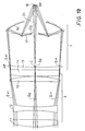
- Fig. 5 is a sectional view of an objective in a conventional reflecting microscope.
- Fig. 6 is a sectional view of a projection optical system according to a first embodiment of this invention.
- Fig. 7 is a diagram of the projection optical system of Fig. 6.
- Fig. 8(a) is a diagram of spherical aberration in the projection optical system of Figs. 6 and 7.
- Fig. 8(b) is a diagram of astigmatism in the projection optical system of Figs. 6 and 7.
- Fig. 8(c) is a diagram of distortion in the projection optical system of Figs. 6 and 7.
- Fig. 9 is a sectional view of a projection optical system according to a third embodiment of this invention.
- Fig. 10 is an enlarged view of part of the projection optical system of Fig. 9.
- Fig. 11 is a diagram of part of the projection optical system of Figs. 9 and 10.
- Fig. 1 shows a first conventional projection optical system of the pure refraction type, which includes a plurality of lenses made of optical glasses G and crystal optical materials M.
- the projection optical system of Fig. 1 generally produces a reduced image with a magnification of one-tenth (1/10).
- the transmittance is 23% at a light wavelength of 280 nm. This transmittance is too small to design an optical system.
- Fig. 2 shows a second conventional projection optical system of the refraction type, which includes a plurality of lenses G.
- an object or pattern 101 to be projected is illuminated by a bundle of parallel rays IL of partially coherent quasi-monochromatic light.
- This projection optical system is of the re-diffraction type in which diffracted light from a projected object forms point spectrums S1, S0, and S ⁇ 1 at a pupil surface and then forms again a spreading bundle of rays.
- the spectrums S1, S0, and S ⁇ 1 correspond to respective orders of diffraction.
- the spreading bundle of rays passes through the lenses G, and then forms an image by a combination of 0-order diffracted light, +1-order diffracted light, and -1-order diffracted light at an image surface.
- the areas including vertical lines represents 0-order diffracted light
- the areas including inclined lines sloping upward in the direction toward the right and the areas including inclined lines sloping downward in the direction toward the right denote +1-order diffracted light and -1-order diffracted light respectively.
- respective diffracted lights from the object or pattern 101 separate at a stop or diaphragm SP into point spectrums, passing through the succeeding lenses and then forming again a bundle of parallel rays.
- the parallel rays combine at a image surface 102, forming a projected pattern by interference fringes.
- the resolution limit of a projection optical system is given by the following Rayleigh's equation.
- D 0.61 ⁇ /NA
- NA represents the numerical aperture of the image side of the optical system
- ⁇ denotes the wavelength of the used light.
- the transmittance drops excessively.
- the transmittance is 23% at a light wavelength of 280 nm. This transmittance is generally unacceptable.
- Some optical materials of crystals such as a c r ystalline composite of TiF2, CaF2, and Kcl, exhibit transmittances of around 80% at a light wavelength of approximately 200 nm. It is generally difficult to increase the sizes of such efficient optical materials to an acceptable range and to produce a good optical surface. The number of such efficient optical materials is limited, so that the degree of freedom in designing is small. Furthermore, if an optical system of the re-diffraction type is formed by using a limited number of lenses made of such efficient optical material while maintaining an acceptable numerical aperture NA, it is generally difficult to adequately compensate aberration. Therefore, it is also difficult to form an acceptable optical system by using only refracting members. Accordingly, in the conventional optical systems of Figs. 1 and 2, if such efficient optical materials are used to form the lenses, the characteristics of processing are insufficient and accurate processing is usually difficult in ultraviolet and deep-ultraviolet region.
- Fig. 3 shows a third conventional projection optical system, which is of the reflection type.
- lights moved from an object O are reflected by mirrors 200 and 201 and form an image I with a magnification of unity (1/1) on a plane where the object O reside.
- the optical system of Fig. 3 constitutes a double telecentric system where principal rays on the object side and the image side are parallel to the optical axis.
- the optical system of Fig. 3 is composed of the reflecting mirrors only, there is no limitation on the wavelength of used light. Since the mirrors 200 and 201 are concentric about a point P on the axis of the image I, the tangential astigmatism is large and the image surface is curved, although the spherical aberration, the coma, and the distortion are compensated appropriately. In the application of the optical system of Fig.
- a slit is sometimes used to form an arcuate field at an image height where the tangential astigmatism and the sagittal astigmatism are equalized and the astigmatic difference is null, and the object O composed of the mask and the image surface I corresponding to the wafer are simultaneously scanned to produce a necessary projection field.
- the mirrors 200 and 201 can not be concentric as shown in Fig. 4.
- the center C2 of a lower portion of the mirror 200 deviates from the point C1 so that the aberration is increased in a region outside the axis.
- the object O and the image I can not reside on a common plane, it is necessary to scan the mask and the wafer independently and also to differentiate the scanning speeds in correspondence with the magnification. Since errors in the scanning speeds cause distortion of a projected image, it is necessary to precisely control the scanning speeds. As a projected image is finer, precise control of the scans is more difficult. Accordingly, if the optical system of Fig. 3 is used to produce a reduced image, there will be problems in respect of compensation for optical aberration and a mechanical structure.
- Fig. 5 shows an objective in a conventional reflecting microscope. As shown in Fig. 5, a bundle of rays emitted from an object 301 to be projected are successively reflected by mirrors 305 and 306 and then form a reduced image on a plane 302 opposite the object 301.
- the optical system of Fig. 5 is composed of the reflecting mirrors only, there is no limitation on the wavelength of used light. If the optical system of Fig. 5 forms a re-diffraction optical system under coherent illumination, 0-order diffracted light is blocked by the mirror 305 so that only +1-order diffracted light and -1-oder diffracted light are combined at the image or projection surface 302. As described clearly in "Optical and Electro-Optical Engineering Contact” Vol 23, No. 3, 1985, in this case, resulting interference fringes have a spatial frequency twice a desired spatial frequency so that it is difficult to project a fine pattern under coherent illumination.
- Fig. 6 shows a projection optical system according to a first embodiment of this invention.
- the optical system of Fig. 6 includes a refraction sub-system X and a cata-dioptric sub-system Y.
- the refraction sub-system X is generally composed of a convex lens 1, a concave lens 2, a convex lens 3, and a convex lens 4 made of quartz.
- An object 9 to be projected is placed on a focal plane F of the refraction sub-system X.
- the object 9 is illuminated by a light source (not shown).
- the object 9 consists of a member formed with a pattern to be transferred to a semiconductor wafer.
- the concave lens 2 follows the convex lens 1, and the convex lens 3 succeeds the concave lens 2.
- the convex lens 4 follows the convex lens 3.
- the lenses 1-4, and the object 9 are supported by suitable members (not shown).
- the cata-dioptric sub-system Y is placed opposite the object 9 with respect to the refraction sub-system X.
- the cata-dioptric sub system Y is generally composed of a refracting corrector plate 5 which in the following will be called phase compensating plate, a concave mirror 6, and a convex mirror 7 supported by suitable members (not shown).
- the phase compensating plate 5 is made of quarz.
- the concave mirror 6 has a central opening.
- the phase compensating plate 5 is the closest to the refraction sub-system X.
- the convex mirror 7 extends between the phase compensating plate 5 and the concave mirror 6.
- the phase compensating plate 5, the concave mirror 6, and the convex mirror 7 are arranged in rotation symmetry about a reference optical axis.
- the refracting sub-system X and the cata-dioptric sub-system Y are optically connected.
- the sub-systems X and Y have a common axis and also a common entrance pupil E on the common axis and mutually oppose with a small clearance formed therebetween.
- the convex lens 4 and the phase compensating plate 5 opposed to each other are mutually separate by a small gap.
- the concave mirror 6 and the convex mirror 7 are concentric about a point C of the entrance pupil E residing on an optical axis A.
- the left-hand side L of the convex lens 4, the right-hand side R of the phase compensating plate 5, and the concave mirror 6 are aspherical.
- Lights moved from a point of the object 9 pass through the lenses 1, 2, 3, and 4 while undergoing refraction. After passing through the convex lens 4, the lights form parallel rays and enter the phase compensating plate 5. The lights pass through the phase compensating plate 5 and are then reflected toward the convex mirror 7, that is, toward the phase compensating plate 5, by the concave mirror 6. Thereafter, the lights are reflected away from the phase compensating plate 5 by the convex mirror 7 and then pass through the opening of the concave mirror 6, finally forming a projected image 8 at a plane extending perpendicular to the reference axis A and at the rear of the concave mirror 6. A semiconductor wafer is generally placed on this plane of the image 8.
- Fig. 6 shows the case where the object 9 is illuminated by incoherent quasi-monochromatic lights.
- the image magnification B is given by the following equation.
- the entrance pupil E extends at a right-hand vertex of the phase compensating plate 5. Furthermore, a rear principal point of the refraction sub-system X and a front principal point of the cata-dioptric sub-system Y are chosen to coincide with each other. Accordingly, the angles ⁇ 1 and ⁇ 2 are equal so that the magnification B is solely determined by the ratio between the focal lengths f1 and f2. In other words, the refraction sub-system X and the cata-dioptric sub-system Y have a common entrance pupil E and equal effective diameters, so that the ratio between their numerical apertures determines the magnification B.
- a bundle of the incident lights from the object 9 is converted by the refraction sub-system X into parallel rays before entering the cata-dioptric sub-system Y.
- the numerical aperture of a total optical system which is composed of an optical combination of the refraction sub-system X and the cata-dioptric sub-system Y and which determines a resolution limit, is dependent on a projected image side composed of the cata-dioptric sub-system Y but is independent of an object side composed of the refraction sub-system X.
- a small numerical aperture of the refraction sub-system X is allowed so that it is possible to easily design and manufacture the refraction sub-system X.
- the object side refraction sub-system X serves as an afocal converter, enabling a small incident angle of the lights entering the image side cata-dioptric sub-system Y from the object 9 and thereby reducing optical aberrations in a range outside the optical axis.
- the spherical aberration can be reduced or removed by the previously-mentioned aspherical structures of the phase compensating plate 5, the concave mirror 6, and the lens 4.
- the compensation for the off-axis aberrations that is, the coma, the astigmatism, and the distortion, in the object side refraction sub-system X is independent of the compensation for the off-axis aberrations in the image side cata-dioptric sub-system Y, so that the aberrations can be small or null also in the optical combination of the sub-systems X and Y.
- the wavelengh of used light is 193 nm.
- the total system or optical combination of the refraction sub-system X and the cata-dioptric sub-system Y has a focal length f of 100 mm, an effective F number or aperture ratio of 1.3, and a magnification of 1/5.
- the lenses 1-4, the phase compensating plate 5, and the mirrors 6 and 7 are designed as follows.
- the characters r1 and r2 denote the radiuses of curvature of the refracting surfaces of the lens 1;
- the characters r3 and r4 denote the radiuses of curvature of the refracting surfaces of the lens 2;
- the characters r5 and r6 denote the radiuses of curvature of the refracting surfaces of the lens 3;
- the characters r7 and r8 denote the radiuses of curvature of the refracting surfaces of the lens 4;
- the characters r9 and r10 denote the radiuses of curvature of the opposite surfaces of the phase compensating plate 5;
- the character r11 denotes the radius of curvature of the reflecting surface of the concave mirror 6;
- the character r12 denotes the radius of curvature of the reflecting surface of the convex mirror 7;
- the character d1 denotes
- the aspherical sag quantity or deviation Z from a reference surface of the lens 4, the phase compensating plate 5, and the concave mirror 6 are represented by coefficients K, A4, A6, A8, and A10 in the following equation.
- K -e2
- the character e denotes the eccentricity
- the character h denotes the incident height of ray
- R l/r
- the character r denotes the radius of curvature.
- the coefficients K, A4, A6, A8, and A10 equal 0, -1.4500X10X ⁇ 8, 3.2000X10 ⁇ 13 0, and 0 respectively.
- the coefficients K, A4, A6, A8, and A10 equal 0, 2.4233X10 ⁇ 7, 2. 2897X10 ⁇ 11, 1.6851X10 ⁇ 15, and -1.3901X10 ⁇ 19 respectively.
- the coefficients K, A4, A6, A8, and A10 equal 0, 1.9573X10 ⁇ 9, 1.1446X10 ⁇ 12, 2.3025X10 ⁇ 16 and -6.0020X10 ⁇ 21 respectively.
- Fig. 8(a), Fig. 8(b), and Fig. 8(c) show the spherical aberration, the astigmatism, and the distortion respectively in this specific design of the projection optical system of Figs. 6 and 7.
- the astigmatism, the distortion, and the coma are reduced or prevented by the following arrangement and structure.
- the concave mirror 6 and the convex mirror 7 in the cata-dioptric sub-system Y are concentric about the center C of the entrance pupil E.
- the reflecting surface of the convex mirror 7 is spherical.
- the convex mirror 7 is concentric with the concave mirror 6 even in respect of lights traveling off the axis.
- the refracting members or lenses are made of quarz only, so that the transmittance is generally equal to or higher than 30% for a light having a wavelength of 193 nm.
- the refracting sub-system X has a large F number or a large aperture ratio so that the aberrations of the sub-system X can be easily compensated.
- the cata-dioptric sub-system Y is designed so that the related aberrations can be small or null. Furthermore, since the refraction sub-system X and the cata-dioptric sub-system Y are optically and coaxially connected and the phase compensating plate is placed in an end region of the cata-dioptric sub-system Y adjoining the refraction sub-system X, the spherical aberration, the coma, the astigmatism, and the distortion can be small or null.
- Figs. 9 and 10 show a projection optical system according to a second embodiment of this invention.
- the optical system of Figs. 9 and 10 includes an object side refraction sub-system X and an image side cata-dioptric sub-system Y.
- the refraction sub-system X is generally composed of a convex lens 11, a concave lens 12, a convex lens 13, and a convex lens 14 made of quartz.
- An object 19 to be projected is placed on a focal plane F of the refraction sub-system X.
- the object 19 is illuminated by a light source 20.
- the object 19 consists of a member formed with a pattern to be transferred to a semiconductor wafer.
- the concave lens 12 follows the convex lens 11, and the convex lens 13 succeeds the concave lens 12.
- the convex lens 14 follows the convex lens 13.
- the lenses 11-14, and the object 19 are supported by suitable members (not shown).
- the cata-dioptric sub-system Y is placed opposite the object 19 with respect to the refraction sub-system X.
- the cata-dioptric sub-system Y is generally composed of a refracting corrector plate 15 which in the following will be called phase compensating plate, a concave mirror 16, and a convex mirror 17 supported by suitable members (not shown).
- the phase compensating plate 15 is made of quarz.
- the concave mirror 16 has a central opening O1.
- the convex mirror 17 has a central opening O2.
- the phase compensating plate 15 is the closest to the refraction sub-system X.
- the convex mirror 17 extends between the phase compensating plate 15 and the concave mirror 16.
- the refracting sub-system X and the cata-dioptric sub-system Y are opposed and optically connected.
- the sub-systems X and Y have a common axis. On this common axis, the position of a diaphragm or pupil AP of each of the sub-systems X and Y coincides with the position of the centre C of the curved surface of the image side of the phase compensating plate 15.
- the phase compensating plate 15 is of rotation symmetry about the common axis or the reference optical axis.
- the concave mirror 16 and the convex mirror 17 are concentric about the center C of the curved surface of the phase compensating plate 15.
- the numerical aperture of the object side or the refraction sub-system X is preferably 0.076 and the numerical aperture of the image side or the cata-dioptric sub-system Y is preferably 0.38, and the magnification is preferably 1/5.
- the light source 20 emits coherent rays applied to the entire area of the object 19.
- the emitted lights are composed of convergent rays. Specifically, after the lights pass through the refraction sub-system X, they converge on the center C of the curved surface of the phase compensating plate 15. In this way, the object 19 is illuminated by coherent and convergent rays emitted from the light source 20.
- the incident angle which depends on the numerical aperture at the object side of the optical combination of the sub-systems X and Y is chosen to correspond to the angle ⁇ 1 of the +1-order diffracted light D+1 or the -1-order diffracted light D-1, so that +2-order diffracted light, -2-order diffracted light, and the higher-order diffracted lights will not enter the optical combination of the sub-system X and Y. In this way, only the 0-order diffracted light D0, the +1-order diffracted light D+1, and the -1-order diffracted light D-1 enter the optical combination of the sub-systems X and Y.
- the 0-order diffracted light D0, the +1-order diffracted light D+1, and the -1-order diffracted light D-1 from the object 19 pass through the lenses 11-14 and the phase compensating plate 15 while undergoing refraction. Then, the 0-order diffracted light D0, the +1-order diffracted light D+1, and the -1-order diffracted light D-1 separate and converge respectively on point spectrums S0, S+1, and S-1 in the diaphragm or pupil AP.
- the +1-order diffracted light D+1 and the -1-order diffracted light D-1 are reflected toward the phase compensating plate 15 or the convex mirror 17 by the concave mirror 16 and are then reflected away from the phase compensating plate 15 by the convex mirror 17.
- the +1-order diffracted light D+1 and the -1-order diffracted light D-1 pass throught the central opening O1 of the concave mirror 16 and move into the rear of the concave mirror 16.
- the 0-order diffracted light D0 After passing through the diaphragm or pupil AP, the 0-order diffracted light D0 successively passes through the central opening O2 of the convex mirror 17 and the central opening O1 of the concave mirror 16 and then moves into the rear of the concave mirror 16.
- the concave mirror 16 and the convex mirror 17 are concentrical about the center C of the diaphragm or pupil AP and the 0-order diffracted light D0 concentrates on this point C, the 0-order diffracted light D0 travels along a path similar to a supposed path along which the 0-order diffracted light D0 travels if the light D0 is reflected by the mirrors 16 and 17. Accordingly, the travel of the 0-order diffracted light D0 through the mirrors 16 and 17 without reflection does not increase the optical aberrations.
- the 0-order diffracted light D0, the +1-order diffracted light D+1, and the -1-order diffracted light D-1 meet, forming interference fringes which define an image on a plane IM perpendicular to the reference optical axis.
- a semiconductor wafer is generally placed at this plane IM.
- the cata-dioptric reflecting sub-system Y has a relatively large numerical aperture
- the refraction sub-system X has a relatively small numerical aperture
- the lenses 11-14, and the phase compensating plate 15 are made of quarz only.
- the total number of the lenses and the phase compensating plate is five. Accordingly, the transmittance of the projection optical system of Figs. 9 to 11 is equal to or higher than 30% for light having a wavelength of 200 nm.
- the refraction sub-system X and the cata-dioptric sub-system Y are optically connected.
- the sub-systems X and Y have a common axis.
- the center of the curved surface of the image side of the phase compensating plate 15 coincides with the position of the diaphragm or pupil AP.
- the object 19 to be projected is illuminated by coherent rays in such a manner that the coherent rays concentrate on the center of the diaphragm or pupil AP after they pass through the object 19.
- 9 to 11 includes a re-diffraction arrangement which forms an image by interference fringes of 0-order diffracted light, +1-order diffracted light, and -1-order diffracted light.
- the re-diffraction arrangement enables the projection of a fine pattern.
- an acceptable transmittance can be ensured for lights in ultraviolet and deep-ultraviolet ranges and a high resolution can be produced.
Landscapes
- Physics & Mathematics (AREA)
- General Physics & Mathematics (AREA)
- Optics & Photonics (AREA)
- Lenses (AREA)
- Exposure Of Semiconductors, Excluding Electron Or Ion Beam Exposure (AREA)
Claims (5)
- Ein optisches Projektionssystem, das umfaßt:(a) ein zu projizierendes Objekt (9);(b) ein Brechungs-Teilsystem (X), das brechende Glieder (1, 2, 3, 4) enthält, wobei das projizierte Objekt (9) an der vorderen Brennebene des Brechungs-Teilsystems (X) angeordnet ist;(c) ein katadioptrisches Teilsystem (Y), das eine Brechungskorrekturplatte (5), einen Konvexspiegel (7) sowie einen Konkavspiegel (6), die in Rotationssymmetrie um eine Bezugsachse (A) herum angeordnet sind, enthält, wobei der Konkavspiegel (6) eine zentrale Öffnung hat und das katadioptrische Teilsystem (Y) optisch mit dem Brechungs-Teilsystem (X) verbunden ist;(d) in welchem sich das Brechungs-Teilsystem (X) an einer Objektseite sowie das katadioptrische Teilsystem (Y) an einer Bildseite erstreckt; das Brechungs-Teilsystem (X) sowie das katadioptrische Teilsystem (Y) die genannte Bezugsachse als gemeinsame optische Achse (A) und eine gemeinsame Eintrittspupille (E) auf der gemeinsamen optischen Achse haben; der hintere Hauptpunkt des Brechungs-Teilsystems im wesentlichen mit dem vorderen Hauptpunkt des katadioptrischen Teilsystems (Y) zusammenfällt; die Brechungskorrekturplatte (5) an das Brechungs-Teilsystem (X) angrenzt; der Konkavspiegel (6) wenigstens einen Teil des durch die Brechungskorrekturplatte (5) getretenen Lichts zum Konvexspiegel (7) hin reflektiert; der Konvexspiegel (7) das genannte reflektierte Licht zurückwirft; die zentrale Öffnung des Konkavspiegels (6) dem durch den Konvexspiegel (7) zurückgeworfenen Licht ein Durchtreten durch den Konkavspiegel (6) erlaubt; die optische Kombination des Brechungs-Teilsystems (X) und des katadioptrischen Teilsystems (Y) wirksam ist, um dem projizierten Licht die Erzeugung eines Bildes (8) an einer Ebene, die sich rechtwinklig zur Bezugsachse (A) sowie an der Rückseite des Konkavspiegels (6) erstreckt, zu ermöglichen; sowie das Brechungs-Teilsystem (X) eine Funktion eines afokalen Wandlers mit Bezug zu dem katadioptrischen Teilsystem (Y) hat; und(e) in welchem das brechende, an das katadioptrische Teilsystem (Y) angrenzende Glied (4) eine dem katadioptrischen Teilsystem gegenüberliegende Fläche hat, deren Krümmung Null ist; die Brechungskorrekturplatte (5) eine dem Brechungs-Teilsystem (X) gegenüberliegende Fläche hat, deren Krümmung Null ist; und die besagten gegenüberliegenden Flächen mit einem geringen Abstand zwischen diesen koaxial angeordnet sind.
- Das optische Projektionssystem nach Anspruch 1, in welchem der Konvexspiegel (7) das gesamte, von dem Konkavspiegel (6) reflektierte Licht zurückwirft.
- Das optische Projektionssystem nach Anspruch 1, in welchem das Verhältnis zwischen den numerischen Aperturen des Brechungs-Teilsystems (X) und des katadioptrischen Teilsystems (Y) die Vergrößerung des Systems bestimmt.
- Ein optisches Projektionssystem, das umfaßt:(a) ein Brechungs-Teilsystem (X), das brechende Glieder (11, 12, 13, 14) enthält;(b) ein katadioptrisches Teilsystem (Y), das eine Brechungskorrekturplatte (15), einen Konvexspiegel (17) sowie einen Konkavspiegel (16) einschließt, wobei die Brechungskorrekturplatte (15) in Rotationssymmetrie um eine Bezugsachse herum angeordnet ist, der Konvexspiegel (17) sowie der Konkavspiegel (16) konzentrisch um ein Zentrum (C) der gekrümmten Fläche der Bildseite der Brechungskorrektplatte (15) herum angeordnet sind, der Konvexspiegel (17) eine zentrale Öffnung (O2) hat, der Konkavspiegel (16) eine zentrlae Öffnung (O1) hat und das katadioptrische Teilsystem (Y) optisch mit dem Brechungs-Teilsystem (X) verbunden ist;(c) in welchem das Brechungs-Teilsystem (X) sich an einer Objektseite und das katadioptrische Teilsystem sich an einer Bildseite erstrecken; das Brechungs-Teilsystem (X) sowie das katadioptrische Teilsystem (Y) die genannte Bezugsachse als gemeinsame optische Achse haben; die Brechungskorrekturplatte an das Brechungs-Teilsystem angrenzt; die Blende (AP) an der bildseitigen Fläche der Brechungskorrekturplatte (15) angeordnet ist; das Brechungs-Teilsystem (X) von einem Objekt (19) aus bewegtes Licht bricht und dem gebrochenen Licht ein Durchtreten durch die Brechungskorrekturplate (15) erlaubt; die zentrale Öffnung (O2) des Konvexspiegels (17) sowie die zentrale Öffnung (O1) des Konkavspiegels (16) einem Teil des durch die Brechungskorrekturplatte (15) getretenen Lichts ein Durchtreten durch den Konvexspiegel (17) sowie den Konkavspiegel (16) und ein Erreichen eines Bildpunkts ermöglichen; der Konkavspiegel (16) den restlichen Teil des Lichts zum Konvexspiegel (17) hin zurückwirft; der Konvexspiegel (17) das genannte zurückgeworfene Licht reflektiert; die zentrale Öffnung (O1) des Konkavspiegels (16) dem vom Konvexspiegel (17) reflektierten Licht eine Bewegung durch den Konkavspiegel (16) hindurch sowie das Erreichen des Bildpunkts erlaubt; und das den Bildpunkt erreichende Licht ein Bild an einer Ebene, die sich rechtwinklig zur Bezugsachse und an der Rückseite des Konkavspiegels (16) erstreckt, erzeugt;(d) ein zu projizierendes Objekt (19), das sich an der objektseitigen Brennebene des Brechungs-Teilsystems (X) erstreckt, wobei das Objekt (19) mit einer Struktur ausgestaltet ist, die eine vorbestimmte Raumfrequenz hat, welche ausgewählt ist, um aus einer kohärenten Beleuchtung gebeugtes Licht zu erzeugen;(e) in welchem das Brechungs-Teilsystem (X) eine Funktion eines afokalen Wandlers mit Bezug zum katadioptrischen Teilsystem (Y) hat; und(f) eine konvergentes, kohärentes Licht emittierende sowie das konvergente, köhärente Licht dem Objekt (19) zuführende Lichtquelle (20), wobei die Lichtquelle (20) wirksam ist, um das konvergente Licht am Zentrum (C) der gekrümmten Fläche der Bildseite der Brechungskorrekturplatte (15), nachdem das konvergente Licht durch das Objekt (19) tritt, zu konzentrieren.
- Das optische Projektionssystem nach Anspruch 4, in welchem das Brechungs-Teilsystem (X) eine numerische Apertur hat, die kleiner als die numerische Apertur des katadioptrischen Teilsystems (Y) ist.
Applications Claiming Priority (4)
| Application Number | Priority Date | Filing Date | Title |
|---|---|---|---|
| JP61102336A JPS62258414A (ja) | 1986-05-02 | 1986-05-02 | 精密複写用投影光学系 |
| JP102336/86 | 1986-05-02 | ||
| JP159050/86 | 1986-07-07 | ||
| JP61159050A JPS6314112A (ja) | 1986-07-07 | 1986-07-07 | 微細パタ−ン投影光学系 |
Publications (3)
| Publication Number | Publication Date |
|---|---|
| EP0243950A2 EP0243950A2 (de) | 1987-11-04 |
| EP0243950A3 EP0243950A3 (en) | 1989-02-08 |
| EP0243950B1 true EP0243950B1 (de) | 1993-03-24 |
Family
ID=26443043
Family Applications (1)
| Application Number | Title | Priority Date | Filing Date |
|---|---|---|---|
| EP87106243A Expired - Lifetime EP0243950B1 (de) | 1986-05-02 | 1987-04-29 | Optisches Projektionssystem |
Country Status (3)
| Country | Link |
|---|---|
| US (1) | US4757354A (de) |
| EP (1) | EP0243950B1 (de) |
| DE (1) | DE3784963T2 (de) |
Families Citing this family (41)
| Publication number | Priority date | Publication date | Assignee | Title |
|---|---|---|---|---|
| JP2754570B2 (ja) * | 1988-05-16 | 1998-05-20 | ミノルタ株式会社 | オートフォーカス可能な反射望遠レンズ鏡胴 |
| US5003345A (en) * | 1989-12-27 | 1991-03-26 | General Signal Corporation | Apparatus and method for aligning and focusing an image of a reticle onto a semiconductor wafer |
| US5136413A (en) * | 1990-11-05 | 1992-08-04 | Litel Instruments | Imaging and illumination system with aspherization and aberration correction by phase steps |
| US5291339A (en) * | 1990-11-30 | 1994-03-01 | Olympus Optical Co., Ltd. | Schwarzschild optical system |
| US5287218A (en) * | 1992-04-07 | 1994-02-15 | Hughes Aircraft Company | Re-imaging optical system including refractive and diffractive optical elements |
| US5448410A (en) * | 1992-07-31 | 1995-09-05 | International Business Machines Corporation | Variable magnification laser imaging system |
| JPH09311278A (ja) | 1996-05-20 | 1997-12-02 | Nikon Corp | 反射屈折光学系 |
| JP3395801B2 (ja) | 1994-04-28 | 2003-04-14 | 株式会社ニコン | 反射屈折投影光学系、走査型投影露光装置、及び走査投影露光方法 |
| USRE38438E1 (en) | 1994-08-23 | 2004-02-24 | Nikon Corporation | Catadioptric reduction projection optical system and exposure apparatus having the same |
| JPH08179204A (ja) * | 1994-11-10 | 1996-07-12 | Nikon Corp | 投影光学系及び投影露光装置 |
| JP3454390B2 (ja) | 1995-01-06 | 2003-10-06 | 株式会社ニコン | 投影光学系、投影露光装置及び投影露光方法 |
| RU2127868C1 (ru) * | 1996-06-26 | 1999-03-20 | Центральный научно-исследовательский институт "Электроприбор" | Способ изготовления электродной системы на сферической поверхности вакуумной камеры электростатического гироскопа |
| RU2140623C1 (ru) * | 1997-08-11 | 1999-10-27 | Центральный научно-исследовательский институт "Электроприбор" | Способ изготовления рельефных рисунков на сферических поверхностях и устройство для его осуществления |
| JP2000081367A (ja) | 1998-09-07 | 2000-03-21 | Nikon Corp | 光透過性光学部材、その製造方法、その評価方法、および光リソグラフィー装置 |
| KR20000034967A (ko) | 1998-11-30 | 2000-06-26 | 헨켈 카르스텐 | 수정-렌즈를 갖는 오브젝티브 및 투사 조명 장치 |
| US7151592B2 (en) * | 1999-02-15 | 2006-12-19 | Carl Zeiss Smt Ag | Projection system for EUV lithography |
| WO2001050171A1 (de) | 1999-12-29 | 2001-07-12 | Carl Zeiss | Projektionsobjektiv mit benachbart angeordneten asphärischen linsenoberflächen |
| WO2002044786A2 (en) * | 2000-11-28 | 2002-06-06 | Carl Zeiss Smt Ag | Catadioptric projection system for 157 nm lithography |
| TW538256B (en) * | 2000-01-14 | 2003-06-21 | Zeiss Stiftung | Microlithographic reduction projection catadioptric objective |
| JP2001228401A (ja) * | 2000-02-16 | 2001-08-24 | Canon Inc | 投影光学系、および該投影光学系による投影露光装置、デバイス製造方法 |
| JP2002083766A (ja) | 2000-06-19 | 2002-03-22 | Nikon Corp | 投影光学系、該光学系の製造方法、及び前記光学系を備えた投影露光装置 |
| KR20010113527A (ko) * | 2000-06-19 | 2001-12-28 | 시마무라 테루오 | 투영 광학계, 그 제조 방법 및 투영 노광 장치 |
| DE60206908T2 (de) * | 2001-01-09 | 2006-07-20 | Carl Zeiss Smt Ag | Projektionssystem für die extrem-ultraviolettlithographie |
| EP1615076A1 (de) * | 2001-01-09 | 2006-01-11 | Carl Zeiss SMT AG | Projektionssystem für die extrem-ultraviolettlithographie |
| US8208198B2 (en) | 2004-01-14 | 2012-06-26 | Carl Zeiss Smt Gmbh | Catadioptric projection objective |
| US7466489B2 (en) * | 2003-12-15 | 2008-12-16 | Susanne Beder | Projection objective having a high aperture and a planar end surface |
| WO2005059645A2 (en) * | 2003-12-19 | 2005-06-30 | Carl Zeiss Smt Ag | Microlithography projection objective with crystal elements |
| JP5420821B2 (ja) | 2004-01-14 | 2014-02-19 | カール・ツァイス・エスエムティー・ゲーエムベーハー | 反射屈折投影対物レンズ |
| US7463422B2 (en) * | 2004-01-14 | 2008-12-09 | Carl Zeiss Smt Ag | Projection exposure apparatus |
| US20080151365A1 (en) | 2004-01-14 | 2008-06-26 | Carl Zeiss Smt Ag | Catadioptric projection objective |
| KR20050080376A (ko) * | 2004-02-09 | 2005-08-12 | 삼성전자주식회사 | 투사광학계 및 그것을 갖는 화상 투사 장치 |
| WO2005098504A1 (en) | 2004-04-08 | 2005-10-20 | Carl Zeiss Smt Ag | Imaging system with mirror group |
| KR101213831B1 (ko) | 2004-05-17 | 2012-12-24 | 칼 짜이스 에스엠티 게엠베하 | 중간이미지를 갖는 카타디옵트릭 투사 대물렌즈 |
| JP2006119490A (ja) * | 2004-10-25 | 2006-05-11 | Canon Inc | 反射屈折型投影光学系及び当該反射屈折型投影光学系を有する露光装置、デバイス製造方法 |
| US20080198455A1 (en) * | 2005-02-25 | 2008-08-21 | Carl Zeiss Smt Ag | Optical System, In Particular Objective Or Illumination System For A Microlithographic Projection Exposure Apparatus |
| US20080112927A1 (en) * | 2006-10-23 | 2008-05-15 | Genegrafts Ltd. | Cells and methods utilizing same for modifying the electrophysiological function of excitable tissues |
| US7633689B2 (en) * | 2007-07-18 | 2009-12-15 | Asml Holding N.V. | Catadioptric optical system for scatterometry |
| TWI545365B (zh) | 2015-02-17 | 2016-08-11 | 大立光電股份有限公司 | 取像鏡頭組、取像裝置及電子裝置 |
| TWI626487B (zh) | 2017-03-31 | 2018-06-11 | 大立光電股份有限公司 | 光學影像鏡頭系統組、取像裝置及電子裝置 |
| TWI640809B (zh) | 2017-05-19 | 2018-11-11 | 大立光電股份有限公司 | 攝影鏡片系統、取像裝置及電子裝置 |
| CN112764196B (zh) * | 2021-01-08 | 2022-03-11 | 广景视睿科技(深圳)有限公司 | 一种双远心投影镜头及汽车的抬头显示装置 |
Family Cites Families (8)
| Publication number | Priority date | Publication date | Assignee | Title |
|---|---|---|---|---|
| GB618253A (en) * | 1946-05-01 | 1949-02-18 | Wray Optical Works Ltd | Improvements in or relating to optical objectives |
| US2520633A (en) * | 1948-10-20 | 1950-08-29 | Polaroid Corp | Optical system |
| US3748015A (en) * | 1971-06-21 | 1973-07-24 | Perkin Elmer Corp | Unit power imaging catoptric anastigmat |
| JPS5951229B2 (ja) * | 1978-07-11 | 1984-12-12 | マブチモ−タ−株式会社 | 直流電動機のブリツジ式ガバナ−起動回路 |
| JPS5712966A (en) * | 1980-06-21 | 1982-01-22 | Tomie Numahata | Mixed cake from rice and barley |
| US4425037A (en) * | 1981-05-15 | 1984-01-10 | General Signal Corporation | Apparatus for projecting a series of images onto dies of a semiconductor wafer |
| JPS5825637A (ja) * | 1981-08-08 | 1983-02-15 | Canon Inc | 投影焼付装置 |
| US4600265A (en) * | 1983-01-27 | 1986-07-15 | Pilkington P.E. Limited | Infra-red optical systems |
-
1987
- 1987-04-28 US US07/043,620 patent/US4757354A/en not_active Expired - Fee Related
- 1987-04-29 EP EP87106243A patent/EP0243950B1/de not_active Expired - Lifetime
- 1987-04-29 DE DE8787106243T patent/DE3784963T2/de not_active Expired - Fee Related
Non-Patent Citations (1)
| Title |
|---|
| "Handbook of Optics", Optical Society of America, W.G. Driscoll and W. Vaughan Eds., McGraw-Hill, 1978, page 2.69, Section 68. * |
Also Published As
| Publication number | Publication date |
|---|---|
| US4757354A (en) | 1988-07-12 |
| EP0243950A3 (en) | 1989-02-08 |
| DE3784963D1 (de) | 1993-04-29 |
| DE3784963T2 (de) | 1993-07-15 |
| EP0243950A2 (de) | 1987-11-04 |
Similar Documents
| Publication | Publication Date | Title |
|---|---|---|
| EP0243950B1 (de) | Optisches Projektionssystem | |
| USRE39024E1 (en) | Exposure apparatus having catadioptric projection optical system | |
| US6157498A (en) | Dual-imaging optical system | |
| KR100412174B1 (ko) | 반사굴절광학계및노광장치 | |
| US4685777A (en) | Reflection and refraction optical system | |
| US7426082B2 (en) | Catadioptric projection objective with geometric beam splitting | |
| US4861148A (en) | Projection optical system for use in precise copy | |
| US4812028A (en) | Reflection type reduction projection optical system | |
| US5689377A (en) | Catadioptric optical system and exposure apparatus having the same | |
| US7092168B2 (en) | Projection optical system and projection exposure apparatus | |
| US4747678A (en) | Optical relay system with magnification | |
| US4688904A (en) | Reflecting optical system | |
| JPH07111512B2 (ja) | 補償型光学システム | |
| JPH04214516A (ja) | 投影レンズ系 | |
| EP0732605A2 (de) | Belichtungsapparat | |
| US5257139A (en) | Reflection reduction projection optical system | |
| USRE38438E1 (en) | Catadioptric reduction projection optical system and exposure apparatus having the same | |
| US5673135A (en) | Scanning projection optical device | |
| JP2002244046A (ja) | カタディオプトリック縮小レンズ | |
| JP2000098228A (ja) | 投影露光装置及び露光方法、並びに反射縮小投影光学系 | |
| US6208473B1 (en) | Catadioptric projection lens | |
| JPH0562721B2 (de) | ||
| EP0581585B1 (de) | Verkleinerndes katadioptrisches Projektionssystem | |
| EP0527043B1 (de) | Verkleinerndes katadioptrisches Projektionssystem | |
| US7046459B1 (en) | Catadioptric reductions lens |
Legal Events
| Date | Code | Title | Description |
|---|---|---|---|
| PUAI | Public reference made under article 153(3) epc to a published international application that has entered the european phase |
Free format text: ORIGINAL CODE: 0009012 |
|
| 17P | Request for examination filed |
Effective date: 19870429 |
|
| AK | Designated contracting states |
Kind code of ref document: A2 Designated state(s): DE FR GB |
|
| PUAL | Search report despatched |
Free format text: ORIGINAL CODE: 0009013 |
|
| AK | Designated contracting states |
Kind code of ref document: A3 Designated state(s): DE FR GB |
|
| RHK1 | Main classification (correction) |
Ipc: G02B 17/08 |
|
| 17Q | First examination report despatched |
Effective date: 19910227 |
|
| GRAA | (expected) grant |
Free format text: ORIGINAL CODE: 0009210 |
|
| AK | Designated contracting states |
Kind code of ref document: B1 Designated state(s): DE FR GB |
|
| REF | Corresponds to: |
Ref document number: 3784963 Country of ref document: DE Date of ref document: 19930429 |
|
| EN | Fr: translation not filed | ||
| PG25 | Lapsed in a contracting state [announced via postgrant information from national office to epo] |
Ref country code: FR Effective date: 19930813 |
|
| PLBE | No opposition filed within time limit |
Free format text: ORIGINAL CODE: 0009261 |
|
| STAA | Information on the status of an ep patent application or granted ep patent |
Free format text: STATUS: NO OPPOSITION FILED WITHIN TIME LIMIT |
|
| 26N | No opposition filed | ||
| REG | Reference to a national code |
Ref country code: FR Ref legal event code: ST |
|
| REG | Reference to a national code |
Ref country code: GB Ref legal event code: 746 Effective date: 19951123 |
|
| PGFP | Annual fee paid to national office [announced via postgrant information from national office to epo] |
Ref country code: GB Payment date: 19960422 Year of fee payment: 10 |
|
| PG25 | Lapsed in a contracting state [announced via postgrant information from national office to epo] |
Ref country code: GB Effective date: 19970429 |
|
| GBPC | Gb: european patent ceased through non-payment of renewal fee |
Effective date: 19970429 |
|
| PGFP | Annual fee paid to national office [announced via postgrant information from national office to epo] |
Ref country code: DE Payment date: 20020508 Year of fee payment: 16 |
|
| PG25 | Lapsed in a contracting state [announced via postgrant information from national office to epo] |
Ref country code: DE Free format text: LAPSE BECAUSE OF NON-PAYMENT OF DUE FEES Effective date: 20031101 |