EP0243874B1 - Dispositif de commande du début et de la durée d'injection du combustible pour un moteur à combustion interne - Google Patents
Dispositif de commande du début et de la durée d'injection du combustible pour un moteur à combustion interne Download PDFInfo
- Publication number
- EP0243874B1 EP0243874B1 EP87105933A EP87105933A EP0243874B1 EP 0243874 B1 EP0243874 B1 EP 0243874B1 EP 87105933 A EP87105933 A EP 87105933A EP 87105933 A EP87105933 A EP 87105933A EP 0243874 B1 EP0243874 B1 EP 0243874B1
- Authority
- EP
- European Patent Office
- Prior art keywords
- adjusting device
- carrier body
- shaft
- ram
- machined
- Prior art date
- Legal status (The legal status is an assumption and is not a legal conclusion. Google has not performed a legal analysis and makes no representation as to the accuracy of the status listed.)
- Expired - Lifetime
Links
- 238000002485 combustion reaction Methods 0.000 title claims abstract description 15
- 238000002347 injection Methods 0.000 title claims description 16
- 239000007924 injection Substances 0.000 title claims description 16
- 239000000446 fuel Substances 0.000 title claims description 3
- 230000001154 acute effect Effects 0.000 claims description 3
- 239000012530 fluid Substances 0.000 abstract 1
- 238000010276 construction Methods 0.000 description 3
- 230000001419 dependent effect Effects 0.000 description 2
- 238000004519 manufacturing process Methods 0.000 description 2
- 230000006978 adaptation Effects 0.000 description 1
- 230000005540 biological transmission Effects 0.000 description 1
- 210000000988 bone and bone Anatomy 0.000 description 1
- 238000006073 displacement reaction Methods 0.000 description 1
- 238000009434 installation Methods 0.000 description 1
Images
Classifications
-
- F—MECHANICAL ENGINEERING; LIGHTING; HEATING; WEAPONS; BLASTING
- F02—COMBUSTION ENGINES; HOT-GAS OR COMBUSTION-PRODUCT ENGINE PLANTS
- F02M—SUPPLYING COMBUSTION ENGINES IN GENERAL WITH COMBUSTIBLE MIXTURES OR CONSTITUENTS THEREOF
- F02M59/00—Pumps specially adapted for fuel-injection and not provided for in groups F02M39/00 -F02M57/00, e.g. rotary cylinder-block type of pumps
- F02M59/20—Varying fuel delivery in quantity or timing
Definitions
- the invention relates to an adjusting device according to the preamble of claim 1.
- a delivery start adjustment device for an in-line injection pump of an internal combustion engine is known, which is integrated into the housing of the in-line injection pump.
- a tappet which is arranged between the tappet rod and the camshaft integrated in the in-line injection pump, is moved tangentially to the camshaft by a device which can be adjusted via two eccentrically mounted adjusting pins.
- an additional overall height of the in-line injection pump is required to accommodate the adjusting device spatially.
- the eccentrically mounted adjustment pins interacting with the adjustment device must be manufactured in completely identical construction and must be aligned precisely with one another to ensure trouble-free operation.
- a generic delivery start adjustment device is known from GB-A 2 161 545.
- This conveying start adjustment device has a support body transversely to the direction of movement of the plunger, in which the plunger is movably mounted in a bore arranged axially parallel to the plunger movement direction.
- This adjustment device requires high construction costs due to the additional mounting holes for the support body. In addition, the adjustment accuracy is limited, since small displacements of the support body cause large start-up adjustments.
- the object of the invention is to provide an adjusting device with which a plunger, which can be moved radially to the shaft by a cam arranged on a shaft, can be displaced tangentially to the shaft, the adjusting device being mechanically simple and space-saving and easy in an internal combustion engine can be installed, and an exact delivery start adjustment is made possible.
- the adjusting device has a support body which is slidably mounted in a fixed housing at an acute angle to the radial direction of movement of the plunger caused by the cam and an extension is arranged on the support body in the shaft-side axial extension of the support body, which the shaft and the cam is tangentially covered on one side in a partial section without contact, a mechanically simple construction is provided which is easy to install and space-saving.
- the bore in the housing for example of an internal combustion engine, which is necessary anyway for guiding the tappet, can already be produced during the housing production without additional effort in accordance with the requirements given by the installation of the adjusting device according to the invention.
- the adjustment device which essentially consists of the supporting body, likewise does not pose any special manufacturing requirements and can be manufactured in a simple manner as a normal series part.
- the delivery start adjustment accuracy is high, since a corresponding transmission ratio of the movements is set by the arrangement of the support body at an acute angle to the direction of movement of the plunger.
- the extension has a recess in the end region pointing away from the support body, into which an actuating shaft arranged transversely to the extension engages with a nose, the nose in the region interacting with the recess having a surface contour that has a play-free contact surface in a predetermined range of rotation to the recess.
- This design provides a simple device for the axial adjustment of one or more supporting bodies.
- the actuating shaft is mounted axially parallel to the camshaft in suitable bearing devices.
- the already existing bearing blocks of the camshaft, in which only an additional hole has to be drilled, are suitable for this.
- the actuating shaft in turn is now turned via a corresponding lever on which an adjusting piston is articulated.
- the adjusting piston can be adjusted, for example, when using the adjusting device as a delivery start adjustment device for an injection pump element of an internal combustion engine by the known adaptation groups, such as load-dependent delivery start or boost pressure-dependent delivery start adjustment group. This can be done on series parts like them used for example in distributor injection pumps.
- the adjusting device according to the invention can be used in particular in the case of individual injection pump elements which are inserted directly into the internal combustion engine housing.
- the adjustment device is also intended to be installed in in-line injection pumps.
- both components are secured by pins which engage in corresponding grooves in the housing or the support body.
- the adjustment device according to the invention can be used both for adjusting the start of delivery of the injection pump elements of an internal combustion engine and for changing the valve timing.
- both the inlet and outlet valves are adjusted alone or together, but corresponding adjustment devices.
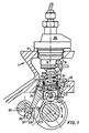
- a central shaft 2 serving as a camshaft is arranged in the housing 1 of an internal combustion engine cams 3 arranged next to one another actuate the gas exchange valves and the injection pump elements 29 of the internal combustion engine.
- An injection pump element 29 is fastened on a flange 4 of the housing 1.
- the flange 4 is arranged at right angles to a connecting line 5 to the camshaft 2.
- An opening 6 is machined into the flange 4, through which a push rod 7 of an injection pump element 29 is passed.
- the push rod 7 ends on the camshaft side in a plate 8, on which a spring 9 pointing toward the injection pump element 28 is supported.
- a push rod 10 is arranged in the axial extension of the connecting line 5.
- the plunger 10 has a surface 11 on the push rod side, which is arranged parallel to the plate 8 and on which the plate 8 is supported.
- the distance a and b between the outer diameter of the plate 8 and the inner diameter of an annular extension 12 of the surface 11 is such that it does not become zero over the entire tangential adjustment range of the plunger 10.
- annular extension 12 a On the side of the surface 11 facing the camshaft 2 there is also an annular extension 12 a.
- annular extension 12 a two bores are machined axially parallel to the camshaft 2, into which a shaft 13 is inserted, on which an impeller 14 is mounted within the annular extension.
- This impeller 14, which is aligned axially parallel to the camshaft 2 runs on the radial circumference of the camshaft 2 or the cam 3 and moves the tappet 10 and correspondingly the tappet rod 7 along the connecting line 5 in accordance with the surface contour of the camshaft 2 or the cam 3.
- the plunger 10 is guided in a support body 15, which is arranged in a recess 16 of the housing 1.
- the direction of movement of the support body 15, which can be represented by its center line 17, is inclined by an angle ⁇ to the connecting line 5.
- a bore 18 which is parallel to the connecting line 5 and which corresponds to the outer diameter of the plunger 10 is machined into the support body 15.
- the support body 15 also has a radial bore 19 into which a pin 20 is pressed.
- the support body 15 is preferably manufactured as a cylindrical component.
- the support body 15 is also possible according to the invention to secure the support body 15, which is manufactured as a cylindrical component, against rotation by means of sliding webs 30, which are supported on both sides of a cam 3 on the base circle of camshaft 2. If the outer contour of the support body deviates from a circular shape - for example in the case of a rectangular outer contour - then a rotation lock can be dispensed with, since the support body is then guided in a correspondingly designed recess 16 so that it cannot rotate.
- a radial blind hole 22 is machined in the area of the surface 11, in which a pin 23 is also inserted.
- the pin 23 protrudes with its end protruding from the blind hole 22 into a groove 24 which is axially parallel in the recess 16 of the support body 15 is incorporated into the connecting line 5.
- the plunger 10 is thus also secured against rotation with respect to the supporting body 15 and with respect to the housing 1.
- the support body 15 is moved axially in the direction of the center line 17 by an actuating shaft 25 which engages with a lug 26 in a recess 27 which is let into an extension 28 of the support body 15.
- the actuating shaft 25 is arranged axially parallel to the camshaft 2 and is provided with at least one lever, by which the actuating shaft 25 can be rotated through predetermined angular ranges. This rotation is carried out by an adjusting piston, not shown, which can be adjusted hydraulically, for example, by the controllable fuel pressure.
- the support body 15 is displaced in the direction of the flange 4.
- the plunger 10 is displaced such that the distance b is reduced and the distance a is increased.
- the bone shaft 2 rotates, for example, in the direction of the arrow shown, such an adjustment of the plunger 10 means a shift in the start of delivery in the "early” direction.
- a movement of the actuating shaft 25 directed against the arrow would accordingly cause the start of delivery to be shifted towards the "late” direction if the camshaft rotation direction remains unchanged.
Landscapes
- Engineering & Computer Science (AREA)
- Chemical & Material Sciences (AREA)
- Combustion & Propulsion (AREA)
- Mechanical Engineering (AREA)
- General Engineering & Computer Science (AREA)
- Fuel-Injection Apparatus (AREA)
- Valve Device For Special Equipments (AREA)
- Electrical Control Of Ignition Timing (AREA)
- Valve-Gear Or Valve Arrangements (AREA)
- Electrical Control Of Air Or Fuel Supplied To Internal-Combustion Engine (AREA)
Claims (6)
Priority Applications (1)
| Application Number | Priority Date | Filing Date | Title |
|---|---|---|---|
| AT87105933T ATE63975T1 (de) | 1986-04-26 | 1987-04-23 | Verstelleinrichtung fuer foerderbeginn und steuerzeiten einer brennkraftmaschine. |
Applications Claiming Priority (2)
| Application Number | Priority Date | Filing Date | Title |
|---|---|---|---|
| DE3614281 | 1986-04-26 | ||
| DE19863614281 DE3614281A1 (de) | 1986-04-26 | 1986-04-26 | Verstelleinrichtung fuer foerderbeginn und steuerzeiten einer brennkraftmaschine |
Publications (3)
| Publication Number | Publication Date |
|---|---|
| EP0243874A2 EP0243874A2 (fr) | 1987-11-04 |
| EP0243874A3 EP0243874A3 (en) | 1989-09-27 |
| EP0243874B1 true EP0243874B1 (fr) | 1991-05-29 |
Family
ID=6299665
Family Applications (1)
| Application Number | Title | Priority Date | Filing Date |
|---|---|---|---|
| EP87105933A Expired - Lifetime EP0243874B1 (fr) | 1986-04-26 | 1987-04-23 | Dispositif de commande du début et de la durée d'injection du combustible pour un moteur à combustion interne |
Country Status (4)
| Country | Link |
|---|---|
| US (1) | US4760831A (fr) |
| EP (1) | EP0243874B1 (fr) |
| AT (1) | ATE63975T1 (fr) |
| DE (2) | DE3614281A1 (fr) |
Families Citing this family (13)
| Publication number | Priority date | Publication date | Assignee | Title |
|---|---|---|---|---|
| DE3821888A1 (de) * | 1988-06-29 | 1990-01-11 | Pierburg Gmbh | Brennstoffpumpe |
| DE3910794C2 (de) * | 1989-04-04 | 1995-05-11 | Kloeckner Humboldt Deutz Ag | Dieselbrennkraftmaschine |
| JP2843614B2 (ja) * | 1989-09-29 | 1999-01-06 | ヤマハ発動機株式会社 | 2サイクルディーゼルエンジン |
| DE3935883C2 (de) * | 1989-10-27 | 1996-08-01 | Kloeckner Humboldt Deutz Ag | Viertakt-Dieselbrennkraftmaschine |
| DE4118555A1 (de) * | 1991-06-06 | 1992-12-10 | Bosch Gmbh Robert | Foerderbeginnverstelleinrichtung einer kraftstoffeinspritzpumpe |
| DE4212255C2 (de) * | 1992-04-11 | 1996-12-19 | Daimler Benz Ag | Anordnung einer Kraftstoff-Einspritzvorrichtung am Gehäuse einer Brennkraftmaschine |
| DE4227851A1 (de) * | 1992-08-22 | 1994-02-24 | Bosch Gmbh Robert | Kraftstoffeinspritzpumpe für Brennkraftmaschinen |
| DE4410124A1 (de) * | 1994-03-24 | 1995-09-28 | Schaeffler Waelzlager Kg | Verdrehsicherung eines Traversenstößels einer Ventilbetätigungseinrichtung einer Brennkraftmaschine |
| DE19548808A1 (de) * | 1995-12-27 | 1997-07-03 | Mwp Mahle J Wizemann Pleuco Gm | Übertragungselement, insbesondere Rollenstößel zur Betätigung eines Ventils für insbesondere einen Verbrennungsmotor |
| KR100992823B1 (ko) * | 2007-12-13 | 2010-11-08 | 기아자동차주식회사 | 연료펌프 세트 |
| US8646436B2 (en) * | 2010-07-06 | 2014-02-11 | Toyota Boshoku Kabushiki Kaisha | Fuel pump attachment structure |
| US9435328B2 (en) * | 2011-01-06 | 2016-09-06 | Continental Automotive Systems Inc. | Variable stroke control structure for high pressure fuel pump |
| US10677210B2 (en) * | 2017-11-30 | 2020-06-09 | Cfr Engines Canada Ulc | Air-assisted fuel injection system for ignition quality determination |
Family Cites Families (27)
| Publication number | Priority date | Publication date | Assignee | Title |
|---|---|---|---|---|
| FR680396A (fr) * | 1928-09-29 | 1930-04-29 | Burmeister & Wains Mot Mask | Perfectionnements aux pompes à combustible pour moteurs à combustion interne |
| US2070933A (en) * | 1932-02-27 | 1937-02-16 | Taylor John Leonard | Engine governing system |
| GB446722A (en) * | 1934-10-30 | 1936-04-30 | Ernest Arthur Franks | Improvements in or relating to reciprocating pumps |
| US2183950A (en) * | 1935-05-10 | 1939-12-19 | David V Ackerman | Adjustable slip cam |
| DE875105C (de) * | 1943-10-24 | 1953-04-30 | Daimler Benz Ag | Schwenkbar angeordneter Stoessel, insbesondere Ventilstoessel fuer umsteuerbare Brennkraftmaschinen |
| GB637325A (en) * | 1947-08-13 | 1950-05-17 | Hobson Ltd H M | Improvements in mechanism for imparting a variable stroke to a reciprocating member |
| GB678026A (en) * | 1949-02-15 | 1952-08-27 | Semt | Improvements in and relating to fuel-injection pumps for internal combustion engines |
| AT189447B (de) * | 1949-12-28 | 1957-03-25 | Anton Dipl Ing Dr T Pischinger | Brennstoffeinspritzpumpe für Einspritzbrennkraftmaschinen |
| GB772392A (en) * | 1954-07-24 | 1957-04-10 | Burmeister & Wains Mot Mask | Improvements in and relating to a method of operating turbo-charged two-stroke cycleinternal combustion engines, and arrangement in such engines for carrying out the method |
| US3040723A (en) * | 1959-03-19 | 1962-06-26 | Daimler Benz Ag | Fuel-injection adjusting device |
| FR1278145A (fr) * | 1960-10-27 | 1961-12-08 | Perfectionnements apportés aux pompes d'injection de combustible comportant des moyens servant au réglage de l'avance de l'injection | |
| US3079904A (en) * | 1961-03-20 | 1963-03-05 | Thompson Ramo Wooldridge Inc | Fuel distributor with acceleration enrichment |
| FR1342703A (fr) * | 1963-01-10 | 1963-11-08 | Sulzer Ag | Commande de soupape pour moteurs à combustion interne à pistons |
| DE1214499B (de) * | 1963-03-13 | 1966-04-14 | Hansa Metallwerke Ag | Hebelventil mit einem zur Verbindung von Bedienungshebel und Ventilverschlusskoerper dienenden Kniehebel |
| AT256555B (de) * | 1964-09-09 | 1967-08-25 | Friedmann & Maier Ag | Einspritzpumpe für Brennkraftmaschinen |
| GB1328096A (en) * | 1969-12-09 | 1973-08-30 | Simms Group Research Dev Ltd | Fuel injection pumps |
| US4100903A (en) * | 1976-12-13 | 1978-07-18 | Stanadyne, Inc. | Rotary distributor fuel injection pump |
| DE2723969C2 (de) * | 1977-05-27 | 1983-02-17 | Klöckner-Humboldt-Deutz AG, 5000 Köln | Kraftstoffeinspritzpumpe für Brennkraftmaschinen |
| FR2417642A1 (fr) * | 1978-02-20 | 1979-09-14 | List Hans | Moteur a injection de carburant, notamment moteur diesel avec installation de reglage de l'instant d'injection |
| US4335685A (en) * | 1979-10-19 | 1982-06-22 | Caterpillar Tractor Co. | Lifter assembly |
| DE3105205A1 (de) * | 1981-02-13 | 1982-12-30 | Günter 8543 Hilpoltstein Elsbett | Kolbenpumpe zum foerdern von fluessigkeiten, insbesondere kraftstoff fuer hubkolben-brennkraftmaschinen |
| DK147186C (da) * | 1981-05-06 | 1984-10-29 | B & W Diesel As | Drivmekanisme for en braendselspumpe til en omstyrbar totaktsmotor |
| GB2103725B (en) * | 1981-07-10 | 1985-03-06 | Lucas Ind Plc | Fuel injection pump |
| DE3206429C2 (de) * | 1982-02-23 | 1983-12-22 | Daimler-Benz Ag, 7000 Stuttgart | Hydraulische Verstelleinrichtung zur Beeinflussung des Einspritzbeginns einer für selbstzündende Brennkraftmaschinen vorgesehenen Einspritzpumpe |
| JPS59128970A (ja) * | 1983-01-14 | 1984-07-25 | Mitsubishi Heavy Ind Ltd | 燃料噴射ポンプ駆動装置 |
| JPH066887B2 (ja) * | 1983-07-25 | 1994-01-26 | マツダ株式会社 | エンジンのバルブタイミング制御装置 |
| DE3425522A1 (de) * | 1984-07-11 | 1986-01-23 | Mtu Motoren- Und Turbinen-Union Friedrichshafen Gmbh, 7990 Friedrichshafen | Dieselmotor mit jedem zylinder zugeordneter einspritzpumpe |
-
1986
- 1986-04-26 DE DE19863614281 patent/DE3614281A1/de not_active Withdrawn
-
1987
- 1987-04-20 US US07/040,140 patent/US4760831A/en not_active Expired - Fee Related
- 1987-04-23 AT AT87105933T patent/ATE63975T1/de not_active IP Right Cessation
- 1987-04-23 DE DE8787105933T patent/DE3770330D1/de not_active Expired - Fee Related
- 1987-04-23 EP EP87105933A patent/EP0243874B1/fr not_active Expired - Lifetime
Also Published As
| Publication number | Publication date |
|---|---|
| EP0243874A2 (fr) | 1987-11-04 |
| DE3770330D1 (de) | 1991-07-04 |
| ATE63975T1 (de) | 1991-06-15 |
| US4760831A (en) | 1988-08-02 |
| EP0243874A3 (en) | 1989-09-27 |
| DE3614281A1 (de) | 1987-10-29 |
Similar Documents
| Publication | Publication Date | Title |
|---|---|---|
| EP0243874B1 (fr) | Dispositif de commande du début et de la durée d'injection du combustible pour un moteur à combustion interne | |
| EP0163046B1 (fr) | Dispositif pour varier la phase entre un arbre, spécialement un arbre à cames, et un arbre de commande | |
| DE4227853C2 (de) | Kraftstoffeinspritzpumpe für Brennkraftmaschinen | |
| DE3540052C2 (fr) | ||
| DE3930157A1 (de) | Einrichtung zur verstellung der drehwinkelzuordnung einer nockenwelle zu ihrem antriebselement | |
| EP0469334B1 (fr) | Procédé pour changer la position angulaire des arbres d'un moteur à combustion interne | |
| DE60317853T2 (de) | Kurbelwelle einer Brennkraftmaschine | |
| DE102009024026A1 (de) | Steuerventil zum Steuern von Druckmittelströmen mit integriertem Rückschlagventil | |
| DE19908286A1 (de) | Variable Ventilsteuerung für Brennkraftmaschinen | |
| DE102016114978A1 (de) | Pleuel für eine Brennkraftmaschine mit variabler Verdichtung | |
| DE4237777C2 (de) | Ventilbetätigungseinrichtung | |
| DE102009006894B4 (de) | Vorrichtung zur Schaltbetätigung eines hydraulischen Ventilspielausgleichselements | |
| EP0265460B1 (fr) | Pompe d'injection de carburant pour moteurs a combustion interne | |
| DE602004006121T2 (de) | Brennkraftmaschine mit variabler und hydraulischer Ventilsteuerung durch Kipphebel | |
| EP0468202B1 (fr) | Poussoir à galet avec compensateur de jeu hydraulique | |
| WO1999056008A1 (fr) | Element d'appui pour un basculeur d'un mecanisme de distribution d'un moteur a combustion interne | |
| DE19611365A1 (de) | Vorrichtung zur relativen Winkelverstellung einer Nockenwelle | |
| WO1992020907A1 (fr) | Dispositif de reglage de l'angle de rotation d'un arbre a cames par rapport a son element de d'entrainement | |
| DE19701203A1 (de) | Variable Ventilsteuerung für Brennkraftmaschinen | |
| EP2744987A1 (fr) | Arbre à cames pour la commande des soupapes d'un moteur à combustion interne | |
| DE102006005333B4 (de) | Ventiltrieb für eine Brennkraftmaschine | |
| EP0262167B1 (fr) | Pompe d'injection de carburant pour moteurs a combustion interne | |
| DE4037089C2 (de) | Hydraulische Einrichtung zum Verdrehen der Nockenwelle einer Brennkraftmaschine | |
| DE4229201A1 (de) | Vorrichtung zum Verstellen der Nockenwellen-Steuerzeiten | |
| WO2014183751A1 (fr) | Soupape centrale pourvue d'un piston de commande destiné à commander l'alimentation en huile pour un dispositif de réglage d'arbre à cames |
Legal Events
| Date | Code | Title | Description |
|---|---|---|---|
| PUAI | Public reference made under article 153(3) epc to a published international application that has entered the european phase |
Free format text: ORIGINAL CODE: 0009012 |
|
| AK | Designated contracting states |
Kind code of ref document: A2 Designated state(s): AT DE FR GB IT NL |
|
| PUAL | Search report despatched |
Free format text: ORIGINAL CODE: 0009013 |
|
| AK | Designated contracting states |
Kind code of ref document: A3 Designated state(s): AT DE FR GB IT NL |
|
| 17P | Request for examination filed |
Effective date: 19890817 |
|
| 17Q | First examination report despatched |
Effective date: 19900308 |
|
| GRAA | (expected) grant |
Free format text: ORIGINAL CODE: 0009210 |
|
| AK | Designated contracting states |
Kind code of ref document: B1 Designated state(s): AT DE FR GB IT NL |
|
| PG25 | Lapsed in a contracting state [announced via postgrant information from national office to epo] |
Ref country code: NL Effective date: 19910529 |
|
| REF | Corresponds to: |
Ref document number: 63975 Country of ref document: AT Date of ref document: 19910615 Kind code of ref document: T |
|
| ITF | It: translation for a ep patent filed | ||
| ET | Fr: translation filed | ||
| REF | Corresponds to: |
Ref document number: 3770330 Country of ref document: DE Date of ref document: 19910704 |
|
| GBT | Gb: translation of ep patent filed (gb section 77(6)(a)/1977) | ||
| NLV1 | Nl: lapsed or annulled due to failure to fulfill the requirements of art. 29p and 29m of the patents act | ||
| RAP2 | Party data changed (patent owner data changed or rights of a patent transferred) |
Owner name: KLOECKNER-HUMBOLDT-DEUTZ AG |
|
| PGFP | Annual fee paid to national office [announced via postgrant information from national office to epo] |
Ref country code: FR Payment date: 19920309 Year of fee payment: 6 |
|
| PGFP | Annual fee paid to national office [announced via postgrant information from national office to epo] |
Ref country code: AT Payment date: 19920310 Year of fee payment: 6 |
|
| PGFP | Annual fee paid to national office [announced via postgrant information from national office to epo] |
Ref country code: GB Payment date: 19920312 Year of fee payment: 6 |
|
| PLBE | No opposition filed within time limit |
Free format text: ORIGINAL CODE: 0009261 |
|
| STAA | Information on the status of an ep patent application or granted ep patent |
Free format text: STATUS: NO OPPOSITION FILED WITHIN TIME LIMIT |
|
| PGFP | Annual fee paid to national office [announced via postgrant information from national office to epo] |
Ref country code: DE Payment date: 19920416 Year of fee payment: 6 |
|
| 26N | No opposition filed | ||
| PG25 | Lapsed in a contracting state [announced via postgrant information from national office to epo] |
Ref country code: GB Effective date: 19930423 Ref country code: AT Effective date: 19930423 |
|
| GBPC | Gb: european patent ceased through non-payment of renewal fee |
Effective date: 19930423 |
|
| PG25 | Lapsed in a contracting state [announced via postgrant information from national office to epo] |
Ref country code: FR Effective date: 19931229 |
|
| PG25 | Lapsed in a contracting state [announced via postgrant information from national office to epo] |
Ref country code: DE Effective date: 19940101 |
|
| REG | Reference to a national code |
Ref country code: FR Ref legal event code: ST |
|
| PG25 | Lapsed in a contracting state [announced via postgrant information from national office to epo] |
Ref country code: IT Free format text: LAPSE BECAUSE OF NON-PAYMENT OF DUE FEES;WARNING: LAPSES OF ITALIAN PATENTS WITH EFFECTIVE DATE BEFORE 2007 MAY HAVE OCCURRED AT ANY TIME BEFORE 2007. THE CORRECT EFFECTIVE DATE MAY BE DIFFERENT FROM THE ONE RECORDED. Effective date: 20050423 |