EP0243839A1 - Vorrichtung zur Führung eines Stromkabels zu einem verschiebbaren Fahrzeugteil, insbesondere zu einem Schiebedach - Google Patents
Vorrichtung zur Führung eines Stromkabels zu einem verschiebbaren Fahrzeugteil, insbesondere zu einem Schiebedach Download PDFInfo
- Publication number
- EP0243839A1 EP0243839A1 EP87105784A EP87105784A EP0243839A1 EP 0243839 A1 EP0243839 A1 EP 0243839A1 EP 87105784 A EP87105784 A EP 87105784A EP 87105784 A EP87105784 A EP 87105784A EP 0243839 A1 EP0243839 A1 EP 0243839A1
- Authority
- EP
- European Patent Office
- Prior art keywords
- cable
- vehicle
- power cable
- sunroof
- cable reel
- Prior art date
- Legal status (The legal status is an assumption and is not a legal conclusion. Google has not performed a legal analysis and makes no representation as to the accuracy of the status listed.)
- Granted
Links
Images
Classifications
-
- B—PERFORMING OPERATIONS; TRANSPORTING
- B60—VEHICLES IN GENERAL
- B60R—VEHICLES, VEHICLE FITTINGS, OR VEHICLE PARTS, NOT OTHERWISE PROVIDED FOR
- B60R16/00—Electric or fluid circuits specially adapted for vehicles and not otherwise provided for; Arrangement of elements of electric or fluid circuits specially adapted for vehicles and not otherwise provided for
- B60R16/02—Electric or fluid circuits specially adapted for vehicles and not otherwise provided for; Arrangement of elements of electric or fluid circuits specially adapted for vehicles and not otherwise provided for electric constitutive elements
- B60R16/0207—Wire harnesses
- B60R16/0215—Protecting, fastening and routing means therefor
Definitions
- the invention relates to a device for guiding a power cable to a displaceable vehicle part, in particular to a sunroof, of the type specified in the preamble of the main claim.
- Movable, electrical or electronic devices receiving vehicle parts are connected with power or measuring cables, which are not specially guided. There is a risk that the cables will be damaged and live conductors will be exposed. At least in one end position of the movable vehicle part, the power or measuring cables sag and cause noise when they hit the vehicle. In an almost extended position, the cables can loosen plug connections at the cable ends by swinging movements.
- a rotatable cable reel which is rotatably loaded by a spring for winding the power cable onto the cable reel, one end of the power cable being fixed relative to the mounting of the cable reel and the mounting being thus fastened to the displaceable vehicle part or to the body of the vehicle that the power cable is almost completely rolled up on the cable reel in the middle of the displacement of the vehicle part.
- a major advantage is that the power cable is always tensioned free of vibrations and as far as possible securely rolled up on the cable reel from damage.
- the cable piece that can be rolled up on the cable reel has only approximately half the length of the displacement path of the vehicle part, so that the fully unrolled power cable can also be kept stretched by a weaker spring.
- the shorter power cable requires only a small diameter of the cable reel, so that it can be easily accommodated even in cramped installation conditions.
- DE-PS 24 58 758 a device for the electrical supply of a mobile consumer that this device could be suitable for moving vehicle parts, it is not apparent from this document.
- the device provides a movable carriage on a guide rail for a movable consumer connection and for two mandrels for rolling up the power cables. This requires a complex construction and lateral clearances for the carriages along the guide rail, so that this device requires a large construction volume. On the circumference of the circular guide rail, many guide rollers are also required to support the power cables.
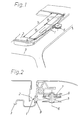
- the sunroof 2 can be moved in the longitudinal direction of the vehicle and in the exemplary embodiment is connected to a power generator which is connected to the body 3 of the vehicle via the power cable 1.
- the electrical connection 4 of the power cable 1 covers the path A for the power consumer.
- a cable reel 5 is arranged on the body 3 approximately in the middle B of the path A, onto which the power cable 1 can be wound.
- the cable reel 5 arranged laterally next to the sunroof 2 on the body 3 can be rotated about an approximately vertical axis of rotation 6, which is formed on one leg of a support element 7 fixed to the body.
- the cable reel 5 is torsionally loaded by a spring 8 for automatically winding the power cable 1 onto the cable reel 5. Due to the arrangement of the cable reel 5 approximately in the middle of the displacement path A between the electrical connection 4 and the cable reel 5, only a short piece of cable is required, which is already held in a stretched position by a weaker spring 8 can. As a result, the power cable 1 cannot carry out any movements which, for example, cause noise by striking the body 3 or the sunroof 2.
- a guide plate 9 is provided on the body side and has a central passage opening which is adapted to the cross section of the power cable 1.
- guide rollers could also be provided, between which the power cable 1 is passed.
- the plane of the guide plate 9 runs parallel to the lateral edge of the sliding roof 2. In order to avoid damage to the power cable 1 when sliding through the passage opening of the guide plate 9, the handling edges of the passage opening are rounded.
- the cable reel is attached to the body.
- this could also be arranged on the sunroof and rotatable about any axis of rotation.
Abstract
Description
- Die Erfindung betrifft eine Vorrichtung zur Führung eines Stromkabels zu einem verschiebbaren Fahrzeugteil, insbesondere zu einem Schiebedach, der im Oberbegriff des Hauptanspruchs angegebenen Art.
- Bewegliche, elektrische oder elektronische Geräte aufnehmende Fahrzeugteile werden mit Strom- oder Meßkabel verbunden, die nicht besonders geführt sind. Dabei besteht die Gefahr, daß die Kabel beschädigt und stromführende Leiter freigelegt werden. Zumindest in einer Endlage des beweglichen Fahrzeugteils hängen die Strom- oder Meßkabel durch und verursachen Geräusche beim Anstoßen an das Fahrzeug. In nahezu gestreckter Lage können die Kabel durch Schwingbewegungen Steckverbindungen an den Kabelenden lösen.
- Es ist deshalb Aufgabe der Erfindung, eine Vorrichtung zur Führung eines Stromkabels zu einem verschiebbaren Fahrzeugteil nach dem Oberbegriff des Hauptanspruchs anzugeben, die das Stromkabel in jeder Lage sicher und weitgehend schwingungsfrei führt und die an unterschiedliche Einbauverhältnisse leicht angepaßt werden kann.
- Gelöst wird diese Aufgabe durch eine drehbare Kabelrolle, die von einer Feder zum Aufrollen des Stromkabels auf die Kabelrolle drehbelastet ist, wobei ein Ende des Stromkabels gegenüber der Lagerung der Kabelrolle ortsfest und die Lagerung so an dem verschiebbaren Fahrzeugteil oder an der Karosserie des Fahrzeugs befestigt ist, daß das Stromkabel etwa in der Mitte des Verschiebeweges des Fahrzeugteils nahezu vollständig auf die Kabelrolle aufgerollt ist. Ein wesentlicher Vorteil ist dabei, daß das Stromkabel immer schwingungsfrei gespannt und soweit wie möglich auf die Kabelrolle vor Beschädigung sicher aufgerollt ist. Außerdem weist das auf die Kabelrolle aufrollbare Kabelstück nur etwa die halbe Länge des Verschiebeweges des Fahrzeugteils auf, so daß sich auch das vollständig abgerollte Stromkabel von einer schwächeren Feder gestreckt halten läßt. Schließlich erfordert das kürzere Stromkabel nur einen geringen Durchmesser der Kabelrolle, so daß sich diese auch bei beengten Einbauverhältnissen leicht unterbringen läßt.
- Es ist zwar durch die DE-PS 24 58 758 eine Einrichtung für die elektrische Versorgung eines beweglichen Verbrauchers bekannt, daß sich diese Einrichtung für bewegliche Fahrzeugteile eignen könnte, ist dieser Schrift jedoch nicht zu entnehmen. Die Einrichtung sieht für einen beweglichen Verbraucheranschluß und für zwei Wickeldorne zum Aufrollen der Stromkabel je einen auf einer Führungsschiene verfahrbaren Wagen vor. Dies erfordert eine aufwendige Bauweise und entlang der Führungsschiene seitliche Freiräume für die Wagen, so daß diese Einrichtung ein hohes Bauvolumen benötigt. Am Umfang der kreisförmig verlaufenden Führungsschiene sind außerdem viele Führungsrollen zur Abstützung der Stromkabel erforderlich.
- Vorteilhafte Ausgestaltungen der Erfindung sind Gegenstand von Unteransprüchen.
- Ein Ausführungsbeispiel der Erfindung wird anhand einer Zeichnung näher erläutert. Es zeigen:
- Fig. 1 eine perspektivische Ansicht der Vorrichtung an einem Schiebedach eines Kraftfahrzeugs und
- Fig. 2 einen Querschnitt durch die Achse der Kabelrolle der Vorrichtung nach Fig. 1.
- In Fig. 1 ist eine Vorrichtung zur Führung eines Stromkabels 1 zu einem Schiebedach 2 eines Fahrzeugs in perspektivischer Ansicht dargestellt. Das Schiebedach 2 ist in Längsrichtung des Fahrzeugs verschiebbar und in dem Ausführungsbeispiel mit einem Stromerzeuger verbunden, der über das Stromkabel 1 mit der Karosserie 3 des Fahrzeugs in Verbindung steht. Zwischen der Schließstellung des Schiebedaches 2 und seiner Öffnungsstellung legt der Elektroanschluß 4 des Stromkabels 1 für den Stromverbraucher den Weg A zurück. Um insbesondere ein Durchhängen oder Schwingen des Stromkabels 1 zu vermeiden ist an der Karosserie 3 etwa in der Mitte B des Weges A eine Kabelrolle 5 angeordnet, auf die das Stromkabel 1 aufwickelbar ist.
- Wie in Fig. 2 dargestellt, ist die seitlich neben dem Schiebedach 2 an der Karosserie 3 angeordnete Kabelrolle 5 um eine etwa vertikale Drehachse 6 drehbar, die an einem Schenkel eines karosseriefesten Stützelements 7 ausgebildet ist. Um das Stromkabel 1 auf Spannung zu halten, ist die Kabelrolle 5 von einer Feder 8 zum selbsttätigen Aufrollen des Stromkabels 1 auf die Kabelrolle 5 drehbelastet. Durch die Anordnung der Kabelrolle 5 etwa in der Mitte des Verschiebeweges A ist zwischen dem Elektroanschluß 4 und der Kabelrolle 5 lediglich ein kurzes Kabelstück erforderlich, das bereits von einer schwächeren Feder 8 in gestreckter Lage gehalten werden kann. Das Stromkabel 1 kann dadurch keine Bewegungen ausführen, die durch Anschlagen an der Karosserie 3 oder an dem Schiebedach 2 beispielsweise Geräusche verursachen. Zur Führung und Abstützung des Stromkabels 1 im Bereich der Kabelrolle 5 ist eine karosserieseitig befestigte Führungsplatte 9 vorgesehen, die eine zentrale, dem Querschnitt des Stromkabels 1 angepaßte Durchtrittsöffnung aufweist. Anstelle der Führungsplatte 9 könnten aber auch Führungsrollen vorgesehen sein, zwischen denen das Stromkabel 1 hindurchgeführt ist. Die Ebene der Führungsplatte 9 verläuft parallel zu dem seitlichen Rand des Schiebedaches 2. Um eine Beschädigung des Stromkabels 1 beim Hindurchgleiten durch die Durchtrittsöffnung der Führungsplatte 9 zu vermeiden, sind die Umgangskanten der Durchtrittsöffnung gerundet.
- Bei dem beschriebenen Ausführungsbeispiel ist die Kabelrolle karosserieseitig befestigt. Ebenso könnte diese aber auch an dem Schiebedach und um eine beliebige Drehachse drehbar angeordnet sein.
Claims (5)
Applications Claiming Priority (2)
| Application Number | Priority Date | Filing Date | Title |
|---|---|---|---|
| DE3614880 | 1986-05-02 | ||
| DE19863614880 DE3614880A1 (de) | 1986-05-02 | 1986-05-02 | Vorrichtung zur fuehrung eines stromkabels zu einem verschiebbaren fahrzeugteil, insbesondere zu einem schiebedach |
Publications (2)
| Publication Number | Publication Date |
|---|---|
| EP0243839A1 true EP0243839A1 (de) | 1987-11-04 |
| EP0243839B1 EP0243839B1 (de) | 1989-10-18 |
Family
ID=6300015
Family Applications (1)
| Application Number | Title | Priority Date | Filing Date |
|---|---|---|---|
| EP87105784A Expired EP0243839B1 (de) | 1986-05-02 | 1987-04-18 | Vorrichtung zur Führung eines Stromkabels zu einem verschiebbaren Fahrzeugteil, insbesondere zu einem Schiebedach |
Country Status (3)
| Country | Link |
|---|---|
| EP (1) | EP0243839B1 (de) |
| DE (2) | DE3614880A1 (de) |
| ES (1) | ES2011279B3 (de) |
Cited By (3)
| Publication number | Priority date | Publication date | Assignee | Title |
|---|---|---|---|---|
| EP0412482A1 (de) * | 1989-08-05 | 1991-02-13 | Alps Electric Co., Ltd. | Schutzvorrichtung für die Kabel einer Steuersäule |
| EP0873912A3 (de) * | 1997-04-23 | 2000-02-02 | DaimlerChrysler AG | Leitungsführung für ein Kraftfahrzeug |
| CN107539240A (zh) * | 2016-06-27 | 2018-01-05 | 矢崎总业株式会社 | 天窗供电结构和天窗单元 |
Families Citing this family (3)
| Publication number | Priority date | Publication date | Assignee | Title |
|---|---|---|---|---|
| DE19650227C1 (de) * | 1996-12-04 | 1997-11-27 | Webasto Karosseriesysteme | Fahrzeugdach mit Kabelverbindung |
| DE10130359A1 (de) | 2001-06-23 | 2003-01-09 | Porsche Ag | Dachanordnung für ein Fahrzeug, insbesondere Kraftfahrzeug |
| DE10331014B3 (de) * | 2003-07-09 | 2005-04-28 | Wincor Nixdorf Int Gmbh | Wickelvorrichtung für ein Kabel, insbesondere für ein Flachkabel |
Family Cites Families (5)
| Publication number | Priority date | Publication date | Assignee | Title |
|---|---|---|---|---|
| US2526256A (en) * | 1947-03-22 | 1950-10-17 | Mihara Kazuo | Conductor reel |
| DE827450C (de) * | 1949-09-04 | 1952-01-10 | Mechanische Werkstaetten W Con | Verbindung elektrischer Kabel zwischen ziehendem und gezogenem Fahrzeug eines Kraftwagenzuges |
| DE1615977A1 (de) * | 1967-07-07 | 1970-09-10 | Heinrich Doepke Fa | Kabelfuehrung in T-Form |
| US3700834A (en) * | 1971-02-10 | 1972-10-24 | Cyril L Schaefer | Electrical cable apparatus |
| DE2517881A1 (de) * | 1975-04-23 | 1976-11-04 | Licentia Gmbh | Kabelaufrollvorrichtung |
-
1986
- 1986-05-02 DE DE19863614880 patent/DE3614880A1/de not_active Withdrawn
-
1987
- 1987-04-18 ES ES87105784T patent/ES2011279B3/es not_active Expired - Lifetime
- 1987-04-18 DE DE8787105784T patent/DE3760794D1/de not_active Expired
- 1987-04-18 EP EP87105784A patent/EP0243839B1/de not_active Expired
Non-Patent Citations (2)
| Title |
|---|
| PATENT ABSTRACTS OF JAPAN, Band 10, Nr. 222 (M-504)[2278], 2. August 1986; & JP-A-61 060 345 (HINO) 28.03.1986 * |
| PATENT ABSTRACTS OF JAPAN, Band 3, Nr. 134 (M-79), 9. November 1979, Seite 96 M 79; & JP-A-54 109 570 (HITACHI) 28.08.1979 * |
Cited By (4)
| Publication number | Priority date | Publication date | Assignee | Title |
|---|---|---|---|---|
| EP0412482A1 (de) * | 1989-08-05 | 1991-02-13 | Alps Electric Co., Ltd. | Schutzvorrichtung für die Kabel einer Steuersäule |
| EP0873912A3 (de) * | 1997-04-23 | 2000-02-02 | DaimlerChrysler AG | Leitungsführung für ein Kraftfahrzeug |
| CN107539240A (zh) * | 2016-06-27 | 2018-01-05 | 矢崎总业株式会社 | 天窗供电结构和天窗单元 |
| US10081233B2 (en) * | 2016-06-27 | 2018-09-25 | Yazaki Corporation | Sunroof feed structure and sunroof unit |
Also Published As
| Publication number | Publication date |
|---|---|
| DE3614880A1 (de) | 1987-11-05 |
| EP0243839B1 (de) | 1989-10-18 |
| ES2011279B3 (es) | 1990-01-01 |
| DE3760794D1 (en) | 1989-11-23 |
Similar Documents
| Publication | Publication Date | Title |
|---|---|---|
| DE3737719C2 (de) | ||
| EP1725788B1 (de) | Schiebet rsystem | |
| DE2806117A1 (de) | Elektrisch betaetigbarer fensterantrieb, insbesondere fuer kraftfahrzeuge | |
| DE3641706A1 (de) | Vorrichtung zur stromuebertragung zwischen zwei relativ zueinander bewegbaren kontaktstellen | |
| DE3232521C2 (de) | Fensterheber für ein Kraftfahrzeug | |
| EP0243839B1 (de) | Vorrichtung zur Führung eines Stromkabels zu einem verschiebbaren Fahrzeugteil, insbesondere zu einem Schiebedach | |
| DE2720936A1 (de) | Kabeleinfuehrung | |
| DE2034514B2 (de) | Einrichtung zur Überführung von elektrischen Kabelsträngen vom Fahrzeugkörper eines Kraftfahrzeuges an bewegliche Teile desselben | |
| DE2629217C2 (de) | Einrichtung zum Bearbeiten von Werkstücken unter Vakuum | |
| DE2623359A1 (de) | Verschlussvorrichtung | |
| DE4028816C2 (de) | ||
| DE3610635A1 (de) | Verbesserte markise in form eines dachs | |
| DE10250150A1 (de) | Gehäuse für Elektroleitungen für Schiebetüren | |
| DE4105865A1 (de) | Vorrichtung zum auf- und abwickeln von behaengen, insbesondere markisenstoffen, rollaeden, gittern oder dergleichen | |
| EP1447515B1 (de) | Rolltor mit verschieblicher Welle | |
| DE2458758A1 (de) | Einrichtung zur aufnahme, laengenanpassung und halterung von leitungen fuer die elektrische versorgung beweglicher verbraucher von einer festen anschlussstelle aus | |
| DE102015205046A1 (de) | Medizinisches Untersuchungsgerät | |
| EP0669690A1 (de) | Bewegliche Kabelverbindung | |
| DE10334137B4 (de) | Stromzuführung zu einer Schiebetür eines Kraftfahrzeuges | |
| DE2036976B2 (de) | Kabeleinfuehrung | |
| DE4001837C2 (de) | ||
| DE2627528A1 (de) | Elektrisch leitende verbindung zwischen einer wand und einer schiebetuer | |
| DE102017200579B3 (de) | Antriebsvorrichtung zur Verlagerung eines formstabilen Funktionsteils | |
| DE2261513C3 (de) | Halterung fur Überspannungsableiter | |
| DE202022101890U1 (de) | Zuführsystem und Rücklaufbremsenmodul für eine Leitung, insbesondere für ein Elektrofahrzeug-Ladekabel |
Legal Events
| Date | Code | Title | Description |
|---|---|---|---|
| PUAI | Public reference made under article 153(3) epc to a published international application that has entered the european phase |
Free format text: ORIGINAL CODE: 0009012 |
|
| AK | Designated contracting states |
Kind code of ref document: A1 Designated state(s): DE ES FR GB IT SE |
|
| 17P | Request for examination filed |
Effective date: 19870929 |
|
| 17Q | First examination report despatched |
Effective date: 19890314 |
|
| GRAA | (expected) grant |
Free format text: ORIGINAL CODE: 0009210 |
|
| AK | Designated contracting states |
Kind code of ref document: B1 Designated state(s): DE ES FR GB IT SE |
|
| ET | Fr: translation filed | ||
| GBT | Gb: translation of ep patent filed (gb section 77(6)(a)/1977) | ||
| REF | Corresponds to: |
Ref document number: 3760794 Country of ref document: DE Date of ref document: 19891123 |
|
| ITF | It: translation for a ep patent filed |
Owner name: STUDIO JAUMANN |
|
| PG25 | Lapsed in a contracting state [announced via postgrant information from national office to epo] |
Ref country code: SE Effective date: 19900419 Ref country code: ES Free format text: LAPSE BECAUSE OF NON-PAYMENT OF DUE FEES Effective date: 19900419 |
|
| PLBE | No opposition filed within time limit |
Free format text: ORIGINAL CODE: 0009261 |
|
| STAA | Information on the status of an ep patent application or granted ep patent |
Free format text: STATUS: NO OPPOSITION FILED WITHIN TIME LIMIT |
|
| 26N | No opposition filed | ||
| PG25 | Lapsed in a contracting state [announced via postgrant information from national office to epo] |
Ref country code: FR Effective date: 19901228 |
|
| PG25 | Lapsed in a contracting state [announced via postgrant information from national office to epo] |
Ref country code: DE Effective date: 19910101 |
|
| REG | Reference to a national code |
Ref country code: FR Ref legal event code: ST |
|
| PG25 | Lapsed in a contracting state [announced via postgrant information from national office to epo] |
Ref country code: GB Effective date: 19910418 |
|
| GBPC | Gb: european patent ceased through non-payment of renewal fee | ||
| EUG | Se: european patent has lapsed |
Ref document number: 87105784.0 Effective date: 19910116 |
|
| REG | Reference to a national code |
Ref country code: ES Ref legal event code: FD2A Effective date: 19990301 |
|
| PG25 | Lapsed in a contracting state [announced via postgrant information from national office to epo] |
Ref country code: IT Free format text: LAPSE BECAUSE OF NON-PAYMENT OF DUE FEES;WARNING: LAPSES OF ITALIAN PATENTS WITH EFFECTIVE DATE BEFORE 2007 MAY HAVE OCCURRED AT ANY TIME BEFORE 2007. THE CORRECT EFFECTIVE DATE MAY BE DIFFERENT FROM THE ONE RECORDED. Effective date: 20050418 |