EP0243594A2 - Plaque, en particulier pour la constitution d'un dispositif de fluidisation et son procédé de fabrication - Google Patents
Plaque, en particulier pour la constitution d'un dispositif de fluidisation et son procédé de fabrication Download PDFInfo
- Publication number
- EP0243594A2 EP0243594A2 EP87102278A EP87102278A EP0243594A2 EP 0243594 A2 EP0243594 A2 EP 0243594A2 EP 87102278 A EP87102278 A EP 87102278A EP 87102278 A EP87102278 A EP 87102278A EP 0243594 A2 EP0243594 A2 EP 0243594A2
- Authority
- EP
- European Patent Office
- Prior art keywords
- wires
- fabric
- plate according
- consist
- monofilament
- Prior art date
- Legal status (The legal status is an assumption and is not a legal conclusion. Google has not performed a legal analysis and makes no representation as to the accuracy of the status listed.)
- Withdrawn
Links
- 238000004519 manufacturing process Methods 0.000 title claims description 11
- 238000010276 construction Methods 0.000 title description 6
- 239000004744 fabric Substances 0.000 claims abstract description 29
- 238000005096 rolling process Methods 0.000 claims description 18
- 239000000463 material Substances 0.000 claims description 8
- 229910052751 metal Inorganic materials 0.000 claims description 8
- 239000002184 metal Substances 0.000 claims description 8
- 238000000034 method Methods 0.000 claims description 5
- 238000009941 weaving Methods 0.000 claims description 5
- 239000000126 substance Substances 0.000 claims 1
- 239000007787 solid Substances 0.000 description 7
- PXHVJJICTQNCMI-UHFFFAOYSA-N Nickel Chemical compound [Ni] PXHVJJICTQNCMI-UHFFFAOYSA-N 0.000 description 4
- 229910000831 Steel Inorganic materials 0.000 description 2
- 235000013339 cereals Nutrition 0.000 description 2
- 238000005243 fluidization Methods 0.000 description 2
- 238000010438 heat treatment Methods 0.000 description 2
- 239000007788 liquid Substances 0.000 description 2
- 229910052759 nickel Inorganic materials 0.000 description 2
- 239000010959 steel Substances 0.000 description 2
- 229910001369 Brass Inorganic materials 0.000 description 1
- RYGMFSIKBFXOCR-UHFFFAOYSA-N Copper Chemical compound [Cu] RYGMFSIKBFXOCR-UHFFFAOYSA-N 0.000 description 1
- 229910000570 Cupronickel Inorganic materials 0.000 description 1
- 239000002253 acid Substances 0.000 description 1
- 150000007513 acids Chemical class 0.000 description 1
- 238000007792 addition Methods 0.000 description 1
- 229910045601 alloy Inorganic materials 0.000 description 1
- 239000000956 alloy Substances 0.000 description 1
- 229910052782 aluminium Inorganic materials 0.000 description 1
- XAGFODPZIPBFFR-UHFFFAOYSA-N aluminium Chemical compound [Al] XAGFODPZIPBFFR-UHFFFAOYSA-N 0.000 description 1
- 239000010951 brass Substances 0.000 description 1
- 239000004568 cement Substances 0.000 description 1
- 229910052802 copper Inorganic materials 0.000 description 1
- 239000010949 copper Substances 0.000 description 1
- YOCUPQPZWBBYIX-UHFFFAOYSA-N copper nickel Chemical compound [Ni].[Cu] YOCUPQPZWBBYIX-UHFFFAOYSA-N 0.000 description 1
- 238000001914 filtration Methods 0.000 description 1
- 239000007789 gas Substances 0.000 description 1
- 239000011344 liquid material Substances 0.000 description 1
- 235000012054 meals Nutrition 0.000 description 1
- 150000002739 metals Chemical class 0.000 description 1
- 239000002245 particle Substances 0.000 description 1
- 230000035699 permeability Effects 0.000 description 1
- 238000005245 sintering Methods 0.000 description 1
- 239000011343 solid material Substances 0.000 description 1
- 229920002994 synthetic fiber Polymers 0.000 description 1
- 238000003466 welding Methods 0.000 description 1
Images
Classifications
-
- B—PERFORMING OPERATIONS; TRANSPORTING
- B65—CONVEYING; PACKING; STORING; HANDLING THIN OR FILAMENTARY MATERIAL
- B65G—TRANSPORT OR STORAGE DEVICES, e.g. CONVEYORS FOR LOADING OR TIPPING, SHOP CONVEYOR SYSTEMS OR PNEUMATIC TUBE CONVEYORS
- B65G53/00—Conveying materials in bulk through troughs, pipes or tubes by floating the materials or by flow of gas, liquid or foam
- B65G53/04—Conveying materials in bulk pneumatically through pipes or tubes; Air slides
- B65G53/16—Gas pressure systems operating with fluidisation of the materials
- B65G53/18—Gas pressure systems operating with fluidisation of the materials through a porous wall
- B65G53/20—Gas pressure systems operating with fluidisation of the materials through a porous wall of an air slide, e.g. a trough
Definitions
- the invention relates to a plate, in particular for the production of fluidizing devices, such as conveyor troughs for dusty goods, consisting of a wire mesh with external wires, internal wires and mesh openings reduced by rolling the fabric. It also relates to a method of making such a plate.
- wire mesh plates are required, which on the one hand have good permeability and on the other hand have a high mechanical strength and a surface that is as smooth as possible, in which, however, the openings for the passage of air or liquid are so small that even the finest dusts or solid components from flooding cannot pass through.
- Powdered solids with very small particle size on the order of a few ⁇ m such as cereal meal, cement or synthetic materials in a very fine-grained form, are transported in trays, which are supplied with air from her finest below by a plurality openings.
- the dust-like solids then behave like a liquid and also flow along a gently sloping channel.
- the bottom and side walls of this gutter must of course have a particularly smooth surface on which the powdery materials can slide easily. So that the dusts cannot pass through the walls and the bottom of the channel, the openings in these areas must be small.
- as many openings as possible have to be provided so that with only slight air overpressure enough air can be blown into the powdery solids to be transported for fluidization.
- tissue plates for the construction of fluidization devices which consist of several thin wire meshes, which are connected by rolling and sintering.
- the resulting product which can be processed like a sheet metal plate, but is porous due to its woven structure, requires many steps to produce and is extremely expensive to manufacture due to its complicated structure. It can also be produced only in limited dimensions, so that larger panels can only be produced by welding smaller individual pieces together.
- Wire mesh is also known for the production of sieves, the mesh openings of which are reduced by rolling the mesh (DE-AS 1 236 182).
- these known rolled sieve fabrics cannot be used as plates for the construction of fluidizing devices, since either the mechanical strength values such as tensile, compressive and flexural tensile strength are not sufficient if the fabrics are made from thin wires, or the mesh size becomes much too large for fluidizing purposes , if thicker wires are used, because openings that are too large then remain in the gussets of the fabric.
- the object of the invention is to provide a material which is simple and inexpensive to manufacture, in particular for the construction of fluidizing devices, in which the mesh size can be reduced to the desired size by simply rolling a wire mesh and at the same time the high strength properties of the sintered fabric plates are at least approximately achieved .
- the outer wires of the fabric are monofilament wires, while the inner wires consist of wire bundles running essentially in a straight line.
- a “straight wire bundle” is understood to mean a large number of thin wires that pass through the fabric without cranking.
- the thin individual wires can run parallel to one another, but the wires are preferably stranded or twisted together.
- the total thickness of the inner wire bundle is at least twice as large as the diameter of the thin outer individual wires.
- Metal wires are usually used for the fabric. However, it is also possible to use for the outer monofilament wires or for the inner wire bundles or for both plastic wires.
- the plate according to the invention After the wire mesh has been rolled, the plate according to the invention has approximately the appearance and strength of a porous sheet and can be processed like such. Since the inner wires consist of a bundle of several thin wires running in the longitudinal direction, they can be in the bond during rolling Lich shift and fill the gusset at the intersection of the outer wires, so that there is a very dense fabric that is impermeable even to the finest dusts, but air can pass through in sufficient quantity and in a very finely divided form. As a result of the rolling process, the surface of the fabric plate becomes very smooth and the structure is solidified in such a way that the wire mesh takes on the character of a sheet which can also be manufactured and processed in large dimensions.
- the wires of the inner wire bundles consist of a different material than the outer, monofilament wires.
- a softer metal for example copper, brass, nickel or aluminum, for the wires of the inner wire bundles than for the outer, monofilament wires, which should consist of steel wires to achieve the greatest possible surface hardness.
- the material is to be used at higher temperatures, it is advantageous to make the wires from a material with low thermal expansion, e.g. to produce from a copper-nickel alloy.
- the inner wire bundles can be the warp wires of the fabric. However, it is preferably the weft wires that are designed as internal wire bundles. In order to achieve the smoothest possible surface, it is advisable to provide a twill weave.
- the fabric When manufacturing a plate according to the invention, it is expedient to proceed so that after weaving or monofilament wires and wire bundles, the fabric in the longitudinal direction tion of its external, monofilament wires is rolled. Depending on the type of wire material used, the fabric can also be rolled in several passes between pairs of rollers. In order to eliminate material hardening by rolling, it is expedient to give the fabric a heat treatment after the rolling and, if appropriate, also between the individual rolling processes and, for example, to anneal it.
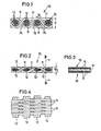
- 10 denotes a woven wire plate with a twill weave, the outer wires 11 of which are monofilament metal wires which form the chain of the fabric.
- the outer wires 11 are monofilament steel wires
- the wire bundles or strands 12 consist of thin nickel wires.
- the wire mesh 10 After weaving, the wire mesh 10 has the shape shown in FIG. 1. Thereafter, the fabric is rolled in the longitudinal direction 14 of its outer monofilament wires 11 in one or more passes between pairs of rolls and thereby brought to less than half of its original thickness d , so that it assumes the longitudinal section shown in FIG. 2. It can be seen that the fabric is only slightly elongated due to the rolling process and that the initially round wire bundles take on an oval shape in cross section, the individual wires 13 deforming in cross section and the open gussets 15 still present in the fabric immediately after the weaving process Fill in the crossing points between the outer wires. Since these outer wires not only intersect in longitudinal section (Fig. 2), but also run one above the other in plan (Fig.
- the finished rolled fabric plate has no opening from top to bottom through which fine-grained solids could fall.
- the surfaces 16 of the closely spaced outer wires 11 are flattened by the rolling process and form a practically closed surface which has only very fine gaps and holes through which air or other gases can pass, but which does not allow any solids to fall through above the required grain size .
- the size of the openings can be influenced by the rolling.
- the wire mesh plate rolled in this way can then be subjected to a heat treatment in order to remove internal stresses which were caused by the weaving and rolling process.
- the construction according to the invention gives the wire mesh plate a high strength after the rolling process and approximately the rigidity and properties of a sheet metal plate, so that it can be used with particular advantage for the production of channels, pipes and containers for fluidizing powdery solids.
- the internal and external wires or wire bundles are not welded or sintered to one another, it is possible to process the fabric like a sheet metal plate and to weld it to one another or to other sheets.
- the invention is not limited to the exemplary embodiment shown and described, but several changes and additions are possible without leaving the scope of the invention.
- the warp wires as a straight wire bundle or to provide other weaves such as a five-shaft weave.
- the wires in particular the individual wires of the wire bundles, can also be plastic wires. The use of plastic wires is particularly recommended when the wire mesh according to the invention comes into contact with acids which strongly attack metals.
Landscapes
- Engineering & Computer Science (AREA)
- Mechanical Engineering (AREA)
- Woven Fabrics (AREA)
- Cell Separators (AREA)
- Air Bags (AREA)
- Preparing Plates And Mask In Photomechanical Process (AREA)
- Filtering Materials (AREA)
- Physical Or Chemical Processes And Apparatus (AREA)
- Reciprocating Pumps (AREA)
Applications Claiming Priority (2)
| Application Number | Priority Date | Filing Date | Title |
|---|---|---|---|
| DE3614680 | 1986-04-30 | ||
| DE19863614680 DE3614680A1 (de) | 1986-04-30 | 1986-04-30 | Platte, insbesondere zum herstellen von fluidisiereinrichtungen und verfahren zu ihrer herstellung |
Publications (2)
| Publication Number | Publication Date |
|---|---|
| EP0243594A2 true EP0243594A2 (fr) | 1987-11-04 |
| EP0243594A3 EP0243594A3 (fr) | 1988-08-03 |
Family
ID=6299892
Family Applications (1)
| Application Number | Title | Priority Date | Filing Date |
|---|---|---|---|
| EP87102278A Withdrawn EP0243594A3 (fr) | 1986-04-30 | 1987-02-18 | Plaque, en particulier pour la constitution d'un dispositif de fluidisation et son procédé de fabrication |
Country Status (3)
| Country | Link |
|---|---|
| EP (1) | EP0243594A3 (fr) |
| DE (1) | DE3614680A1 (fr) |
| NO (1) | NO871815L (fr) |
Cited By (1)
| Publication number | Priority date | Publication date | Assignee | Title |
|---|---|---|---|---|
| EP1816095A1 (fr) * | 2006-02-07 | 2007-08-08 | IBAU Hamburg Ingenieurgesellschaft | Dispositif de transport pneumatique de matières pulvérulentes |
Family Cites Families (3)
| Publication number | Priority date | Publication date | Assignee | Title |
|---|---|---|---|---|
| DE934696C (de) * | 1952-11-25 | 1955-11-03 | Carl Haver & Ed Boecker | Poroese Unterlage fuer pneumatische Foerderrinnen |
| DE1236182B (de) * | 1965-07-30 | 1967-03-09 | Becker & Van Huellen | Siebgeflecht fuer in Pressen zu plattenartigen Gebilden zu formendes Pressgut, vorzugsweise Spanplatten |
| DE1961050B2 (de) * | 1969-12-05 | 1979-09-20 | Duerener Metalltuch Schoeller, Hoesch & Co, 5160 Dueren | Metalldrahtgewebe |
-
1986
- 1986-04-30 DE DE19863614680 patent/DE3614680A1/de not_active Withdrawn
-
1987
- 1987-02-18 EP EP87102278A patent/EP0243594A3/fr not_active Withdrawn
- 1987-04-30 NO NO871815A patent/NO871815L/no unknown
Cited By (2)
| Publication number | Priority date | Publication date | Assignee | Title |
|---|---|---|---|---|
| EP1816095A1 (fr) * | 2006-02-07 | 2007-08-08 | IBAU Hamburg Ingenieurgesellschaft | Dispositif de transport pneumatique de matières pulvérulentes |
| US7329071B2 (en) | 2006-02-07 | 2008-02-12 | Ibau Hamburg Ingenieurgesellschaft Industriebau Mbh | Device for the pneumatic conveying of particulate and powdery bulk material |
Also Published As
| Publication number | Publication date |
|---|---|
| EP0243594A3 (fr) | 1988-08-03 |
| NO871815L (no) | 1987-11-02 |
| DE3614680A1 (de) | 1987-11-05 |
| NO871815D0 (no) | 1987-04-30 |
Similar Documents
| Publication | Publication Date | Title |
|---|---|---|
| DE1924449C3 (de) | Gas- und flüssigkeitsdurchlässiger Drahtgewirk-Verbundkörper von mehrschichtigem Aufbau und Verfahren zur Herstellung desselben | |
| DE3686638T2 (de) | Verfahren zur herstellung von titan-nickel-legierungen. | |
| DE2942815C2 (de) | Metallblechschichtkörper | |
| DE4201791A1 (de) | Flachrohre zum einbau in einen flachrohrwaermetauscher und verfahren zum vereinzeln der flachrohre | |
| EP0505832A1 (fr) | Corps filtrant ou catalytique | |
| DE3249345T1 (de) | Sicherheitsstange | |
| DE4424936A1 (de) | Pulpepreßform und Herstellungsverfahren für diese und geformter Pulpeartikel und Herstellungsverfahren für diesen | |
| EP1421230A2 (fr) | Fabrication de tissus de coussins gonflables de securite | |
| DE2517857C2 (de) | Vorrichtung zum Abscheiden magnetisierbarer Teilchen aus einer Suspension | |
| EP1397191B1 (fr) | Filtre a particules de gaz d'echappement en metal fritte | |
| EP0243594A2 (fr) | Plaque, en particulier pour la constitution d'un dispositif de fluidisation et son procédé de fabrication | |
| DE3013560A1 (de) | Hochofen-korsettkuehlvorrichtung | |
| DE102017213515B4 (de) | Wabenstruktur-Formwerkzeug | |
| DE4101919A1 (de) | Verfahren zur herstellung von platten aus duktilem metall und dessen anwendungen | |
| DE1115699B (de) | Verfahren zum Herstellen feinporiger Lochbleche aus feinen metallischen Drahtgeflechten | |
| DE2933263A1 (de) | Doppelgewebebahn | |
| DE10257962C5 (de) | Leichtbauteil aus Hohlkugeln | |
| EP1418261A1 (fr) | Tissu de fils métalliques | |
| DE2114852B2 (de) | Verfahren zum Herstellen eines Metallkörpers | |
| DE10301037A1 (de) | Abgaspartikelfilter aus Sintermetall | |
| DE3132998C2 (de) | Filterelement für Schlauchfilter | |
| DE3445496C2 (de) | Fördergurt | |
| DE2057855A1 (de) | Verfahren zum Herstellen von Laengen eines Mehrschichtverbundes aus UEbergangseinsatzmaterial | |
| DE1753524C (de) | Webedraht aus Kunststoff fur endlose Papiermaschinensiebe und kontinuierliches Strangpreßverfahren zum Herstellen des We bedrahtes | |
| DE102008029083A1 (de) | Filtervorrichtung und Verfahren zur Herstellung einer Filtervorrichtung |
Legal Events
| Date | Code | Title | Description |
|---|---|---|---|
| PUAI | Public reference made under article 153(3) epc to a published international application that has entered the european phase |
Free format text: ORIGINAL CODE: 0009012 |
|
| AK | Designated contracting states |
Kind code of ref document: A2 Designated state(s): CH DE ES FR GB IT LI NL |
|
| 17P | Request for examination filed |
Effective date: 19880122 |
|
| PUAL | Search report despatched |
Free format text: ORIGINAL CODE: 0009013 |
|
| AK | Designated contracting states |
Kind code of ref document: A3 Designated state(s): CH DE ES FR GB IT LI NL |
|
| 17Q | First examination report despatched |
Effective date: 19881104 |
|
| STAA | Information on the status of an ep patent application or granted ep patent |
Free format text: STATUS: THE APPLICATION HAS BEEN WITHDRAWN |
|
| 18W | Application withdrawn |
Withdrawal date: 19900912 |
|
| RIN1 | Information on inventor provided before grant (corrected) |
Inventor name: SCHOELLER, JOCHEN, DIPL.-ING. |