EP0243594A2 - Plate, especially for the construction of a fluidizing device, and method of manufacturing it - Google Patents
Plate, especially for the construction of a fluidizing device, and method of manufacturing it Download PDFInfo
- Publication number
- EP0243594A2 EP0243594A2 EP87102278A EP87102278A EP0243594A2 EP 0243594 A2 EP0243594 A2 EP 0243594A2 EP 87102278 A EP87102278 A EP 87102278A EP 87102278 A EP87102278 A EP 87102278A EP 0243594 A2 EP0243594 A2 EP 0243594A2
- Authority
- EP
- European Patent Office
- Prior art keywords
- wires
- fabric
- plate according
- consist
- monofilament
- Prior art date
- Legal status (The legal status is an assumption and is not a legal conclusion. Google has not performed a legal analysis and makes no representation as to the accuracy of the status listed.)
- Withdrawn
Links
- 238000004519 manufacturing process Methods 0.000 title claims description 11
- 238000010276 construction Methods 0.000 title description 6
- 239000004744 fabric Substances 0.000 claims abstract description 29
- 238000005096 rolling process Methods 0.000 claims description 18
- 239000000463 material Substances 0.000 claims description 8
- 229910052751 metal Inorganic materials 0.000 claims description 8
- 239000002184 metal Substances 0.000 claims description 8
- 238000000034 method Methods 0.000 claims description 5
- 238000009941 weaving Methods 0.000 claims description 5
- 239000000126 substance Substances 0.000 claims 1
- 239000007787 solid Substances 0.000 description 7
- PXHVJJICTQNCMI-UHFFFAOYSA-N Nickel Chemical compound [Ni] PXHVJJICTQNCMI-UHFFFAOYSA-N 0.000 description 4
- 229910000831 Steel Inorganic materials 0.000 description 2
- 235000013339 cereals Nutrition 0.000 description 2
- 238000005243 fluidization Methods 0.000 description 2
- 238000010438 heat treatment Methods 0.000 description 2
- 239000007788 liquid Substances 0.000 description 2
- 229910052759 nickel Inorganic materials 0.000 description 2
- 239000010959 steel Substances 0.000 description 2
- 229910001369 Brass Inorganic materials 0.000 description 1
- RYGMFSIKBFXOCR-UHFFFAOYSA-N Copper Chemical compound [Cu] RYGMFSIKBFXOCR-UHFFFAOYSA-N 0.000 description 1
- 229910000570 Cupronickel Inorganic materials 0.000 description 1
- 239000002253 acid Substances 0.000 description 1
- 150000007513 acids Chemical class 0.000 description 1
- 238000007792 addition Methods 0.000 description 1
- 229910045601 alloy Inorganic materials 0.000 description 1
- 239000000956 alloy Substances 0.000 description 1
- 229910052782 aluminium Inorganic materials 0.000 description 1
- XAGFODPZIPBFFR-UHFFFAOYSA-N aluminium Chemical compound [Al] XAGFODPZIPBFFR-UHFFFAOYSA-N 0.000 description 1
- 239000010951 brass Substances 0.000 description 1
- 239000004568 cement Substances 0.000 description 1
- 229910052802 copper Inorganic materials 0.000 description 1
- 239000010949 copper Substances 0.000 description 1
- YOCUPQPZWBBYIX-UHFFFAOYSA-N copper nickel Chemical compound [Ni].[Cu] YOCUPQPZWBBYIX-UHFFFAOYSA-N 0.000 description 1
- 238000001914 filtration Methods 0.000 description 1
- 239000007789 gas Substances 0.000 description 1
- 239000011344 liquid material Substances 0.000 description 1
- 235000012054 meals Nutrition 0.000 description 1
- 150000002739 metals Chemical class 0.000 description 1
- 239000002245 particle Substances 0.000 description 1
- 230000035699 permeability Effects 0.000 description 1
- 238000005245 sintering Methods 0.000 description 1
- 239000011343 solid material Substances 0.000 description 1
- 229920002994 synthetic fiber Polymers 0.000 description 1
- 238000003466 welding Methods 0.000 description 1
Images
Classifications
-
- B—PERFORMING OPERATIONS; TRANSPORTING
- B65—CONVEYING; PACKING; STORING; HANDLING THIN OR FILAMENTARY MATERIAL
- B65G—TRANSPORT OR STORAGE DEVICES, e.g. CONVEYORS FOR LOADING OR TIPPING, SHOP CONVEYOR SYSTEMS OR PNEUMATIC TUBE CONVEYORS
- B65G53/00—Conveying materials in bulk through troughs, pipes or tubes by floating the materials or by flow of gas, liquid or foam
- B65G53/04—Conveying materials in bulk pneumatically through pipes or tubes; Air slides
- B65G53/16—Gas pressure systems operating with fluidisation of the materials
- B65G53/18—Gas pressure systems operating with fluidisation of the materials through a porous wall
- B65G53/20—Gas pressure systems operating with fluidisation of the materials through a porous wall of an air slide, e.g. a trough
Definitions
- the invention relates to a plate, in particular for the production of fluidizing devices, such as conveyor troughs for dusty goods, consisting of a wire mesh with external wires, internal wires and mesh openings reduced by rolling the fabric. It also relates to a method of making such a plate.
- wire mesh plates are required, which on the one hand have good permeability and on the other hand have a high mechanical strength and a surface that is as smooth as possible, in which, however, the openings for the passage of air or liquid are so small that even the finest dusts or solid components from flooding cannot pass through.
- Powdered solids with very small particle size on the order of a few ⁇ m such as cereal meal, cement or synthetic materials in a very fine-grained form, are transported in trays, which are supplied with air from her finest below by a plurality openings.
- the dust-like solids then behave like a liquid and also flow along a gently sloping channel.
- the bottom and side walls of this gutter must of course have a particularly smooth surface on which the powdery materials can slide easily. So that the dusts cannot pass through the walls and the bottom of the channel, the openings in these areas must be small.
- as many openings as possible have to be provided so that with only slight air overpressure enough air can be blown into the powdery solids to be transported for fluidization.
- tissue plates for the construction of fluidization devices which consist of several thin wire meshes, which are connected by rolling and sintering.
- the resulting product which can be processed like a sheet metal plate, but is porous due to its woven structure, requires many steps to produce and is extremely expensive to manufacture due to its complicated structure. It can also be produced only in limited dimensions, so that larger panels can only be produced by welding smaller individual pieces together.
- Wire mesh is also known for the production of sieves, the mesh openings of which are reduced by rolling the mesh (DE-AS 1 236 182).
- these known rolled sieve fabrics cannot be used as plates for the construction of fluidizing devices, since either the mechanical strength values such as tensile, compressive and flexural tensile strength are not sufficient if the fabrics are made from thin wires, or the mesh size becomes much too large for fluidizing purposes , if thicker wires are used, because openings that are too large then remain in the gussets of the fabric.
- the object of the invention is to provide a material which is simple and inexpensive to manufacture, in particular for the construction of fluidizing devices, in which the mesh size can be reduced to the desired size by simply rolling a wire mesh and at the same time the high strength properties of the sintered fabric plates are at least approximately achieved .
- the outer wires of the fabric are monofilament wires, while the inner wires consist of wire bundles running essentially in a straight line.
- a “straight wire bundle” is understood to mean a large number of thin wires that pass through the fabric without cranking.
- the thin individual wires can run parallel to one another, but the wires are preferably stranded or twisted together.
- the total thickness of the inner wire bundle is at least twice as large as the diameter of the thin outer individual wires.
- Metal wires are usually used for the fabric. However, it is also possible to use for the outer monofilament wires or for the inner wire bundles or for both plastic wires.
- the plate according to the invention After the wire mesh has been rolled, the plate according to the invention has approximately the appearance and strength of a porous sheet and can be processed like such. Since the inner wires consist of a bundle of several thin wires running in the longitudinal direction, they can be in the bond during rolling Lich shift and fill the gusset at the intersection of the outer wires, so that there is a very dense fabric that is impermeable even to the finest dusts, but air can pass through in sufficient quantity and in a very finely divided form. As a result of the rolling process, the surface of the fabric plate becomes very smooth and the structure is solidified in such a way that the wire mesh takes on the character of a sheet which can also be manufactured and processed in large dimensions.
- the wires of the inner wire bundles consist of a different material than the outer, monofilament wires.
- a softer metal for example copper, brass, nickel or aluminum, for the wires of the inner wire bundles than for the outer, monofilament wires, which should consist of steel wires to achieve the greatest possible surface hardness.
- the material is to be used at higher temperatures, it is advantageous to make the wires from a material with low thermal expansion, e.g. to produce from a copper-nickel alloy.
- the inner wire bundles can be the warp wires of the fabric. However, it is preferably the weft wires that are designed as internal wire bundles. In order to achieve the smoothest possible surface, it is advisable to provide a twill weave.
- the fabric When manufacturing a plate according to the invention, it is expedient to proceed so that after weaving or monofilament wires and wire bundles, the fabric in the longitudinal direction tion of its external, monofilament wires is rolled. Depending on the type of wire material used, the fabric can also be rolled in several passes between pairs of rollers. In order to eliminate material hardening by rolling, it is expedient to give the fabric a heat treatment after the rolling and, if appropriate, also between the individual rolling processes and, for example, to anneal it.
- 10 denotes a woven wire plate with a twill weave, the outer wires 11 of which are monofilament metal wires which form the chain of the fabric.
- the outer wires 11 are monofilament steel wires
- the wire bundles or strands 12 consist of thin nickel wires.
- the wire mesh 10 After weaving, the wire mesh 10 has the shape shown in FIG. 1. Thereafter, the fabric is rolled in the longitudinal direction 14 of its outer monofilament wires 11 in one or more passes between pairs of rolls and thereby brought to less than half of its original thickness d , so that it assumes the longitudinal section shown in FIG. 2. It can be seen that the fabric is only slightly elongated due to the rolling process and that the initially round wire bundles take on an oval shape in cross section, the individual wires 13 deforming in cross section and the open gussets 15 still present in the fabric immediately after the weaving process Fill in the crossing points between the outer wires. Since these outer wires not only intersect in longitudinal section (Fig. 2), but also run one above the other in plan (Fig.
- the finished rolled fabric plate has no opening from top to bottom through which fine-grained solids could fall.
- the surfaces 16 of the closely spaced outer wires 11 are flattened by the rolling process and form a practically closed surface which has only very fine gaps and holes through which air or other gases can pass, but which does not allow any solids to fall through above the required grain size .
- the size of the openings can be influenced by the rolling.
- the wire mesh plate rolled in this way can then be subjected to a heat treatment in order to remove internal stresses which were caused by the weaving and rolling process.
- the construction according to the invention gives the wire mesh plate a high strength after the rolling process and approximately the rigidity and properties of a sheet metal plate, so that it can be used with particular advantage for the production of channels, pipes and containers for fluidizing powdery solids.
- the internal and external wires or wire bundles are not welded or sintered to one another, it is possible to process the fabric like a sheet metal plate and to weld it to one another or to other sheets.
- the invention is not limited to the exemplary embodiment shown and described, but several changes and additions are possible without leaving the scope of the invention.
- the warp wires as a straight wire bundle or to provide other weaves such as a five-shaft weave.
- the wires in particular the individual wires of the wire bundles, can also be plastic wires. The use of plastic wires is particularly recommended when the wire mesh according to the invention comes into contact with acids which strongly attack metals.
Landscapes
- Engineering & Computer Science (AREA)
- Mechanical Engineering (AREA)
- Woven Fabrics (AREA)
- Cell Separators (AREA)
- Air Bags (AREA)
- Preparing Plates And Mask In Photomechanical Process (AREA)
- Filtering Materials (AREA)
- Physical Or Chemical Processes And Apparatus (AREA)
- Reciprocating Pumps (AREA)
Abstract
Description
Die Erfindung betrifft eine Platte, insbesondere zum Herstellen von Fluidisiereinrichtungen, wie Förderrinnen für staubförmige Güter, bestehend aus einem Drahtgewebe mit außenliegenden Drähten, innenliegenden Drähten und durch Walzen des Gewebes verkleinerten Maschenöffnungen. Sie hat auch ein Verfahren zum Herstellen einer solchen Platte zum Gegenstand.The invention relates to a plate, in particular for the production of fluidizing devices, such as conveyor troughs for dusty goods, consisting of a wire mesh with external wires, internal wires and mesh openings reduced by rolling the fabric. It also relates to a method of making such a plate.
Für den Bau von Behältnissen und Anlagen zum Auflockern und Fördern von fluidisierten, pulverförmigen festen Stoffen, aber auch zum Filtrieren oder Zentrifugieren von flüssigen Stoffen, werden Drahtgewebeplatten benötigt, die einerseits eine gute Durchlässigkeit und andererseits eine hohe mechanische Festigkeit und eine möglichst glatte Oberfläche haben, bei denen jedoch die Öffnungen für den Luft- oder Flüssigkeitsdurchlaß so klein sind, daß auch feinste Stäube oder Festbestandteile von Aufschwemmungen nicht hindurchtreten können.For the construction of containers and systems for loosening and conveying fluidized, powdery solid materials, but also for filtering or centrifuging liquid materials, wire mesh plates are required, which on the one hand have good permeability and on the other hand have a high mechanical strength and a surface that is as smooth as possible, in which, however, the openings for the passage of air or liquid are so small that even the finest dusts or solid components from flooding cannot pass through.
Staubförmige Feststoffe mit sehr kleiner Partikelgröße in der Größenordnung von wenigen µ m, wie Getreidemehl, Zement oder auch Kunststoffe in sehr feinkörniger Form, werden in Rinnen transportiert, denen von unten her durch eine Vielzahl feinster Öffnungen Luft zugeführt wird. Die staubförmigen Feststoffe verhalten sich dann wie eine Flüssigkeit und fließen auch eine nur flachgeneigte Rinne entlang. Boden und Seitenwände dieser Rinne müssen hierbei natürlich eine besonders glatte Oberfläche haben, auf der die pulverförmigen Stoffe leicht entlanggleiten können. Damit die Stäube nicht durch die Wände und den Boden der Rinne hindurchtreten können, müssen die Öffnungen in diesen Flächen klein sein. Andererseits müssen aber möglichst viele Öffnungen vorhanden sein, damit bei nur geringem Luftüberdruck genügend Luft zum Fluidisieren in die zu transportierenden pulverförmigen Feststoffe eingeblasen werden kann.Powdered solids with very small particle size on the order of a few μ m, such as cereal meal, cement or synthetic materials in a very fine-grained form, are transported in trays, which are supplied with air from her finest below by a plurality openings. The dust-like solids then behave like a liquid and also flow along a gently sloping channel. The bottom and side walls of this gutter must of course have a particularly smooth surface on which the powdery materials can slide easily. So that the dusts cannot pass through the walls and the bottom of the channel, the openings in these areas must be small. On the other hand, however, as many openings as possible have to be provided so that with only slight air overpressure enough air can be blown into the powdery solids to be transported for fluidization.
Es gibt bereits für den Bau von Fluidisierungseinrichtungen Gewebeplatten, die aus mehreren, dünnen Drahtgeweben bestehen, die durch Walzen und Sintern miteinander verbunden sind. Das hierdurch entstandene Erzeugnis, das wie eine Blechplatte bearbeitet werden kann, aber infolge seiner Gewebestruktur porös ist, erfordert zu seiner Herstellung viele Arbeitsgänge und ist infolge seines komplizierten Aufbaus außerordentlich teuer in der Herstellung. Es ist auch nur in begrenzten Abmessungen herstellbar, so daß größere Tafeln nur durch Zusammenschweißen kleinerer Einzelstücke gefertigt werden können.There are already tissue plates for the construction of fluidization devices, which consist of several thin wire meshes, which are connected by rolling and sintering. The resulting product, which can be processed like a sheet metal plate, but is porous due to its woven structure, requires many steps to produce and is extremely expensive to manufacture due to its complicated structure. It can also be produced only in limited dimensions, so that larger panels can only be produced by welding smaller individual pieces together.
Zur Herstellung von Sieben sind auch schon Drahtgewebe bekannt, deren Maschenöffnungen durch Walzen des Gewebes verkleinert sind (DE-AS 1 236 182). Diese bekannten gewalzten Siebgewebe sind jedoch als Platten für den Bau von Fluidisiereinrichtungen nicht verwendbar, da entweder die mechanischen Festigkeitswerte wie Zug-, Druck- und Biegezugfestigkeit nicht ausreichen, wenn die Gewebe aus dünnen Drähten hergestellt sind, oder die Maschenweite für Fluidisierungszwecke viel zu groß wird, wenn dickere Drähte verwendet werden, da in den Zwickeln des Gewebes dann zu große Öffnungen verbleiben.Wire mesh is also known for the production of sieves, the mesh openings of which are reduced by rolling the mesh (DE-AS 1 236 182). However, these known rolled sieve fabrics cannot be used as plates for the construction of fluidizing devices, since either the mechanical strength values such as tensile, compressive and flexural tensile strength are not sufficient if the fabrics are made from thin wires, or the mesh size becomes much too large for fluidizing purposes , if thicker wires are used, because openings that are too large then remain in the gussets of the fabric.
Aufgabe der Erfindung ist es, ein einfach und billig herzustellendes Material insbesondere für den Bau von Fluidisiereinrichtungen zu schaffen, bei dem durch einfaches Walzen eines Drahtgewebes dessen Maschenweite auf die gewünschte Größe verkleinert werden kann und gleichzeitig gleichwohl die hohen Festigkeitseigenschaften der gesinterten Gewebeplatten wenigstens annähernd erreicht werden.The object of the invention is to provide a material which is simple and inexpensive to manufacture, in particular for the construction of fluidizing devices, in which the mesh size can be reduced to the desired size by simply rolling a wire mesh and at the same time the high strength properties of the sintered fabric plates are at least approximately achieved .
Diese Aufgabe wird mit der Erfindung dadurch gelöst, daß die außenliegenden Drähte des Gewebes monofile Drähte sind, während die innenliegenden Drähte aus im wesentlichen geradlinig durchlaufenden Drahtbündeln bestehen.This object is achieved with the invention in that the outer wires of the fabric are monofilament wires, while the inner wires consist of wire bundles running essentially in a straight line.
Unter "geradlinig durchlaufenden Drahtbündeln" wird eine Vielzahl von im Gewebe ungekröpft durchlaufenden dünnen Drähten verstanden. Hierbei können die dünnen Einzeldrähte parallel zueinander verlaufen, vorzugsweise werden die Drähte jedoch miteinander verseilt oder drilliert. Um die erforderlichen mechanischen Festigkeitswerte zu erreichen, ist es zweckmäßig, wenn die Gesamtdicke des innenliegenden Drahtbündels mindestens zweimal so groß ist wie der Durchmesser der dünnen außenliegenden Einzeldrähte.A “straight wire bundle” is understood to mean a large number of thin wires that pass through the fabric without cranking. In this case, the thin individual wires can run parallel to one another, but the wires are preferably stranded or twisted together. In order to achieve the required mechanical strength values, it is expedient if the total thickness of the inner wire bundle is at least twice as large as the diameter of the thin outer individual wires.
Für das Gewebe werden in der Regel Metalldrähte verwendet. Es ist jedoch auch möglich, für die außenliegenden monofilen Drähte oder für die innenliegenden Drahtbündel oder für beide Kunststoffdrähte zu verwenden.Metal wires are usually used for the fabric. However, it is also possible to use for the outer monofilament wires or for the inner wire bundles or for both plastic wires.
Die Platte nach der Erfindung erlangt nach dem Walzen des Drahtgewebes annähernd das Aussehen und die Festigkeit eines porösen Bleches und kann wie ein solches bearbeitet werden. Da die innenliegenden Drähte aus einem Bündel von mehreren, dünnen, in Längsrichtung durchlaufenden Drähten bestehen, können sie sich in der Bindung beim Walzen seit lich verschieben und die Zwickel an den Kreuzungspunkten der außenliegenden Drähte ausfüllen, so daß sich ein sehr dichtes Gewebe ergibt, das auch für feinste Stäube undurchlässig ist, aber Luft in ausreichender Menge und in sehr fein verteilter Form hindurchtreten läßt. Durch den Walzprozeß wird die Oberfläche der Gewebeplatte sehr glatt und die Struktur so verfestigt, daß das Drahtgewebe den Charakter eines Bleches annimmt, das auch in großen Abmessungen gefertigt und verarbeitet werden kann.After the wire mesh has been rolled, the plate according to the invention has approximately the appearance and strength of a porous sheet and can be processed like such. Since the inner wires consist of a bundle of several thin wires running in the longitudinal direction, they can be in the bond during rolling Lich shift and fill the gusset at the intersection of the outer wires, so that there is a very dense fabric that is impermeable even to the finest dusts, but air can pass through in sufficient quantity and in a very finely divided form. As a result of the rolling process, the surface of the fabric plate becomes very smooth and the structure is solidified in such a way that the wire mesh takes on the character of a sheet which can also be manufactured and processed in large dimensions.
Besonders vorteilhaft ist es, wenn die Drähte der innenliegenden Drahtbündel aus einem anderen Material bestehen als die außenliegenden, monofilen Drähte. Insbesondere kann es zweckmäßig sein, für die Drähte der innenliegenden Drahtbündel ein weicheres Metall, beispielsweise Kupfer, Messing, Nickel oder Aluminium zu verwenden als für die außenliegenden, monofilen Drähte, die zur Erzielung einer möglichst großen Oberflächenhärte möglichst aus Stahldrähten bestehen sollten.It is particularly advantageous if the wires of the inner wire bundles consist of a different material than the outer, monofilament wires. In particular, it can be expedient to use a softer metal, for example copper, brass, nickel or aluminum, for the wires of the inner wire bundles than for the outer, monofilament wires, which should consist of steel wires to achieve the greatest possible surface hardness.
Falls das Material bei höheren Temperaturen eingesetzt werden soll, ist es vorteilhaft, die Drähte aus einem Material mit geringer Wärmedehnung z.B. aus einer Kupfer-Nickel-Legierung herzustellen.If the material is to be used at higher temperatures, it is advantageous to make the wires from a material with low thermal expansion, e.g. to produce from a copper-nickel alloy.
Die innenliegenden Drahtbündel können die Kettdrähte des Gewebes sein. Vorzugsweise sind es jedoch die Schußdrähte, die als innenliegende Drahtbündel ausgeführt werden. Um eine möglichst glatte Oberfläche zu erzielen, ist es zweckmäßig, eine Köperbindung vorzusehen.The inner wire bundles can be the warp wires of the fabric. However, it is preferably the weft wires that are designed as internal wire bundles. In order to achieve the smoothest possible surface, it is advisable to provide a twill weave.
Beim Herstellen einer Platte nach der Erfindung wird zweckmäßig so vorgegangen, daß nach dem Verweben oder monofilen Drähte und Drahtbündel das Gewebe in Längsrich tung seiner außenliegenden, monofilen Drähte gewalzt wird. Je nach Art des verwendeten Drahtmaterials kann das Gewebe auch in mehreren Durchgängen zwischen Walzenpaaren gewalzt werden. Um Materialverfestigungen durch das Walzen zu beseitigen, ist es zweckmäßig, dem Gewebe nach dem Walzen und gegebenenfalls auch zwischen den einzelnen Walzvorgängen eine Wärmebehandlung zuteil werden zu lassen und beispielsweise zu glühen.When manufacturing a plate according to the invention, it is expedient to proceed so that after weaving or monofilament wires and wire bundles, the fabric in the longitudinal direction tion of its external, monofilament wires is rolled. Depending on the type of wire material used, the fabric can also be rolled in several passes between pairs of rollers. In order to eliminate material hardening by rolling, it is expedient to give the fabric a heat treatment after the rolling and, if appropriate, also between the individual rolling processes and, for example, to anneal it.
Weitere Merkmale und Vorteile der Erfindung ergeben sich aus der nachfolgenden Beschreibung und der Zeichnung, in der eine bevorzugte Ausführungsform der Erfindung an einem Beispiel näher erläutert ist. Es zeigt:
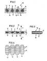
- Fig. 1 eine Platte nach der Erfindung vor dem Walzen des Gewebes in einem Teil-Längsschnitt durch die Schußdrähte,
- Fig. 2 die Platte nach der Erfindung nach dem Walzvorgang in einer der Fig. 1 entsprechenden Darstellung,
- Fig. 3 den Gegenstand der Fig. 2 in einem Teil-Querschnitt nach Linie III-III
- Fig. 4 die Platte nach Fig. 2 in einer Teil-Draufsicht.
- 1 is a plate according to the invention before rolling the fabric in a partial longitudinal section through the weft wires,
- 2 shows the plate according to the invention after the rolling process in a representation corresponding to FIG. 1,
- Fig. 3 shows the subject of Fig. 2 in a partial cross section along line III-III
- Fig. 4 shows the plate of FIG. 2 in a partial plan view.
In den Zeichnungen ist mit 10 eine Drahtgewebeplatte mit Köperbindung bezeichnet, deren außenliegende Drähte 11 monofile Metalldrähte sind, welche die Kette des Gewebes bilden. Die von den außenliegenden Drähten 11 eingebundenen, innenliegenden Schußdrähte 12, die im Gewebe geradlinig, d.h. ungekröpft, durchlaufen, bestehen aus Drahtbündeln, deren dünne Einzeldrähte 13 bei dem hier dargestellten Ausführungsbeispiel drilliert oder miteinander verseilt sind.In the drawings, 10 denotes a woven wire plate with a twill weave, the
Während die außenliegenden Drähte 11 monofile Stahldrähte sind, bestehen die Drahtbündel oder Litzen 12 aus dünnen Nickeldrähten.While the
Nach dem Weben hat das Drahtgewebe 10 die in Fig. 1 dargestellte Form. Danach wird das Gewebe in Längsrichtung 14 seiner außenliegenden, monofilen Drähte 11 in einem oder mehreren Durchgängen zwischen Walzenpaaren gewalzt und hierdurch auf weniger als die Hälfte seiner ursprünglichen Dicke d gebracht, so daß es den in Fig. 2 dargestellten Längsschnitt annimmt. Man erkennt, daß das Gewebe sich durch den Walzvorgang nur unwesentlich längt und daß die im Umriß zunächst runden Drahtbündel eine im Querschnitt spitzovale Form annehmen, wobei sich die Einzeldrähte 13 im Querschnitt verformen und die unmittelbar nach dem Webvorgang im Gewebe noch vorhandenen offenen Zwickel 15 an den Kreuzungsstellen zwischen den außenliegenden Drähten ausfüllen. Da sich diese außenliegenden Drähte nicht nur im Längsschnitt kreuzen (Fig. 2), sondern auch im Grundriß übereinanderlaufen (Fig. 4), hat die fertiggewalzte Gewebeplatte keine von oben nach unten durchgehende Öffnung, durch welche feinkörnige Feststoffe hindurchfallen könnten. Außerdem werden die Oberflächen 16 der dicht nebeneinanderliegenden Außendrähte 11 durch den Walzvorgang abgeflacht und bilden eine praktisch geschlossene Oberfläche, die nur sehr feine Spalten und Löcher hat, durch die zwar Luft oder andere Gase hindurchtreten können, die aber keinerlei Feststoffe oberhalb der geforderten Korngröße durchfallen läßt. Die Größe der Öffnungen kann durch die Walzung beeinflußt werden.After weaving, the
Die so gewalzte Drahtgewebeplatte kann anschließend noch einer Wärmebehandlung unterworfen werden, um innere Spannungen zu beseitigen, die durch den Web- und Walzvorgang hervorgerufen wurden.The wire mesh plate rolled in this way can then be subjected to a heat treatment in order to remove internal stresses which were caused by the weaving and rolling process.
Durch die erfindungsgemäße Konstruktion erlangt die Drahtgewebeplatte nach dem Walzvorgang eine hohe Festigkeit und annähernd die Steifigkeit und Eigenschaften einer Blechplatte, so daß sie mit besonderem Vorteil für die Herstellung von Rinnen, Rohren und Behältern zum Fluidisieren von pulverförmigen Feststoffen verwendet werden kann. Obgleich die innen- und außenliegenden Drähte bzw. Drahtbündel nicht miteinander verschweißt oder versintert sind, ist es möglich, das Gewebe wie eine Blechplatte zu bearbeiten und untereinander oder mit anderen Blechen zu verschweißen.The construction according to the invention gives the wire mesh plate a high strength after the rolling process and approximately the rigidity and properties of a sheet metal plate, so that it can be used with particular advantage for the production of channels, pipes and containers for fluidizing powdery solids. Although the internal and external wires or wire bundles are not welded or sintered to one another, it is possible to process the fabric like a sheet metal plate and to weld it to one another or to other sheets.
Die Erfindung ist nicht auf das dargestellte und beschriebene Ausführungsbeispiel beschränkt, sondern es sind mehrere Änderungen und Ergänzungen möglich, ohne den Rahmen der Erfindung zu verlassen. Beispielsweise ist es möglich, die Kettdrähte als geradlinig durchlaufende Drahtbündel auszubilden oder andere Gewebebindungen wie eine Fünfschaftbindung vorzusehen. Für spezielle Anwendungszwecke können die Drähte, insbesondere die Einzeldrähte der Drahtbündel auch Kunststoffdrähte sein. Die Verwendung von Kunststoffdrähten empfiehlt sich insbesondere dann, wenn das Drahtgewebe nach der Erfindung mit Säuren in Verbindung kommt, welche Metalle stark angreifen.The invention is not limited to the exemplary embodiment shown and described, but several changes and additions are possible without leaving the scope of the invention. For example, it is possible to form the warp wires as a straight wire bundle or to provide other weaves such as a five-shaft weave. For special applications, the wires, in particular the individual wires of the wire bundles, can also be plastic wires. The use of plastic wires is particularly recommended when the wire mesh according to the invention comes into contact with acids which strongly attack metals.
Claims (11)
Applications Claiming Priority (2)
| Application Number | Priority Date | Filing Date | Title |
|---|---|---|---|
| DE3614680 | 1986-04-30 | ||
| DE19863614680 DE3614680A1 (en) | 1986-04-30 | 1986-04-30 | PLATE, IN PARTICULAR FOR THE PRODUCTION OF FLUIDIZING DEVICES AND METHOD FOR THEIR PRODUCTION |
Publications (2)
| Publication Number | Publication Date |
|---|---|
| EP0243594A2 true EP0243594A2 (en) | 1987-11-04 |
| EP0243594A3 EP0243594A3 (en) | 1988-08-03 |
Family
ID=6299892
Family Applications (1)
| Application Number | Title | Priority Date | Filing Date |
|---|---|---|---|
| EP87102278A Withdrawn EP0243594A3 (en) | 1986-04-30 | 1987-02-18 | Plate, especially for the construction of a fluidizing device, and method of manufacturing it |
Country Status (3)
| Country | Link |
|---|---|
| EP (1) | EP0243594A3 (en) |
| DE (1) | DE3614680A1 (en) |
| NO (1) | NO871815L (en) |
Cited By (1)
| Publication number | Priority date | Publication date | Assignee | Title |
|---|---|---|---|---|
| EP1816095A1 (en) * | 2006-02-07 | 2007-08-08 | IBAU Hamburg Ingenieurgesellschaft | Device for pneumatically conveying pulverulent material |
Family Cites Families (3)
| Publication number | Priority date | Publication date | Assignee | Title |
|---|---|---|---|---|
| DE934696C (en) * | 1952-11-25 | 1955-11-03 | Carl Haver & Ed Boecker | Porous pad for pneumatic conveyors |
| DE1236182B (en) * | 1965-07-30 | 1967-03-09 | Becker & Van Huellen | Mesh for pressed material to be formed into plate-like structures in presses, preferably chipboard |
| DE1961050B2 (en) * | 1969-12-05 | 1979-09-20 | Duerener Metalltuch Schoeller, Hoesch & Co, 5160 Dueren | Metal wire mesh |
-
1986
- 1986-04-30 DE DE19863614680 patent/DE3614680A1/en not_active Withdrawn
-
1987
- 1987-02-18 EP EP87102278A patent/EP0243594A3/en not_active Withdrawn
- 1987-04-30 NO NO871815A patent/NO871815L/en unknown
Cited By (2)
| Publication number | Priority date | Publication date | Assignee | Title |
|---|---|---|---|---|
| EP1816095A1 (en) * | 2006-02-07 | 2007-08-08 | IBAU Hamburg Ingenieurgesellschaft | Device for pneumatically conveying pulverulent material |
| US7329071B2 (en) | 2006-02-07 | 2008-02-12 | Ibau Hamburg Ingenieurgesellschaft Industriebau Mbh | Device for the pneumatic conveying of particulate and powdery bulk material |
Also Published As
| Publication number | Publication date |
|---|---|
| EP0243594A3 (en) | 1988-08-03 |
| NO871815L (en) | 1987-11-02 |
| DE3614680A1 (en) | 1987-11-05 |
| NO871815D0 (en) | 1987-04-30 |
Similar Documents
| Publication | Publication Date | Title |
|---|---|---|
| DE1924449C3 (en) | Gas- and liquid-permeable knitted wire composite body of multilayer structure and process for the production of the same | |
| DE3686638T2 (en) | METHOD FOR PRODUCING TITANIUM-NICKEL ALLOYS. | |
| DE2942815C2 (en) | Sheet metal composite | |
| DE4201791A1 (en) | FLAT TUBES FOR INSTALLATION IN A FLAT TUBE HEAT EXCHANGER AND METHOD FOR SEPARATING THE FLAT TUBES | |
| EP0505832A1 (en) | Filter or catalyst body | |
| DE3249345T1 (en) | Safety bar | |
| DE4424936A1 (en) | Pulp mould and production method for this, and formed pulp article and production method for this | |
| EP1421230A2 (en) | Method for manufacturing airbag fabrics | |
| DE2517857C2 (en) | Device for separating magnetizable particles from a suspension | |
| EP1397191B1 (en) | Exhaust gas particulate filter made of sintered metal | |
| EP0243594A2 (en) | Plate, especially for the construction of a fluidizing device, and method of manufacturing it | |
| DE3013560A1 (en) | HIGH OVEN CORSET COOLING DEVICE | |
| DE102017213515B4 (en) | Honeycomb structure forming tool | |
| DE4101919A1 (en) | Ductile metal plate mfr. | |
| DE1115699B (en) | Process for the production of fine-pored perforated sheets from fine metallic wire mesh | |
| DE2933263A1 (en) | Double weave fabric mfg. - uses additional warps which give layer bonding and float between layers | |
| DE10257962C5 (en) | Lightweight component made of hollow spheres | |
| EP1418261A1 (en) | Woven wire fabric | |
| DE2114852B2 (en) | Method for manufacturing a metal body | |
| DE10301037A1 (en) | Exhaust gas particle filter used for removing particles from exhaust gas stream of diesel engine comprises metal support with openings and on which porous sintered metal powder is bound by sintering process | |
| DE3132998C2 (en) | Filter element for bag filters | |
| DE3445496C2 (en) | Conveyor belt | |
| DE2057855A1 (en) | Process for the production of lengths of a multilayer composite from transition feedstock | |
| DE1753524C (en) | Weaving wire made of plastic for endless paper machine screens and continuous extrusion process for producing the weaving wire | |
| DE102008029083A1 (en) | Filter device for filtration of gas, has filter body with open wire mesh, where wire mesh consists of chained wires and weft wires resulting in mesh openings in between |
Legal Events
| Date | Code | Title | Description |
|---|---|---|---|
| PUAI | Public reference made under article 153(3) epc to a published international application that has entered the european phase |
Free format text: ORIGINAL CODE: 0009012 |
|
| AK | Designated contracting states |
Kind code of ref document: A2 Designated state(s): CH DE ES FR GB IT LI NL |
|
| 17P | Request for examination filed |
Effective date: 19880122 |
|
| PUAL | Search report despatched |
Free format text: ORIGINAL CODE: 0009013 |
|
| AK | Designated contracting states |
Kind code of ref document: A3 Designated state(s): CH DE ES FR GB IT LI NL |
|
| 17Q | First examination report despatched |
Effective date: 19881104 |
|
| STAA | Information on the status of an ep patent application or granted ep patent |
Free format text: STATUS: THE APPLICATION HAS BEEN WITHDRAWN |
|
| 18W | Application withdrawn |
Withdrawal date: 19900912 |
|
| RIN1 | Information on inventor provided before grant (corrected) |
Inventor name: SCHOELLER, JOCHEN, DIPL.-ING. |