EP0243586A2 - Système de serrure électromécanique avec clé individuelle - Google Patents
Système de serrure électromécanique avec clé individuelle Download PDFInfo
- Publication number
- EP0243586A2 EP0243586A2 EP87101313A EP87101313A EP0243586A2 EP 0243586 A2 EP0243586 A2 EP 0243586A2 EP 87101313 A EP87101313 A EP 87101313A EP 87101313 A EP87101313 A EP 87101313A EP 0243586 A2 EP0243586 A2 EP 0243586A2
- Authority
- EP
- European Patent Office
- Prior art keywords
- key
- lock
- memory
- code
- locking
- Prior art date
- Legal status (The legal status is an assumption and is not a legal conclusion. Google has not performed a legal analysis and makes no representation as to the accuracy of the status listed.)
- Withdrawn
Links
- 230000015654 memory Effects 0.000 claims abstract description 37
- 230000005662 electromechanics Effects 0.000 claims abstract description 6
- 230000005540 biological transmission Effects 0.000 claims description 17
- 238000013475 authorization Methods 0.000 claims description 16
- 238000009434 installation Methods 0.000 claims description 3
- 238000004519 manufacturing process Methods 0.000 claims description 2
- 230000000712 assembly Effects 0.000 abstract 1
- 238000000429 assembly Methods 0.000 abstract 1
- 230000004048 modification Effects 0.000 abstract 1
- 238000012986 modification Methods 0.000 abstract 1
- 230000008878 coupling Effects 0.000 description 9
- 238000010168 coupling process Methods 0.000 description 9
- 238000005859 coupling reaction Methods 0.000 description 9
- 238000011156 evaluation Methods 0.000 description 7
- 230000004913 activation Effects 0.000 description 4
- 238000003780 insertion Methods 0.000 description 4
- 230000037431 insertion Effects 0.000 description 4
- 238000005452 bending Methods 0.000 description 3
- 238000000034 method Methods 0.000 description 3
- 238000012544 monitoring process Methods 0.000 description 3
- 230000008569 process Effects 0.000 description 3
- 230000006854 communication Effects 0.000 description 2
- 238000010586 diagram Methods 0.000 description 2
- 238000005265 energy consumption Methods 0.000 description 2
- 238000005259 measurement Methods 0.000 description 2
- 230000000903 blocking effect Effects 0.000 description 1
- 230000008859 change Effects 0.000 description 1
- 238000004891 communication Methods 0.000 description 1
- 238000010276 construction Methods 0.000 description 1
- 238000013461 design Methods 0.000 description 1
- 230000008030 elimination Effects 0.000 description 1
- 238000003379 elimination reaction Methods 0.000 description 1
- 230000006870 function Effects 0.000 description 1
- 230000007246 mechanism Effects 0.000 description 1
- 239000002184 metal Substances 0.000 description 1
- 230000007935 neutral effect Effects 0.000 description 1
- 230000003287 optical effect Effects 0.000 description 1
- 238000012545 processing Methods 0.000 description 1
- 230000009467 reduction Effects 0.000 description 1
- 230000004044 response Effects 0.000 description 1
- 230000001360 synchronised effect Effects 0.000 description 1
Images

Classifications
-
- E—FIXED CONSTRUCTIONS
- E05—LOCKS; KEYS; WINDOW OR DOOR FITTINGS; SAFES
- E05B—LOCKS; ACCESSORIES THEREFOR; HANDCUFFS
- E05B47/00—Operating or controlling locks or other fastening devices by electric or magnetic means
- E05B47/06—Controlling mechanically-operated bolts by electro-magnetically-operated detents
- E05B47/0611—Cylinder locks with electromagnetic control
- E05B47/0638—Cylinder locks with electromagnetic control by disconnecting the rotor
- E05B47/0642—Cylinder locks with electromagnetic control by disconnecting the rotor axially, i.e. with an axially disengaging coupling element
-
- G—PHYSICS
- G07—CHECKING-DEVICES
- G07C—TIME OR ATTENDANCE REGISTERS; REGISTERING OR INDICATING THE WORKING OF MACHINES; GENERATING RANDOM NUMBERS; VOTING OR LOTTERY APPARATUS; ARRANGEMENTS, SYSTEMS OR APPARATUS FOR CHECKING NOT PROVIDED FOR ELSEWHERE
- G07C9/00—Individual registration on entry or exit
- G07C9/00174—Electronically operated locks; Circuits therefor; Nonmechanical keys therefor, e.g. passive or active electrical keys or other data carriers without mechanical keys
- G07C9/00182—Electronically operated locks; Circuits therefor; Nonmechanical keys therefor, e.g. passive or active electrical keys or other data carriers without mechanical keys operated with unidirectional data transmission between data carrier and locks
-
- E—FIXED CONSTRUCTIONS
- E05—LOCKS; KEYS; WINDOW OR DOOR FITTINGS; SAFES
- E05B—LOCKS; ACCESSORIES THEREFOR; HANDCUFFS
- E05B47/00—Operating or controlling locks or other fastening devices by electric or magnetic means
- E05B2047/0092—Operating or controlling locks or other fastening devices by electric or magnetic means including means for preventing manipulation by an external magnetic field, e.g. preventing opening by using a strong magnet
-
- G—PHYSICS
- G07—CHECKING-DEVICES
- G07C—TIME OR ATTENDANCE REGISTERS; REGISTERING OR INDICATING THE WORKING OF MACHINES; GENERATING RANDOM NUMBERS; VOTING OR LOTTERY APPARATUS; ARRANGEMENTS, SYSTEMS OR APPARATUS FOR CHECKING NOT PROVIDED FOR ELSEWHERE
- G07C9/00—Individual registration on entry or exit
- G07C9/00174—Electronically operated locks; Circuits therefor; Nonmechanical keys therefor, e.g. passive or active electrical keys or other data carriers without mechanical keys
- G07C2009/00753—Electronically operated locks; Circuits therefor; Nonmechanical keys therefor, e.g. passive or active electrical keys or other data carriers without mechanical keys operated by active electrical keys
- G07C2009/00761—Electronically operated locks; Circuits therefor; Nonmechanical keys therefor, e.g. passive or active electrical keys or other data carriers without mechanical keys operated by active electrical keys with data transmission performed by connected means, e.g. mechanical contacts, plugs, connectors
Definitions
- the invention relates to a cylinder lock and / or locking system with at least one lock containing a changeable coding and decoding device and at least one key which can be made suitable or unsuitable as a master or secondary key.
- a locking system in which programmable locks connected to a central unit and programmable keys are available, in which a master key can make secondary keys suitable or not suitable.
- This system requires external electronics and the connection of locks by means of a central unit, as well as an external power supply and an additional magnetic field to carry out the actual locking process.
- a key-specific code stored in the lock, but also a code relating only to this lock is stored in the key, so that for each lock for which the key receives a locking authorization , memory locations are occupied in the key.
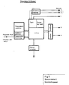
- All previously known locks consist of 3 components and an external energy supply. These 3 components are the electronic control and monitoring unit, the electromechanical unit and the locking unit.
- the electronic control and monitoring unit is used for storing, coding and decoding Key codes, as well as the recognition of locking authorization.
- the electromechanical unit either actuates a lock or a bolt, that is to say the locking unit, or clears the way for actuating the locking unit.
- the previously known constructive solutions of electronic locks are so space and energy consuming that, for example, in addition to the lock and lock cylinder, an electronic component, an electromechanical component and an external power supply have to be accommodated. Such a construction takes up a lot of space and is costly
- These solutions have the traditional relationship between a key and a lock, so it is not possible to lock a large number of locks with as few keys as possible without losing security.
- the invention seeks to remedy this.
- the invention as characterized in the claims, solves the task of a space-saving electronic lock to replace conventional lock cylinders without structural changes and elimination of the relationship between key and lock required by mechanical coding without security loss in that an initially neutral lock the codes receives all those keys that are authorized to lock and, because it is a mechanical unit key, can also lock.
- the essence of the solution is that the electronic control and monitoring unit can be completely housed in the lock cylinder, for example a standard lock according to DIN 18 252.
- a part of the electronics that is not required for the pure locking authorization check, such as memory programming, querying the entire memory allocation, checking whether a key is authorized to give further keys locking authorization len, outsourced to a separate mobile service device.
- the lock part contains a memory in the lock cylinder, in which key codes can be saved and deleted using looo.
- Each key receives an individual code, a processor and a power supply, with each key mechanically fitting into each lock.
- Each lock can now be entered by means of a service device, which key is to be given a locking authorization and, if necessary, which key is to be withdrawn from a locking authorization once it has been stored.
- each key has an individual code and duplicates, as were previously the case with locks that should be locked by different people, would endanger security. Instead of issuing duplicates for a lock that should be able to be locked by different people, all codes of the keys with locking authorization are stored in the lock. Then different people who only have one key can do so close identical (identical) locks as well as locks that others cannot close.
- the simple design enables manufacturing costs that do not exceed those of conventional locking cylinders, so that use is not limited to areas with increased security requirements.
- the key Fig. 1.2 consists of a standardized shaft part and a freely and individually designable handle part.
- the shaft part is designed in such a way that each key mechanically fits into each key channel of each cylinder core.
- the key shaft transmits energy and data in the cylinder core at defined points and, due to its nature, is able to transmit the required mechanical locking forces to the lock bit.
- Energy is preferably transmitted via galvanic connections (contacts).
- the data can either be transmitted via galvanic connections (contacts) or contactlessly via optical elements (e.g. via LED or LASER diodes).
- the handle part Fig. 1.2 and Fig. 5 contains the primary and secondary power supply (eg active and replacement battery terie), the clock generator, the processor, the program memory, the number memory, the programming control, the transmitter and receiver, and the error display.
- the primary and secondary power supply eg active and replacement battery terie
- the number memory contains a single, unique code once assigned.
- the cylinder core is preferably freely rotatable in the cylinder housing. In this case, it contains a standard opening on one side, into which the shaft of the key fits. This side is protected by a hard metal disc Fig. 1.5. Behind it is an electrically insulating part Fig. 1.6, which contains the necessary contacts and decoding and activation unit. This part is secured by the guide Fig. 2 against rotation to the cylinder core.
- FIG. 1 Behind part 6 of Fig. 1 is the freely movable coupling part Fig. 1.4, which is also secured by the guide Fig. 2 against rotation to the cylinder core, but can be moved axially.
- This coupling part is provided with a groove on which the coil Fig. 1.7 is applied.
- the coupling part can snap into the grooves Fig. 1.9 (on part 3) of the lock bit Fig. 1.3 and thus enable the power transmission of the key Fig. 1.2 to the lock bit Fig. 1.3.
- This arrangement prevents an unauthorized coupling of the lock cylinder to the lock bit being made possible by applying an external strong magnetic field.
- the spring Fig. 1.1o ensures safe decoupling of the clasp from the lock bit when the coil is not activated. Due to the symmetrical structure of the locking system, use from opposite sides is possible.
- the dimensions selected in the description above are based on the standards of the most frequently used locking cylinder according to DIN 18 252.
- the explained mechanics, electronics and electromechanics can also be accommodated in smaller and larger cylinder cores.
- the reduction in the external dimensions of the locking cylinder is only limited by the dimension of the key shaft.
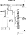
- the control unit itself consists of a central processor unit (CPU), a clock generator, a power-up reset and the data transmission and reception unit.
- the power-up reset ensures a defined initial state of the complete unit after the energy has been switched on.
- the clock generator generates the clocks required for the CPU and the transmitting and receiving unit. Furthermore, a synchronization clock is generated for the evaluation unit in the cylinder core and transferred via the transmission element Fig. 5.4.
- the program in the CPU contains all communication processes to the control and evaluation unit in the cylinder core, the variable coding algorithm, the individual code number and a special programming process.
- the CPU manages all program parts and evaluates the responses coming from the control and evaluation unit of the cylinder core.
- the transmitter and receiver unit converts the computer signals accordingly to the transmission parameters in send signals, or receive signals in computer signals.
- a special feature is the internal programming control for the subsequent programming of the key number. External access to address and data lines is not necessary, as is the case with conventional programming of this memory, but is made possible internally by special programming hardware and the associated programming sequence.
- a protocol is sent to the CPU via the transmission element 5 and the associated receiver, on the basis of which the programming sequence is called and which in turn puts the programming hardware into operation.
- the key code is transferred to the CPU by a handshake process, which then requests the external programming pulse on transmission element 7, as a result of which the key code is permanently programmed into the memory.
- the transmission element Fig. 5.7 is part of the control unit and can only be accessed by the authorized programming unit before installation in the key. After successful and verified programming, the transmission element 7 is electrically disconnected from the control unit and is therefore inoperative forever.
- the electrically insulating part Fig. 1.6 contains all transmission elements, the control and evaluation unit, as well as the bridge of the transmission elements Fig. 1.2 and Fig. 1.3 for energizing the key.
- the control and evaluation unit is normally supplied with energy from the key.
- the control and evaluation unit consists of a central processor unit (CPU), clock synchronization, a power-up reset, the data transmission and reception unit, several memory groups, the memory programming device, a lock activation, a lock coupling measurement system, an alarm unit and the device_an additional energy supply.
- the power-up reset ensures a defined initial state of the complete unit after the energy has been switched on.
- the clock synchronizer receives the synchronization clock from the key via the transmission element Fig. 5.4 and derives therefrom all necessary clock signals for the CPU and the transmitting and receiving unit in a synchronized manner.
- the program in the CPU includes all communication flows to and from the key, the variable coding - algorithm, the particular programming sequence for storing fixed value numbers, the management of the number memory, the measurement and activation of the coupling part, and an alarm evaluation and reporting and a ring memory.
- the transmitting and receiving unit converts the computer signals according to the transmission parameters into transmission signals, or reception signals into computer signals.
- the memory programming device works analogously to that in the key. The only difference is that there is much more memory space for codes and the programming routine manages a correspondingly larger memory.
- the lock activation switches when authorization is recognized the key to the energy on the electromechanical part and thus couples the freely rotatable cylinder core with the lock bit, which enables the power transmission from the key to the lock.
- the energy supply is switched off and the lock can be actuated until the key is removed from the cylinder core by locking by means of the bending spring FIG. 4.
- locking pin Fig. 4.11 blocks the coupling in the second cylinder core.
- the bending spring is thus against a groove in part Fig. 4.4 by the pin Fig. 4.5. pressed that after coupling of part Fig. 4.4 it slides over the edge of the groove and remains on the back of part Fig. 4.4, so that it can no longer move back to its starting position and thus via the locking pin, the coupling of the opposite one Fig. 4.4 is prevented.
- the key is inserted, it cannot be locked from the opposite side.
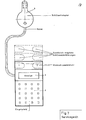
- the service device contains at least 2 sockets Fig. 7.1. and 7.2 for socket wrenches, a socket wrench adapter Fig. 7.3, a display field Fig. 7.4 and an input field Fig. 7.5, as well as the required transmission, reception and processing electronics and their energy supply.
- the service device is used to store key codes in the lock's memory. To do this, the key adapter is pushed into the key channel of the locking cylinder. The device then checks whether any code of a key is already stored in the lock's memory. If no key code has yet been stored, the code of the key which is inserted in the socket wrench insertion 1 is stored. This key (or the keys, if a key is also in socket wrench insertion 2 e) is then authorized in the future to grant or withdraw other keys.
- any further programming of key codes in the lock's memories takes place in such a way that the key, the code of which is to be stored in the lock memory, is inserted into the socket insertion 2 at the service device; the servo device then checks whether the key is inserted in socket wrench insertion 1, the code of which is stored in the lock at the 1st position and, if applicable, the new key code is stored; where a number appears in the display field Fig. 7.4, indicating the number at which the new key is stored.
- To delete a locking authorization of a key it is then sufficient to insert the key with programming authorization for this lock into the socket entry No. 1 and then to type in the location number of the key whose locking authorization is to be deleted. At no point does the code itself come to light.
Landscapes
- Physics & Mathematics (AREA)
- Engineering & Computer Science (AREA)
- Computer Networks & Wireless Communication (AREA)
- General Physics & Mathematics (AREA)
- Electromagnetism (AREA)
- Lock And Its Accessories (AREA)
Applications Claiming Priority (2)
| Application Number | Priority Date | Filing Date | Title |
|---|---|---|---|
| DE3602989 | 1986-01-31 | ||
| DE19863602989 DE3602989A1 (de) | 1986-01-31 | 1986-01-31 | Elektromechanisches schlosssystem |
Publications (2)
| Publication Number | Publication Date |
|---|---|
| EP0243586A2 true EP0243586A2 (fr) | 1987-11-04 |
| EP0243586A3 EP0243586A3 (fr) | 1989-03-01 |
Family
ID=6293093
Family Applications (1)
| Application Number | Title | Priority Date | Filing Date |
|---|---|---|---|
| EP87101313A Withdrawn EP0243586A3 (fr) | 1986-01-31 | 1987-01-30 | Système de serrure électromécanique avec clé individuelle |
Country Status (2)
| Country | Link |
|---|---|
| EP (1) | EP0243586A3 (fr) |
| DE (1) | DE3602989A1 (fr) |
Cited By (18)
| Publication number | Priority date | Publication date | Assignee | Title |
|---|---|---|---|---|
| EP0497040A1 (fr) * | 1991-01-31 | 1992-08-05 | Meridian, Inc. | Unité amovible de programmation pour classeur |
| DE4201568A1 (de) * | 1992-01-22 | 1993-07-29 | Vdo Schindling | Verfahren zur synchronisation von sender und empfaenger |
| EP0597373A1 (fr) * | 1992-11-10 | 1994-05-18 | Zexel Corporation | Dispositif d'entrée de données pour un système de serrure comportant une clé active |
| DE19507043A1 (de) * | 1995-03-01 | 1996-09-05 | Deutsche Telekom Ag | Verfahren zur Erzeugung und Verteilung unpersonalisierter vertraulicher elektronischer Schlüssel |
| US5605066A (en) * | 1992-04-16 | 1997-02-25 | Abloy Security Ltd Oy | Electromechanical lock arrangement |
| EP0780531A1 (fr) * | 1995-12-18 | 1997-06-25 | James Salvatore Bianco | Serrure électronique compacte |
| US5745044A (en) * | 1990-05-11 | 1998-04-28 | Medeco Security Locks, Inc. | Electronic security system |
| AU698600B2 (en) * | 1994-12-29 | 1998-11-05 | James Baber Rowe | Prevention of adverse behaviour, diarrhoea, skin disorders and infections of the hindgut associated with acidic conditions in humans and animals |
| US6005487A (en) * | 1990-05-11 | 1999-12-21 | Medeco Security Locks, Inc. | Electronic security system with novel electronic T-handle lock |
| WO2005001224A1 (fr) * | 2003-06-23 | 2005-01-06 | Buga Technologies Gmbh | Barillet electromagnetique |
| EP1707712A1 (fr) * | 2005-03-30 | 2006-10-04 | WFE Technology Corp. | Ensemble barillet de serrure avec mécanisme mécanique et électronique |
| EP1619632A3 (fr) * | 1999-12-08 | 2008-03-12 | Winfield Locks, Inc., doing business as Computerized Security Systems | Serrure Electronique |
| EP2110501A2 (fr) | 2008-04-14 | 2009-10-21 | ASTRA Gesellschaft für Asset Management mbH & Co. KG | Agencement de cylindre de fermeture |
| US7845202B2 (en) | 2006-09-22 | 2010-12-07 | Assa Abloy Ab | Interchangeable electromechanical lock core |
| US8028553B2 (en) | 2005-06-24 | 2011-10-04 | Assa Abloy Ab | Modular electromechanical lock cylinder |
| US8122746B2 (en) | 1995-09-29 | 2012-02-28 | Hyatt Jr Richard G | Electromechanical cylinder plug |
| US8528373B2 (en) | 1997-06-06 | 2013-09-10 | Richard G. Hyatt, Jr. | Electronic cam assembly |
| US12037814B2 (en) | 2019-10-03 | 2024-07-16 | Swedlock Ab | Electromechanical lock assembly with annular element, blocking and retaining devices |
Families Citing this family (19)
| Publication number | Priority date | Publication date | Assignee | Title |
|---|---|---|---|---|
| DE3918445C1 (fr) * | 1989-06-06 | 1990-12-20 | Anatoli Dipl.-Ing. 3013 Barsinghausen De Stobbe | |
| DE4117721C1 (en) * | 1991-05-30 | 1992-07-02 | Hans Dr. Dr. 6800 Mannheim De Schreiber | Operating electronically controlled programmable lock - transferring light pulses from key to microprocessor chip via light conductor and photodiode to operate electromagnet(s) via power amplifier(s) |
| DE4314854C2 (de) * | 1993-05-05 | 2003-02-06 | Valeo Deutschland Gmbh & Co | Lenkschloß |
| DE4438832A1 (de) * | 1994-10-31 | 1996-05-02 | Diehl Gmbh & Co | Schloß mit Identträger-Aktivierung |
| DE19509918C2 (de) * | 1995-03-18 | 1997-04-10 | Hajo Weigel | Elektronisches Schloß |
| DE19540990A1 (de) * | 1995-10-28 | 1997-05-22 | Parucha Horst | Fotoschip-Schließ-System |
| DE19603320C2 (de) * | 1996-01-31 | 1999-01-14 | Guenter Uhlmann | Elektronisch programmierbares Schließsystem mit Schloß und Schlüssel |
| DE19613460C2 (de) * | 1996-04-04 | 1998-09-24 | Richard Hoepper | Elektronisches Sicherheitstürschloß für eine Schließanlage |
| DE19618526A1 (de) * | 1996-05-08 | 1997-11-20 | Zangenstein Elektro | Schloßsystem |
| DE19650048A1 (de) * | 1996-12-03 | 1998-06-04 | Bayerische Motoren Werke Ag | Speicher für benutzerindividuelle Einstelldaten von Fahrzeug-Ausrüstungsteilen |
| EP0915220B1 (fr) * | 1997-11-06 | 2008-09-24 | Drumm GmbH | Système de verrouillage mécanique et électronique |
| DE19829958B4 (de) * | 1997-11-06 | 2009-01-15 | Drumm Gmbh | Elektronisch-mechanisches Schließsystem |
| DE19834691A1 (de) | 1998-07-31 | 2000-02-03 | Wilke Heinrich Hewi Gmbh | Schließsystem |
| DE19961160A1 (de) * | 1999-12-17 | 2001-06-21 | Volkswagen Ag | Reisegepäckstück |
| DE102005026910A1 (de) * | 2005-06-10 | 2006-12-14 | Hewi Heinrich Wilke Gmbh | Schließzylinder für ein elektronisches Schließsystem |
| EP1960622B1 (fr) | 2005-12-13 | 2011-11-30 | Yebo Tech (Proprietary) Limited | Système de verrouillage électromécanique |
| EP4314452B1 (fr) * | 2021-04-01 | 2026-03-04 | Swedlock AB | Ensemble serrure électromécanique |
| US20250283353A1 (en) * | 2022-06-30 | 2025-09-11 | Limited Liability Company "Electronic Access" | Electromechanical locking device |
| WO2024177528A1 (fr) * | 2023-02-20 | 2024-08-29 | Общество с ограниченной ответственностью "Электроник Аксес" | Système auto-programmable de contrôle d'accès pour dispositifs électromécaniques de verrouillage |
Family Cites Families (10)
| Publication number | Priority date | Publication date | Assignee | Title |
|---|---|---|---|---|
| DE957726C (de) * | 1957-01-17 | Zeiss Ikon A G Goerzwerk, Berlm-Fnedenau | Doppel zylinderschloß mit einem Kupplungsglied zwischen Schließglied und Schheßzylindern | |
| DE1939858C3 (de) * | 1969-08-05 | 1980-03-13 | Fa. Aug. Winkhaus, 4404 Telgte | Kupplungsvorrichtung für ein Profildoppelzylinderschloß |
| US4073527A (en) * | 1977-01-12 | 1978-02-14 | Schlage Lock Company | Electrically controlled door lock |
| DE3031405C2 (de) * | 1980-08-19 | 1983-01-13 | Leicher GmbH & Co, 8011 Kirchheim | Schließanlage |
| DE3108476A1 (de) * | 1981-03-06 | 1982-10-07 | Egon 5000 Köln Gelhard | Zylinderschloss mit schluessel zur mechanischen und/oder elektromechanischen verriegelung |
| DE3218112C2 (de) * | 1982-05-13 | 1985-04-04 | Klaus Dr. 8022 Grünwald Meister | Verschlußeinrichtung |
| DE3225754A1 (de) * | 1982-07-09 | 1984-01-12 | Hülsbeck & Fürst GmbH & Co KG, 5620 Velbert | Verfahren zur schliesswirksamen wechselwirkung eines schluesselartigen teils mit einem schlossartigen teil |
| GB2124808B (en) * | 1982-07-27 | 1986-06-11 | Nat Res Dev | Security system |
| NO153409C (no) * | 1982-09-02 | 1986-03-12 | Trioving As | Omkodbar elektronisk laas. |
| CH664595A5 (de) * | 1984-03-15 | 1988-03-15 | Bauer Kaba Ag | Elektronisch-mechanischer flachschluessel. |
-
1986
- 1986-01-31 DE DE19863602989 patent/DE3602989A1/de active Granted
-
1987
- 1987-01-30 EP EP87101313A patent/EP0243586A3/fr not_active Withdrawn
Cited By (25)
| Publication number | Priority date | Publication date | Assignee | Title |
|---|---|---|---|---|
| US6005487A (en) * | 1990-05-11 | 1999-12-21 | Medeco Security Locks, Inc. | Electronic security system with novel electronic T-handle lock |
| US5745044A (en) * | 1990-05-11 | 1998-04-28 | Medeco Security Locks, Inc. | Electronic security system |
| EP0497040A1 (fr) * | 1991-01-31 | 1992-08-05 | Meridian, Inc. | Unité amovible de programmation pour classeur |
| US5791177A (en) * | 1991-10-21 | 1998-08-11 | Bianco; James S. | Compact electronic lock |
| DE4201568A1 (de) * | 1992-01-22 | 1993-07-29 | Vdo Schindling | Verfahren zur synchronisation von sender und empfaenger |
| US5605066A (en) * | 1992-04-16 | 1997-02-25 | Abloy Security Ltd Oy | Electromechanical lock arrangement |
| EP0597373A1 (fr) * | 1992-11-10 | 1994-05-18 | Zexel Corporation | Dispositif d'entrée de données pour un système de serrure comportant une clé active |
| US5477213A (en) * | 1992-11-10 | 1995-12-19 | Zexel Corporation | Data input device for IC-key lock system |
| AU698600B2 (en) * | 1994-12-29 | 1998-11-05 | James Baber Rowe | Prevention of adverse behaviour, diarrhoea, skin disorders and infections of the hindgut associated with acidic conditions in humans and animals |
| DE19507043A1 (de) * | 1995-03-01 | 1996-09-05 | Deutsche Telekom Ag | Verfahren zur Erzeugung und Verteilung unpersonalisierter vertraulicher elektronischer Schlüssel |
| DE19507043B4 (de) * | 1995-03-01 | 2006-11-23 | Deutsche Telekom Ag | Verfahren zur Erzeugung und Verteilung unpersonalisierter vertraulicher elektronischer Schlüssel |
| US8141399B2 (en) | 1995-09-29 | 2012-03-27 | Hyatt Jr Richard G | Electromechanical cylinder plug |
| US8122746B2 (en) | 1995-09-29 | 2012-02-28 | Hyatt Jr Richard G | Electromechanical cylinder plug |
| EP0780531A1 (fr) * | 1995-12-18 | 1997-06-25 | James Salvatore Bianco | Serrure électronique compacte |
| US8528373B2 (en) | 1997-06-06 | 2013-09-10 | Richard G. Hyatt, Jr. | Electronic cam assembly |
| EP1619632A3 (fr) * | 1999-12-08 | 2008-03-12 | Winfield Locks, Inc., doing business as Computerized Security Systems | Serrure Electronique |
| US7874190B2 (en) | 2003-06-23 | 2011-01-25 | Assa Abloy Ab | Electromechanical lock cylinder |
| AU2004251188B2 (en) * | 2003-06-23 | 2010-01-21 | Assa Abloy Ab | Electromechanical lock cylinder |
| WO2005001224A1 (fr) * | 2003-06-23 | 2005-01-06 | Buga Technologies Gmbh | Barillet electromagnetique |
| EP1707712A1 (fr) * | 2005-03-30 | 2006-10-04 | WFE Technology Corp. | Ensemble barillet de serrure avec mécanisme mécanique et électronique |
| US8028553B2 (en) | 2005-06-24 | 2011-10-04 | Assa Abloy Ab | Modular electromechanical lock cylinder |
| US7845202B2 (en) | 2006-09-22 | 2010-12-07 | Assa Abloy Ab | Interchangeable electromechanical lock core |
| EP2110501A2 (fr) | 2008-04-14 | 2009-10-21 | ASTRA Gesellschaft für Asset Management mbH & Co. KG | Agencement de cylindre de fermeture |
| EP2110501A3 (fr) * | 2008-04-14 | 2013-04-03 | ASTRA Gesellschaft für Asset Management mbH & Co. KG | Agencement de cylindre de fermeture |
| US12037814B2 (en) | 2019-10-03 | 2024-07-16 | Swedlock Ab | Electromechanical lock assembly with annular element, blocking and retaining devices |
Also Published As
| Publication number | Publication date |
|---|---|
| DE3602989C2 (fr) | 1988-07-28 |
| EP0243586A3 (fr) | 1989-03-01 |
| DE3602989A1 (de) | 1987-11-19 |
Similar Documents
| Publication | Publication Date | Title |
|---|---|---|
| EP0243586A2 (fr) | Système de serrure électromécanique avec clé individuelle | |
| DE2560688C2 (fr) | ||
| DE3905651C2 (fr) | ||
| EP0401647B1 (fr) | Système de verrouillage | |
| DE2928913C2 (de) | Diebstahl-Sicherungsvorrichtung für Kraftfahrzeuge | |
| DE212010000037U1 (de) | Mechatronische schliessvorrichtung | |
| EP0600194B1 (fr) | Système de contrÔle d'accès | |
| EP0811739A2 (fr) | Dispositif et méthode pour vérifier l'autorisation de contrÔle d'accés, en particulier dispositif de fermeture des véhicules | |
| EP0911466B1 (fr) | Dispositif électronique programmable de fermeture sans usure | |
| EP1256671A2 (fr) | Rosette pour serrure cylindrique | |
| DE3031405C2 (de) | Schließanlage | |
| DE19635483A1 (de) | Verfahren und Vorrichtung zur Überwachung von Gegenständen | |
| DE102021114239A1 (de) | Schlüssel mit einer Schlüsselreide und mit einem Schlüsselschaft und einem Generator | |
| DE2635180C3 (de) | Verfahren zur elektronisch gesteuerten Freigabe von Tür-, Safe- und Funktionsschlössern unter Verwendung elektronisch codierter Schlüssel sowie Schaltungsanordnung zur Durchführung des Verfahrens | |
| DE4337262C1 (de) | Telefonkartengesteuertes elektronisches Zugangsberechtigungssystem | |
| DE102011054637A1 (de) | Verfahren zum Konfigurieren eines elektromechanischen Schlosses | |
| EP0132627B1 (fr) | Dispositif de verrouillage actionné électriquement | |
| DE3724407C2 (fr) | ||
| DE10225368C1 (de) | Schließzylinder mit kontaktloser Übertragung eines Signals | |
| DE4341333B4 (de) | Verfahren zum Betreiben einer elektronischen Wegfahrsperre und elektronische Wegfahrsperre für Kraftfahrzeuge | |
| EP4239148A1 (fr) | Dispositif de fermeture | |
| EP1083277B1 (fr) | Système de verrouillage et procéder d'utilisation de celui-ci | |
| EP0915220B1 (fr) | Système de verrouillage mécanique et électronique | |
| DE9419736U1 (de) | Energieautarkes elektronisches Schloß | |
| DE102015109789A1 (de) | Zugangskontrollsystem zur Zugangskontrolle zu einem Bereich und Verfahren zur Inbetriebnahme eines Zugangskontrollsystems zur Zugangskontrolle zu einem Bereich |
Legal Events
| Date | Code | Title | Description |
|---|---|---|---|
| PUAI | Public reference made under article 153(3) epc to a published international application that has entered the european phase |
Free format text: ORIGINAL CODE: 0009012 |
|
| AK | Designated contracting states |
Kind code of ref document: A2 Designated state(s): ES FR GB IT |
|
| XX | Miscellaneous (additional remarks) |
Free format text: EIN ANTRAG GEMAESS REGEL 88 EPUE AUF HINZUFUEGUNG DER FIGUR 4 LIEGT VOR. UEBER DIESEN ANTRAG WIRD IM LAUFE DES VERFAHRENS VON DER PRUEFUNGSABTEILUNG EINE ENTSCHEIDUNG GETROFFEN WERDEN. |
|
| PUAL | Search report despatched |
Free format text: ORIGINAL CODE: 0009013 |
|
| AK | Designated contracting states |
Kind code of ref document: A3 Designated state(s): ES FR GB IT |
|
| 17P | Request for examination filed |
Effective date: 19890315 |
|
| STAA | Information on the status of an ep patent application or granted ep patent |
Free format text: STATUS: THE APPLICATION IS DEEMED TO BE WITHDRAWN |
|
| 18D | Application deemed to be withdrawn |
Effective date: 19910912 |
|
| RIN1 | Information on inventor provided before grant (corrected) |
Inventor name: KORSELT, THOMAS |