EP0243309B1 - Appareil pour surveiller des processus de neutralisation et emploi de l'appareil dans des installations de nettoyage de gaz d'échappement - Google Patents
Appareil pour surveiller des processus de neutralisation et emploi de l'appareil dans des installations de nettoyage de gaz d'échappement Download PDFInfo
- Publication number
- EP0243309B1 EP0243309B1 EP19870810223 EP87810223A EP0243309B1 EP 0243309 B1 EP0243309 B1 EP 0243309B1 EP 19870810223 EP19870810223 EP 19870810223 EP 87810223 A EP87810223 A EP 87810223A EP 0243309 B1 EP0243309 B1 EP 0243309B1
- Authority
- EP
- European Patent Office
- Prior art keywords
- sensor
- cell
- amplifier
- electrode
- circuit
- Prior art date
- Legal status (The legal status is an assumption and is not a legal conclusion. Google has not performed a legal analysis and makes no representation as to the accuracy of the status listed.)
- Expired - Lifetime
Links
Images
Classifications
-
- G—PHYSICS
- G01—MEASURING; TESTING
- G01N—INVESTIGATING OR ANALYSING MATERIALS BY DETERMINING THEIR CHEMICAL OR PHYSICAL PROPERTIES
- G01N27/00—Investigating or analysing materials by the use of electric, electrochemical, or magnetic means
- G01N27/26—Investigating or analysing materials by the use of electric, electrochemical, or magnetic means by investigating electrochemical variables; by using electrolysis or electrophoresis
- G01N27/403—Cells and electrode assemblies
- G01N27/4035—Combination of a single ion-sensing electrode and a single reference electrode
Definitions
- the invention relates to a device for monitoring neutralization processes, with a pH sensor and a circuit connected to it, the pH sensor being an electrochemical cell, an aqueous mass contained in the cell, a diaphragm arranged in the wall of the cell, an in has a reference electrode arranged in the cell and a measuring electrode arranged outside the cell.
- So-called glass electrodes are usually used as sensors or sensors for pH measurement, in which a thin glass membrane which is permeable to hydrogen ions separates a reference electrode arranged in a cell from a measuring electrode located outside this cell.
- aqueous mass of known composition in the cell e.g. Calomel. It has been shown that such pH sensors do not function maintenance-free over a long period of time and that large measurement errors can occur if the medium to be measured contains solid particles. These quickly clog or destroy the sensor membranes. In systems for wet cleaning of exhaust gases in combustion systems, solid parts in the washing liquid are to be expected, and maintenance-free operation over a longer period is also required.
- Prior art FR-A-2 354 558 describes an apparatus for the detection of ions in liquids.
- Glass electrodes serve as measuring and reference electrodes.
- the reference electrode is located in a space between two concentric, electrically insulating shells, between which there is a gelled reference liquid.
- the space containing the reference liquid is closed off by a seal which forms an ion-permeable connection between the reference liquid and the liquid to be tested.
- An electrical circuit for amplifying the weak output signals of the high-volume glass electrodes is cast in the innermost envelope of the device. This device also has the disadvantages of glass electrodes mentioned above.
- FR-A-2 354 558 further proposes to provide three or more glass electrodes as measuring electrodes and to monitor them by means of a comparison circuit. When a difference is found, the comparison circuit triggers an alarm. The measurement is then continued until the device is replaced by the remaining intact glass electrodes. It is obvious that such a device is not suitable for monitoring a system that has to work maintenance-free over a long period of time, as is the case, for example, with a flue gas scrubbing system designed for the heating system of a residential building.
- DE-OS 31 12 997 provides a flue gas scrubber with which the carbon dioxide and sulfur dioxide of the flue gas are washed out by water.
- the wash water is chemically neutralized and then used again for flue gas washing.
- a neutralization container is provided, which has a pH value regulator, which is connected to a metering valve, which is arranged between the tub and the neutralization container.
- European patent application 0 152 742 starts from the fact that burning one kilogram of heating oil produces 0.8 liters of water, which can be condensed and collected in a container.
- the cited application provides a control device for controlling the discharge of a predetermined amount of water when a predetermined water level is reached and for additionally actuating a metering system which dispenses a predetermined amount of a neutralizing agent into the liquid used for washing.
- precise control of the pH cannot be achieved in this way.
- the cleaning effect of the system suffers.
- the device is intended in particular to work for a long time without maintenance not be affected, for example, by solids contained in the liquid, such as calcium carbonate or calcium sulfate.
- the circuit contains an amplifier which applies a feedback voltage to the measuring electrode which corresponds to the voltage which the pH sensor has at the desired working pH. Since the aqueous mass contained in the cell contains the same substances that are also contained in the liquid, the pH value of which is to be checked, the aging of both electrodes is the same during operation, so that the pH sensor has a relatively long life Service life remains largely stable.
- the circuit prevents the pH sensor ⁇ e.g.
- the buffer system described below. It has been shown that the substances contained in the cell act on the metal of the reference electrode. It is assumed that the calcium carbonate forms a metal carbonate on the surface of the reference electrode, which contributes to the formation of a buffer system (pH 9.5) in the cell. On the other hand, the hydrogen ion concentration to be measured comes into effect at the measuring electrode, so that a pH-dependent electrical voltage is generated across both electrodes.
- the electrodes are made of stainless steel, and iron carbonate should form on the reference electrode.
- the diaphragm is advantageously made of ceramic, e.g. porous porcelain. Porcelain has very fine pores through which the electrolyte in the cell comes into contact with the liquid outside the cell. However, there is no risk of the electrolyte being washed out of the cell.
- the feedback voltage has an influence on the electrochemical processes taking place in the sensor by preventing the formation or regeneration of the buffer system after a massive fault, e.g. Dehydration, incorrect use, electrical recharging etc. are supported and thereby make an important contribution to the long-term stability of the sensor.
- the configuration of the circuit described thus creates an extremely stable device for determining the pH.
- the circuit is advantageously designed such that the output of the amplifier is connected via a potentiometer to the non-inverting input of the amplifier, that one electrode of the pH sensor is connected to a current source and the other electrode is connected to the non-inverting input of the Amplifier are connected, and that a resistor is connected in parallel to the pH sensor, which is of the order of magnitude of the internal resistance of the sensor.
- the circuit generates a voltage against the current source via the resistor connected in parallel to the sensor. This is called the feedback voltage and corresponds to the voltage of the sensor at the desired working pH.
- the required feedback voltage can be set with the potentiometer.
- the output of the amplifier is connected to the inverting input of the amplifier via an RC element. This causes the output voltage of the amplifier to follow the sensor voltage while suppressing high-frequency interference signals.
- a voltage divider is expediently provided, the center tap of which is connected to the electrode of the pH sensor. This results in a simple and convenient power supply for the amplifier.
- a load resistor is expediently connected to the output of a suitable operational amplifier. This enables the impedance of the amplifier output to be adjusted.
- a capacitor is advantageously connected between the measuring electrode of the sensor and the ground of the circuit. This derives high-frequency signals and thus helps to stabilize the device.
- the invention also relates to the use of the device for checking the pH of the washing liquid of an exhaust gas cleaning system, in particular one in a combustion system.
- Calcium oxide or calcium hydroxide is advantageously added to the scrubbing liquid of such an exhaust gas cleaning system as a neutralizing agent.
- the pH of the washing liquid is expediently kept in the range from 6 to 6.8. This ensures that practically only calcium sulfate is excreted from the washing liquid. Calcium carbonate is therefore practically not formed. In other words, this means that primarily the sulfur content is separated from the exhaust gas, but not the CO 2 content. In this way, a considerable saving in neutralizing agent is achieved.
- limescale deposits are practically prevented in the car wash, and there is only a relatively small amount of calcium sulfate as a neutralization product, i.e. a harmless substance better known as gypsum.
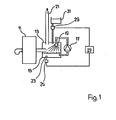
- reference number 11 denotes a boiler and reference number 13 an exhaust gas cleaning system.
- This consists essentially of a container 15, a circulating pump 17 and a spray device 19.
- the exhaust gases from the boiler 11 are therefore guided by a spray rain before they escape from the exhaust gas purification system 13 through the chimney 21.
- a pH sensor 23 is connected to a circuit 25 which supplies a signal corresponding to the measured pH to a control circuit 27. At a predetermined pH value, this delivers a signal for actuating the metering device 29 in order to conduct neutralizing agent from a container 31 into the washing container 15.
- a pH sensor 23 such as may be an exhaust gas washing device, such as is for example shown in Figure 1 used in '.
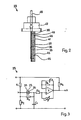
- two electrodes 35, 37 are attached to a central plate 33 made of insulating material, for example made of glass fiber reinforced plastic. These electrodes 35, 37 consist of a metal, for example stainless steel.
- the electrode 37 serves as a reference electrode and is located inside a cell 39.
- the electrode 35 serves as a measuring electrode and is arranged outside the cell 39, where it can be brought into contact with the liquid to be tested.
- the cell 39 contains an aqueous mass containing calcium carbonate and calcium sulfate.
- the cell 39 is formed by the middle plate 33 and a wall 41 made of plastic.
- the wall 41 consists, for example, of polyurethane and is firmly connected to the central plate 33.
- openings 43 in which diaphragms 45, for example made of ceramic material, preferably made of porcelain, are inserted.
- the electrodes 35, 37 are connected in the base 47 to the connecting cable 49, which leads to a circuit 25.
- E o has values from -20 to +20 mV for various sensors.
- the load capacity of the described pH sensor 23 is small. It is of the order of magnitude of a maximum of 10 nA.
- the circuit 25 must be designed so that it can eliminate disturbances from the environment and the measurement load remains sufficiently small. It should have a stabilizing effect on the pH sensor 23. For this purpose, it applies a feedback voltage to the measuring electrode 35 which corresponds to the voltage of the sensor which it has at the working pH.
- the sensor 23 described has the property that when solid particles of the neutralizing agent, for example Ca (OH) 2 , hit the measuring electrode 35, there is a rapid change in the potential difference. This change is determined by the circuit 25.
- the neutralizing agent for example Ca (OH) 2
- the output signal of the circuit 25 is fed to the control circuit 27, which actuates the dosing device 29 when a predetermined pH value is reached in order to switch on or off the supply of neutralizing agent.
- the control circuit 27 actuates the dosing device 29 when a predetermined pH value is reached in order to switch on or off the supply of neutralizing agent.
- precise control of the supply of neutralizing agent is effected. Overdosing can thus be avoided and optimal utilization of the neutralizing agent can be ensured.
- the circuit 25 shown in FIG. 3 has a voltage divider with the resistors R 1 and R 2 .
- the center tap M of the voltage divider R 1 , R 2 is connected to the reference electrode 37 of the pH sensor 23.
- the measuring electrode 35 of the sensor 23 is connected via the resistor R 4 to the non-inverting input of an amplifier V, for example an operational amplifier.
- Resistor R 3 is connected in parallel with pH sensor 23.
- a capacitor C 1 is connected between the measuring electrode 35 and ground.
- a potentiometer P leads to the non-inverting input of operational amplifier V.
- an RC element consisting of resistor R 5 and capacitor C 2 , which are connected in parallel, leads to the inverting input of Operational amplifier V.
- a load resistor R 6 is connected to the output of the operational amplifier.
- the invention is not restricted to the exemplary embodiments described.
- the one described is also conceivable Circuit for pH sensors of a slightly different design.
Landscapes
- Chemical & Material Sciences (AREA)
- Life Sciences & Earth Sciences (AREA)
- Health & Medical Sciences (AREA)
- Physics & Mathematics (AREA)
- Chemical Kinetics & Catalysis (AREA)
- Electrochemistry (AREA)
- Molecular Biology (AREA)
- Analytical Chemistry (AREA)
- Biochemistry (AREA)
- General Health & Medical Sciences (AREA)
- General Physics & Mathematics (AREA)
- Immunology (AREA)
- Pathology (AREA)
- Treating Waste Gases (AREA)
Claims (13)
Priority Applications (1)
| Application Number | Priority Date | Filing Date | Title |
|---|---|---|---|
| AT87810223T ATE57012T1 (de) | 1986-04-21 | 1987-04-08 | Vorrichtung zur ueberwachung von neutralisationsprozessen und verwendung der vorrichtung bei abgasreinigungsanlagen. |
Applications Claiming Priority (2)
| Application Number | Priority Date | Filing Date | Title |
|---|---|---|---|
| CH1635/86 | 1986-04-21 | ||
| CH163586 | 1986-04-21 |
Publications (2)
| Publication Number | Publication Date |
|---|---|
| EP0243309A1 EP0243309A1 (fr) | 1987-10-28 |
| EP0243309B1 true EP0243309B1 (fr) | 1990-09-26 |
Family
ID=4215063
Family Applications (1)
| Application Number | Title | Priority Date | Filing Date |
|---|---|---|---|
| EP19870810223 Expired - Lifetime EP0243309B1 (fr) | 1986-04-21 | 1987-04-08 | Appareil pour surveiller des processus de neutralisation et emploi de l'appareil dans des installations de nettoyage de gaz d'échappement |
Country Status (3)
| Country | Link |
|---|---|
| EP (1) | EP0243309B1 (fr) |
| AT (1) | ATE57012T1 (fr) |
| DE (1) | DE3765162D1 (fr) |
Families Citing this family (1)
| Publication number | Priority date | Publication date | Assignee | Title |
|---|---|---|---|---|
| EP1491519A1 (fr) | 2003-06-25 | 2004-12-29 | Mettler-Toledo GmbH | Procédé de traitement de céramiques poreuses |
Family Cites Families (3)
| Publication number | Priority date | Publication date | Assignee | Title |
|---|---|---|---|---|
| US3440518A (en) * | 1966-10-24 | 1969-04-22 | Beckman Instruments Inc | Voltage-to-current converter for use with measuring instruments |
| US4133732A (en) * | 1976-06-10 | 1979-01-09 | Jan Boeke | Combination electrode system |
| US4404065A (en) * | 1980-01-14 | 1983-09-13 | Enviromental Sciences Associates, Inc. | Electrochemical detection system and method of analysis |
-
1987
- 1987-04-08 AT AT87810223T patent/ATE57012T1/de not_active IP Right Cessation
- 1987-04-08 EP EP19870810223 patent/EP0243309B1/fr not_active Expired - Lifetime
- 1987-04-08 DE DE8787810223T patent/DE3765162D1/de not_active Expired - Lifetime
Also Published As
| Publication number | Publication date |
|---|---|
| ATE57012T1 (de) | 1990-10-15 |
| EP0243309A1 (fr) | 1987-10-28 |
| DE3765162D1 (de) | 1990-10-31 |
Similar Documents
| Publication | Publication Date | Title |
|---|---|---|
| DE69534714T2 (de) | Verfahren und vorrichtung zum steuern der zufuhr von wasserbehandlungschemikalien unter verwendung eines voltametrischen sensors | |
| DE2431677A1 (de) | Gasanalysegeraet | |
| DE2817363A1 (de) | Verfahren zur konzentrationsbestimmung von zucker und dafuer geeigneter elektrokatalytischer zuckersensor | |
| DE19959005A1 (de) | Verfahren und Vorrichtung zur Öl-in-Wasser Messung | |
| DE3405431A1 (de) | Messsonde zu potentiometrischer messung von ionenkonzentrationen, verfahren zu deren herstellung und ihre verwendung | |
| EP0428514B1 (fr) | Procede et dispositif pour analyser des substances contenues dans l'eau d'un liquide d'echantillonnage aqueux | |
| DE2434318A1 (de) | Verfahren und einrichtung zur messung der ionenkonzentration in fluessigkeiten | |
| EP2169393A1 (fr) | Procédé et dispositif destinés à la mesure de la dureté de l'eau | |
| CH634660A5 (de) | Bezugselektrode fuer elektrochemische messanordnung. | |
| EP0740149A1 (fr) | Capteur électrochimique | |
| DE2147725A1 (de) | Vorrichtung zum Bestimmen des Sauerstoffbedarfs in Flüssigkeitsproben | |
| EP0243309B1 (fr) | Appareil pour surveiller des processus de neutralisation et emploi de l'appareil dans des installations de nettoyage de gaz d'échappement | |
| DE2265200C3 (de) | Strömungszelle für Zwecke der elektrochemischen Analyse | |
| EP0282441A2 (fr) | Procédé de détermination de la demande chimique en oxygène de l'eau | |
| CH659327A5 (en) | Method and apparatus for determining the organic carbon content of water or of an aqueous solution | |
| DE3546409A1 (de) | Verfahren und vorrichtung zur selbsttaetigen kalibrierung von chemischen sensoren | |
| DE1523018A1 (de) | Messvorrichtung zur automatischen Messung des Cyanidgehalts und/oder des pH-Wertes von Industrieabwaessern | |
| DE10042846C2 (de) | Verfahren zur qualitativen und/oder quantitativen Charakterisierung polarer Bestandteile in Flüssigkeiten, Elektrodenanordnung zur Durchführung dieses Verfahrens sowie Anwendung des Verfahrens und der Elektrodenanordnung | |
| DE1598597C3 (de) | Elektrolytische Titrieranlage | |
| DE19547670A1 (de) | Amperometrischer Zweielektrodensensor, insbesondere für Wasserstoffperoxid | |
| EP0729576A1 (fr) | Procede et dispositif permettant de determiner des substances dissoutes | |
| DE2416716A1 (de) | Vorrichtung zur bestimmung von chemikalien im pruefungsstrom | |
| CH671710A5 (en) | Circulated boiler fume wash liq. is kept acidic - by controlling lime addn. to prevent carbonate formation | |
| DE1598597B2 (de) | Elektrolytische Titrieranlage | |
| EP0603751B1 (fr) | Méthode pour la détection de composés présents dans une phase liquide comportant un solide |
Legal Events
| Date | Code | Title | Description |
|---|---|---|---|
| PUAI | Public reference made under article 153(3) epc to a published international application that has entered the european phase |
Free format text: ORIGINAL CODE: 0009012 |
|
| AK | Designated contracting states |
Kind code of ref document: A1 Designated state(s): AT BE CH DE ES FR GB GR IT LI LU NL SE |
|
| 17P | Request for examination filed |
Effective date: 19870930 |
|
| 17Q | First examination report despatched |
Effective date: 19890602 |
|
| GRAA | (expected) grant |
Free format text: ORIGINAL CODE: 0009210 |
|
| AK | Designated contracting states |
Kind code of ref document: B1 Designated state(s): AT BE CH DE ES FR GB GR IT LI LU NL SE |
|
| PG25 | Lapsed in a contracting state [announced via postgrant information from national office to epo] |
Ref country code: SE Effective date: 19900926 Ref country code: NL Effective date: 19900926 Ref country code: GR Free format text: LAPSE BECAUSE OF FAILURE TO SUBMIT A TRANSLATION OF THE DESCRIPTION OR TO PAY THE FEE WITHIN THE PRESCRIBED TIME-LIMIT Effective date: 19900926 |
|
| REF | Corresponds to: |
Ref document number: 57012 Country of ref document: AT Date of ref document: 19901015 Kind code of ref document: T |
|
| REF | Corresponds to: |
Ref document number: 3765162 Country of ref document: DE Date of ref document: 19901031 |
|
| RAP2 | Party data changed (patent owner data changed or rights of a patent transferred) |
Owner name: FUELLEMANN PATENT AG |
|
| RIN2 | Information on inventor provided after grant (corrected) |
Free format text: HEIERLI, WERNER |
|
| REG | Reference to a national code |
Ref country code: CH Ref legal event code: PUE Owner name: FUELLEMANN PATENT AG |
|
| ITF | It: translation for a ep patent filed |
Owner name: ING. C. GREGORJ S.P.A. |
|
| ET | Fr: translation filed | ||
| PG25 | Lapsed in a contracting state [announced via postgrant information from national office to epo] |
Ref country code: ES Free format text: LAPSE BECAUSE OF FAILURE TO SUBMIT A TRANSLATION OF THE DESCRIPTION OR TO PAY THE FEE WITHIN THE PRESCRIBED TIME-LIMIT Effective date: 19910106 |
|
| GBT | Gb: translation of ep patent filed (gb section 77(6)(a)/1977) | ||
| NLV1 | Nl: lapsed or annulled due to failure to fulfill the requirements of art. 29p and 29m of the patents act | ||
| ITTA | It: last paid annual fee | ||
| PLBE | No opposition filed within time limit |
Free format text: ORIGINAL CODE: 0009261 |
|
| STAA | Information on the status of an ep patent application or granted ep patent |
Free format text: STATUS: NO OPPOSITION FILED WITHIN TIME LIMIT |
|
| 26N | No opposition filed | ||
| PGFP | Annual fee paid to national office [announced via postgrant information from national office to epo] |
Ref country code: SE Payment date: 19940426 Year of fee payment: 8 |
|
| EPTA | Lu: last paid annual fee | ||
| PGFP | Annual fee paid to national office [announced via postgrant information from national office to epo] |
Ref country code: GB Payment date: 19960322 Year of fee payment: 10 Ref country code: CH Payment date: 19960322 Year of fee payment: 10 |
|
| PGFP | Annual fee paid to national office [announced via postgrant information from national office to epo] |
Ref country code: LU Payment date: 19960401 Year of fee payment: 10 |
|
| PGFP | Annual fee paid to national office [announced via postgrant information from national office to epo] |
Ref country code: BE Payment date: 19960412 Year of fee payment: 10 |
|
| PGFP | Annual fee paid to national office [announced via postgrant information from national office to epo] |
Ref country code: AT Payment date: 19960426 Year of fee payment: 10 |
|
| PGFP | Annual fee paid to national office [announced via postgrant information from national office to epo] |
Ref country code: FR Payment date: 19960430 Year of fee payment: 10 |
|
| PGFP | Annual fee paid to national office [announced via postgrant information from national office to epo] |
Ref country code: DE Payment date: 19960531 Year of fee payment: 10 |
|
| PG25 | Lapsed in a contracting state [announced via postgrant information from national office to epo] |
Ref country code: LU Free format text: LAPSE BECAUSE OF NON-PAYMENT OF DUE FEES Effective date: 19970408 Ref country code: GB Effective date: 19970408 Ref country code: AT Effective date: 19970408 |
|
| PG25 | Lapsed in a contracting state [announced via postgrant information from national office to epo] |
Ref country code: LI Free format text: LAPSE BECAUSE OF NON-PAYMENT OF DUE FEES Effective date: 19970430 Ref country code: CH Free format text: LAPSE BECAUSE OF NON-PAYMENT OF DUE FEES Effective date: 19970430 Ref country code: BE Effective date: 19970430 |
|
| BERE | Be: lapsed |
Owner name: FULLEMANN PATENT A.G. Effective date: 19970430 |
|
| GBPC | Gb: european patent ceased through non-payment of renewal fee |
Effective date: 19970408 |
|
| REG | Reference to a national code |
Ref country code: CH Ref legal event code: PL |
|
| PG25 | Lapsed in a contracting state [announced via postgrant information from national office to epo] |
Ref country code: FR Free format text: LAPSE BECAUSE OF NON-PAYMENT OF DUE FEES Effective date: 19971231 |
|
| PG25 | Lapsed in a contracting state [announced via postgrant information from national office to epo] |
Ref country code: DE Free format text: LAPSE BECAUSE OF NON-PAYMENT OF DUE FEES Effective date: 19980101 |
|
| REG | Reference to a national code |
Ref country code: FR Ref legal event code: ST |
|
| PG25 | Lapsed in a contracting state [announced via postgrant information from national office to epo] |
Ref country code: IT Free format text: LAPSE BECAUSE OF NON-PAYMENT OF DUE FEES;WARNING: LAPSES OF ITALIAN PATENTS WITH EFFECTIVE DATE BEFORE 2007 MAY HAVE OCCURRED AT ANY TIME BEFORE 2007. THE CORRECT EFFECTIVE DATE MAY BE DIFFERENT FROM THE ONE RECORDED. Effective date: 20050408 |