EP0243309B1 - Vorrichtung zur Ueberwachung von Neutralisationsprozessen und Verwendung der Vorrichtung bei Abgasreinigungsanlagen - Google Patents
Vorrichtung zur Ueberwachung von Neutralisationsprozessen und Verwendung der Vorrichtung bei Abgasreinigungsanlagen Download PDFInfo
- Publication number
- EP0243309B1 EP0243309B1 EP19870810223 EP87810223A EP0243309B1 EP 0243309 B1 EP0243309 B1 EP 0243309B1 EP 19870810223 EP19870810223 EP 19870810223 EP 87810223 A EP87810223 A EP 87810223A EP 0243309 B1 EP0243309 B1 EP 0243309B1
- Authority
- EP
- European Patent Office
- Prior art keywords
- sensor
- cell
- amplifier
- electrode
- circuit
- Prior art date
- Legal status (The legal status is an assumption and is not a legal conclusion. Google has not performed a legal analysis and makes no representation as to the accuracy of the status listed.)
- Expired - Lifetime
Links
- 238000006386 neutralization reaction Methods 0.000 title claims abstract description 8
- 238000000034 method Methods 0.000 title claims abstract description 6
- 238000004140 cleaning Methods 0.000 title claims description 12
- 239000007789 gas Substances 0.000 title description 15
- OSGAYBCDTDRGGQ-UHFFFAOYSA-L calcium sulfate Chemical compound [Ca+2].[O-]S([O-])(=O)=O OSGAYBCDTDRGGQ-UHFFFAOYSA-L 0.000 claims abstract description 16
- VTYYLEPIZMXCLO-UHFFFAOYSA-L Calcium carbonate Chemical compound [Ca+2].[O-]C([O-])=O VTYYLEPIZMXCLO-UHFFFAOYSA-L 0.000 claims abstract description 15
- 229910000019 calcium carbonate Inorganic materials 0.000 claims abstract description 7
- 229910052751 metal Inorganic materials 0.000 claims abstract description 6
- 239000002184 metal Substances 0.000 claims abstract description 6
- 230000003139 buffering effect Effects 0.000 claims abstract 2
- 239000007788 liquid Substances 0.000 claims description 28
- 238000005406 washing Methods 0.000 claims description 19
- 239000007787 solid Substances 0.000 claims description 8
- 239000003990 capacitor Substances 0.000 claims description 4
- 238000010438 heat treatment Methods 0.000 claims description 4
- 229910052573 porcelain Inorganic materials 0.000 claims description 4
- 229910001220 stainless steel Inorganic materials 0.000 claims description 4
- 239000010935 stainless steel Substances 0.000 claims description 4
- 239000000919 ceramic Substances 0.000 claims description 2
- 235000011132 calcium sulphate Nutrition 0.000 claims 2
- 239000000159 acid neutralizing agent Substances 0.000 claims 1
- 239000001175 calcium sulphate Substances 0.000 claims 1
- 239000000843 powder Substances 0.000 claims 1
- 239000002912 waste gas Substances 0.000 claims 1
- 239000003795 chemical substances by application Substances 0.000 description 11
- 230000003472 neutralizing effect Effects 0.000 description 11
- 239000011521 glass Substances 0.000 description 8
- UGFAIRIUMAVXCW-UHFFFAOYSA-N Carbon monoxide Chemical compound [O+]#[C-] UGFAIRIUMAVXCW-UHFFFAOYSA-N 0.000 description 5
- 239000003546 flue gas Substances 0.000 description 5
- 239000002245 particle Substances 0.000 description 5
- XLYOFNOQVPJJNP-UHFFFAOYSA-N water Substances O XLYOFNOQVPJJNP-UHFFFAOYSA-N 0.000 description 5
- 230000002378 acidificating effect Effects 0.000 description 4
- 230000015572 biosynthetic process Effects 0.000 description 4
- 239000007853 buffer solution Substances 0.000 description 4
- 238000012544 monitoring process Methods 0.000 description 4
- 230000000694 effects Effects 0.000 description 3
- 238000005259 measurement Methods 0.000 description 3
- 239000000126 substance Substances 0.000 description 3
- CURLTUGMZLYLDI-UHFFFAOYSA-N Carbon dioxide Chemical compound O=C=O CURLTUGMZLYLDI-UHFFFAOYSA-N 0.000 description 2
- RAHZWNYVWXNFOC-UHFFFAOYSA-N Sulphur dioxide Chemical compound O=S=O RAHZWNYVWXNFOC-UHFFFAOYSA-N 0.000 description 2
- AXCZMVOFGPJBDE-UHFFFAOYSA-L calcium dihydroxide Chemical compound [OH-].[OH-].[Ca+2] AXCZMVOFGPJBDE-UHFFFAOYSA-L 0.000 description 2
- 239000000920 calcium hydroxide Substances 0.000 description 2
- 229910001861 calcium hydroxide Inorganic materials 0.000 description 2
- 238000002485 combustion reaction Methods 0.000 description 2
- 230000001419 dependent effect Effects 0.000 description 2
- 239000003792 electrolyte Substances 0.000 description 2
- 229910001385 heavy metal Inorganic materials 0.000 description 2
- 239000012528 membrane Substances 0.000 description 2
- 238000005201 scrubbing Methods 0.000 description 2
- 239000010865 sewage Substances 0.000 description 2
- 239000007921 spray Substances 0.000 description 2
- 239000002351 wastewater Substances 0.000 description 2
- BVKZGUZCCUSVTD-UHFFFAOYSA-L Carbonate Chemical compound [O-]C([O-])=O BVKZGUZCCUSVTD-UHFFFAOYSA-L 0.000 description 1
- NINIDFKCEFEMDL-UHFFFAOYSA-N Sulfur Chemical compound [S] NINIDFKCEFEMDL-UHFFFAOYSA-N 0.000 description 1
- 230000032683 aging Effects 0.000 description 1
- 238000006065 biodegradation reaction Methods 0.000 description 1
- 239000011575 calcium Substances 0.000 description 1
- BRPQOXSCLDDYGP-UHFFFAOYSA-N calcium oxide Chemical compound [O-2].[Ca+2] BRPQOXSCLDDYGP-UHFFFAOYSA-N 0.000 description 1
- 239000000292 calcium oxide Substances 0.000 description 1
- ODINCKMPIJJUCX-UHFFFAOYSA-N calcium oxide Inorganic materials [Ca]=O ODINCKMPIJJUCX-UHFFFAOYSA-N 0.000 description 1
- 229940075397 calomel Drugs 0.000 description 1
- 239000001569 carbon dioxide Substances 0.000 description 1
- 229910002092 carbon dioxide Inorganic materials 0.000 description 1
- 229910010293 ceramic material Inorganic materials 0.000 description 1
- 230000018044 dehydration Effects 0.000 description 1
- 238000006297 dehydration reaction Methods 0.000 description 1
- 238000013461 design Methods 0.000 description 1
- 238000001514 detection method Methods 0.000 description 1
- ZOMNIUBKTOKEHS-UHFFFAOYSA-L dimercury dichloride Chemical compound Cl[Hg][Hg]Cl ZOMNIUBKTOKEHS-UHFFFAOYSA-L 0.000 description 1
- 230000005684 electric field Effects 0.000 description 1
- RAQDACVRFCEPDA-UHFFFAOYSA-L ferrous carbonate Chemical compound [Fe+2].[O-]C([O-])=O RAQDACVRFCEPDA-UHFFFAOYSA-L 0.000 description 1
- 239000011152 fibreglass Substances 0.000 description 1
- 229910052602 gypsum Inorganic materials 0.000 description 1
- 239000010440 gypsum Substances 0.000 description 1
- 229910052739 hydrogen Inorganic materials 0.000 description 1
- 239000001257 hydrogen Substances 0.000 description 1
- -1 hydrogen ions Chemical class 0.000 description 1
- GPRLSGONYQIRFK-UHFFFAOYSA-N hydron Chemical compound [H+] GPRLSGONYQIRFK-UHFFFAOYSA-N 0.000 description 1
- 239000011810 insulating material Substances 0.000 description 1
- 150000002500 ions Chemical class 0.000 description 1
- 230000007774 longterm Effects 0.000 description 1
- 238000012423 maintenance Methods 0.000 description 1
- 239000000203 mixture Substances 0.000 description 1
- 238000001139 pH measurement Methods 0.000 description 1
- 239000004033 plastic Substances 0.000 description 1
- 229920003023 plastic Polymers 0.000 description 1
- 229920002635 polyurethane Polymers 0.000 description 1
- 239000004814 polyurethane Substances 0.000 description 1
- 239000011148 porous material Substances 0.000 description 1
- 238000000746 purification Methods 0.000 description 1
- 230000008929 regeneration Effects 0.000 description 1
- 238000011069 regeneration method Methods 0.000 description 1
- 230000006641 stabilisation Effects 0.000 description 1
- 238000011105 stabilization Methods 0.000 description 1
- 230000000087 stabilizing effect Effects 0.000 description 1
- 229910052717 sulfur Inorganic materials 0.000 description 1
- 239000011593 sulfur Substances 0.000 description 1
Images
Classifications
-
- G—PHYSICS
- G01—MEASURING; TESTING
- G01N—INVESTIGATING OR ANALYSING MATERIALS BY DETERMINING THEIR CHEMICAL OR PHYSICAL PROPERTIES
- G01N27/00—Investigating or analysing materials by the use of electric, electrochemical, or magnetic means
- G01N27/26—Investigating or analysing materials by the use of electric, electrochemical, or magnetic means by investigating electrochemical variables; by using electrolysis or electrophoresis
- G01N27/403—Cells and electrode assemblies
- G01N27/4035—Combination of a single ion-sensing electrode and a single reference electrode
Definitions
- the invention relates to a device for monitoring neutralization processes, with a pH sensor and a circuit connected to it, the pH sensor being an electrochemical cell, an aqueous mass contained in the cell, a diaphragm arranged in the wall of the cell, an in has a reference electrode arranged in the cell and a measuring electrode arranged outside the cell.
- So-called glass electrodes are usually used as sensors or sensors for pH measurement, in which a thin glass membrane which is permeable to hydrogen ions separates a reference electrode arranged in a cell from a measuring electrode located outside this cell.
- aqueous mass of known composition in the cell e.g. Calomel. It has been shown that such pH sensors do not function maintenance-free over a long period of time and that large measurement errors can occur if the medium to be measured contains solid particles. These quickly clog or destroy the sensor membranes. In systems for wet cleaning of exhaust gases in combustion systems, solid parts in the washing liquid are to be expected, and maintenance-free operation over a longer period is also required.
- Prior art FR-A-2 354 558 describes an apparatus for the detection of ions in liquids.
- Glass electrodes serve as measuring and reference electrodes.
- the reference electrode is located in a space between two concentric, electrically insulating shells, between which there is a gelled reference liquid.
- the space containing the reference liquid is closed off by a seal which forms an ion-permeable connection between the reference liquid and the liquid to be tested.
- An electrical circuit for amplifying the weak output signals of the high-volume glass electrodes is cast in the innermost envelope of the device. This device also has the disadvantages of glass electrodes mentioned above.
- FR-A-2 354 558 further proposes to provide three or more glass electrodes as measuring electrodes and to monitor them by means of a comparison circuit. When a difference is found, the comparison circuit triggers an alarm. The measurement is then continued until the device is replaced by the remaining intact glass electrodes. It is obvious that such a device is not suitable for monitoring a system that has to work maintenance-free over a long period of time, as is the case, for example, with a flue gas scrubbing system designed for the heating system of a residential building.
- DE-OS 31 12 997 provides a flue gas scrubber with which the carbon dioxide and sulfur dioxide of the flue gas are washed out by water.
- the wash water is chemically neutralized and then used again for flue gas washing.
- a neutralization container is provided, which has a pH value regulator, which is connected to a metering valve, which is arranged between the tub and the neutralization container.
- European patent application 0 152 742 starts from the fact that burning one kilogram of heating oil produces 0.8 liters of water, which can be condensed and collected in a container.
- the cited application provides a control device for controlling the discharge of a predetermined amount of water when a predetermined water level is reached and for additionally actuating a metering system which dispenses a predetermined amount of a neutralizing agent into the liquid used for washing.
- precise control of the pH cannot be achieved in this way.
- the cleaning effect of the system suffers.
- the device is intended in particular to work for a long time without maintenance not be affected, for example, by solids contained in the liquid, such as calcium carbonate or calcium sulfate.
- the circuit contains an amplifier which applies a feedback voltage to the measuring electrode which corresponds to the voltage which the pH sensor has at the desired working pH. Since the aqueous mass contained in the cell contains the same substances that are also contained in the liquid, the pH value of which is to be checked, the aging of both electrodes is the same during operation, so that the pH sensor has a relatively long life Service life remains largely stable.
- the circuit prevents the pH sensor ⁇ e.g.
- the buffer system described below. It has been shown that the substances contained in the cell act on the metal of the reference electrode. It is assumed that the calcium carbonate forms a metal carbonate on the surface of the reference electrode, which contributes to the formation of a buffer system (pH 9.5) in the cell. On the other hand, the hydrogen ion concentration to be measured comes into effect at the measuring electrode, so that a pH-dependent electrical voltage is generated across both electrodes.
- the electrodes are made of stainless steel, and iron carbonate should form on the reference electrode.
- the diaphragm is advantageously made of ceramic, e.g. porous porcelain. Porcelain has very fine pores through which the electrolyte in the cell comes into contact with the liquid outside the cell. However, there is no risk of the electrolyte being washed out of the cell.
- the feedback voltage has an influence on the electrochemical processes taking place in the sensor by preventing the formation or regeneration of the buffer system after a massive fault, e.g. Dehydration, incorrect use, electrical recharging etc. are supported and thereby make an important contribution to the long-term stability of the sensor.
- the configuration of the circuit described thus creates an extremely stable device for determining the pH.
- the circuit is advantageously designed such that the output of the amplifier is connected via a potentiometer to the non-inverting input of the amplifier, that one electrode of the pH sensor is connected to a current source and the other electrode is connected to the non-inverting input of the Amplifier are connected, and that a resistor is connected in parallel to the pH sensor, which is of the order of magnitude of the internal resistance of the sensor.
- the circuit generates a voltage against the current source via the resistor connected in parallel to the sensor. This is called the feedback voltage and corresponds to the voltage of the sensor at the desired working pH.
- the required feedback voltage can be set with the potentiometer.
- the output of the amplifier is connected to the inverting input of the amplifier via an RC element. This causes the output voltage of the amplifier to follow the sensor voltage while suppressing high-frequency interference signals.
- a voltage divider is expediently provided, the center tap of which is connected to the electrode of the pH sensor. This results in a simple and convenient power supply for the amplifier.
- a load resistor is expediently connected to the output of a suitable operational amplifier. This enables the impedance of the amplifier output to be adjusted.
- a capacitor is advantageously connected between the measuring electrode of the sensor and the ground of the circuit. This derives high-frequency signals and thus helps to stabilize the device.
- the invention also relates to the use of the device for checking the pH of the washing liquid of an exhaust gas cleaning system, in particular one in a combustion system.
- Calcium oxide or calcium hydroxide is advantageously added to the scrubbing liquid of such an exhaust gas cleaning system as a neutralizing agent.
- the pH of the washing liquid is expediently kept in the range from 6 to 6.8. This ensures that practically only calcium sulfate is excreted from the washing liquid. Calcium carbonate is therefore practically not formed. In other words, this means that primarily the sulfur content is separated from the exhaust gas, but not the CO 2 content. In this way, a considerable saving in neutralizing agent is achieved.
- limescale deposits are practically prevented in the car wash, and there is only a relatively small amount of calcium sulfate as a neutralization product, i.e. a harmless substance better known as gypsum.
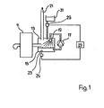
- reference number 11 denotes a boiler and reference number 13 an exhaust gas cleaning system.
- This consists essentially of a container 15, a circulating pump 17 and a spray device 19.
- the exhaust gases from the boiler 11 are therefore guided by a spray rain before they escape from the exhaust gas purification system 13 through the chimney 21.
- a pH sensor 23 is connected to a circuit 25 which supplies a signal corresponding to the measured pH to a control circuit 27. At a predetermined pH value, this delivers a signal for actuating the metering device 29 in order to conduct neutralizing agent from a container 31 into the washing container 15.
- a pH sensor 23 such as may be an exhaust gas washing device, such as is for example shown in Figure 1 used in '.
- two electrodes 35, 37 are attached to a central plate 33 made of insulating material, for example made of glass fiber reinforced plastic. These electrodes 35, 37 consist of a metal, for example stainless steel.
- the electrode 37 serves as a reference electrode and is located inside a cell 39.
- the electrode 35 serves as a measuring electrode and is arranged outside the cell 39, where it can be brought into contact with the liquid to be tested.
- the cell 39 contains an aqueous mass containing calcium carbonate and calcium sulfate.
- the cell 39 is formed by the middle plate 33 and a wall 41 made of plastic.
- the wall 41 consists, for example, of polyurethane and is firmly connected to the central plate 33.
- openings 43 in which diaphragms 45, for example made of ceramic material, preferably made of porcelain, are inserted.
- the electrodes 35, 37 are connected in the base 47 to the connecting cable 49, which leads to a circuit 25.
- E o has values from -20 to +20 mV for various sensors.
- the load capacity of the described pH sensor 23 is small. It is of the order of magnitude of a maximum of 10 nA.
- the circuit 25 must be designed so that it can eliminate disturbances from the environment and the measurement load remains sufficiently small. It should have a stabilizing effect on the pH sensor 23. For this purpose, it applies a feedback voltage to the measuring electrode 35 which corresponds to the voltage of the sensor which it has at the working pH.
- the sensor 23 described has the property that when solid particles of the neutralizing agent, for example Ca (OH) 2 , hit the measuring electrode 35, there is a rapid change in the potential difference. This change is determined by the circuit 25.
- the neutralizing agent for example Ca (OH) 2
- the output signal of the circuit 25 is fed to the control circuit 27, which actuates the dosing device 29 when a predetermined pH value is reached in order to switch on or off the supply of neutralizing agent.
- the control circuit 27 actuates the dosing device 29 when a predetermined pH value is reached in order to switch on or off the supply of neutralizing agent.
- precise control of the supply of neutralizing agent is effected. Overdosing can thus be avoided and optimal utilization of the neutralizing agent can be ensured.
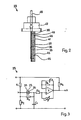
- the circuit 25 shown in FIG. 3 has a voltage divider with the resistors R 1 and R 2 .
- the center tap M of the voltage divider R 1 , R 2 is connected to the reference electrode 37 of the pH sensor 23.
- the measuring electrode 35 of the sensor 23 is connected via the resistor R 4 to the non-inverting input of an amplifier V, for example an operational amplifier.
- Resistor R 3 is connected in parallel with pH sensor 23.
- a capacitor C 1 is connected between the measuring electrode 35 and ground.
- a potentiometer P leads to the non-inverting input of operational amplifier V.
- an RC element consisting of resistor R 5 and capacitor C 2 , which are connected in parallel, leads to the inverting input of Operational amplifier V.
- a load resistor R 6 is connected to the output of the operational amplifier.
- the invention is not restricted to the exemplary embodiments described.
- the one described is also conceivable Circuit for pH sensors of a slightly different design.
Landscapes
- Chemical & Material Sciences (AREA)
- Life Sciences & Earth Sciences (AREA)
- Health & Medical Sciences (AREA)
- Physics & Mathematics (AREA)
- Chemical Kinetics & Catalysis (AREA)
- Electrochemistry (AREA)
- Molecular Biology (AREA)
- Analytical Chemistry (AREA)
- Biochemistry (AREA)
- General Health & Medical Sciences (AREA)
- General Physics & Mathematics (AREA)
- Immunology (AREA)
- Pathology (AREA)
- Treating Waste Gases (AREA)
Description
- Die Erfindung betrifft eine Vorrichtung zur Ueberwachung von Neutralisationsprozessen, mit einem pH-Sensor und einer an diesen angeschlossenen Schaltung, wobei der pH-Sensor eine electrochemische Zelle, eine in der Zelle enthaltene wässrige Masse, ein in der Wandung der Zelle angeordnetes Diaphragma, eine in der Zelle angeordnete Referenzelektrode und eine ausserhalb der Zelle angeordnete Messelektrode aufweist.
- Zur pH-Messung werden üblicherweise als Sensoren oder Fühler sogenannte Glaselektroden verwendet, bei denen eine dünne, für Wasserstoffionen durchlässige Glasmembran eine in einer Zelle angeordnete Referenzelektrode von einer ausserhalb dieser Zelle sich befindlichen Messelektrode trennt. In der Zelle befindet sich eine wässrige Masse bekannter Zusammensetzung, z.B. Calomel. Es hat sich gezeigt, dass solche pH-Sensoren nicht über längere Zeit wartungsfrei fünktionieren und dass grosse Messfehler auftreten können, wenn das zu messende Medium Feststoffteilchen enthält. Durch diese werden die Membranen der Sensoren nach kurzer Zeit verstopft bzw. zerstört. Bei Anlagen zur Nassreinigung von Abgasen bei Feuerungsanlagen ist aber mit Feststoffteilen in der Waschflüssigkeit zu rechnen, und es wird auch ein wartungsfreier Betrieb über längere Zeit gefordert.
- Die Stand der Technik bildende FR-A-2 354 558 beschreibt eine Vorrichtung zum Feststellen von Ionen in Flüssigkeiten. Als Mess- und Referenzelektroden dienen Glaselektroden. Die Referenzelektrode befindet sich in einem Raum zwischen zwei konzentrischen elektrisch isolierenden Hüllen, zwischen welche sich eine gelierte Referenzflüssigkeit befindet. Der die Referenzflüssigkeit enthaltende Raum ist mittels einer Dichtung abgeschlossen, welche eine ionendurchlässige Verbindung zwischen der Referenzflüssigkeit und der zu prüfenden Flüssigkeit bildet. Neben der Messelektrode befindet sich ein piezoelektrischer Wandler zur Erzeugung von Ultraschall-Vibrationen zur Reinigung der aktiven Flächen. Eine elektrische Schaltung für die Verstärkung der schwachen Ausgangssignale der hochvolumigen Glaselektroden ist innerhalb der innersten Hülle der Vorrichtung eingegossen. Diese Vorrichtung hat ebenfalls die eingangs erwähnten Nachteile der Glaselektroden. Um den Nachteil der kurzen Lebensdauer der Glaselektroden zu lindern, wird in der FR-A-2 354 558 weiter vorgeschlagen, drei oder mehr Glaselektroden als Messelektroden vorzusehen und mittels einer Vergleichschaltung diese zu überwachen. Bei der Feststellung eines Unterschieds löst die Vergleichschaltung einen Alarm aus. Die Messung wird dann bis zum Auswechseln der Vorrichtung von den verbleibenden intakten Glaselektroden weitergeführt. Es ist offensichtlich, dass sich eine solche Vorrichtung nicht zur Ueberwachung einer Anlage eignet, die über längere Zeit wartungsfrei arbeiten muss, wie dies beispielsweise eine für die Heizungsanlage eines Wohnhauses konzipierte Rauchgaswaschanlage der Fall ist.
- Die DE-OS 31 12 997 sieht eine Rauchgaswaschanlage vor, mit welcher das Kohlendioxid und das Schwefeldioxid des Rauchgases durch Wasser ausgewaschen wird. Das Waschwasser wird chemisch neutralisiert und danach wieder zur Rauchgaswäsche verwendet. Zu diesem Zweck ist unter anderem ein Neutralisationsbehälter vorgesehen, der einen pH-Wert-Regler aufweist, welcher mit einem Dosierventil verbunden ist, das zwischen dem Laugenbehälter und dem Neutralisationsbehälter angeordnet ist. Solche Rauchgas- oder Abgaswaschanlagen haben sich jedoch nicht bewährt, weil die in der Praxis verwendeten pH-Sensoren nicht über längere Zeit zuverlässig arbeiten. Die Gründe für das Versagen der handelsüblichen pH-Sensoren bei der Nassreinigung von Abgasen sind bisher weitgehend unbekannt geblieben.
- Wegen der Probleme mit den Sensoren wurden andere Wege gesucht, um einen geeigneten pH-Wert in der Waschflüssigkeit aufrecht zu erhalten. So geht beispielsweise die europäische Patentanmeldung 0 152 742 von der Tatsache aus, dass bei der Verbrennung von einem Kilogramm Heizöl 0,8 Liter Wasser entstehen, das kondensiert und in einem Behälter gesammelt werden kann. Die zitierte Anmeldung sieht eine Steuereinrichtung vor, um beim Erreichen eines vorbestimmten Wasserniveaus das Ablassen einer vorbestimmten Menge von Wasser zu steuern und zusätzlich eine Dosieranlage zu betätigen, die eine vorbestimmte Menge eines Neutralisationsmittels in die zum Waschen verwendete Flüssigkeit abgibt. Es hat sich aber gezeigt, dass auf diese Weise keine genaue Steuerung des pH-Werts erzielt werden kann. Ist aber der pH-Wert zu klein, so leidet darunter die Reinigungswirkung der Anlage. Darüber hinaus besteht die Gefahr, dass die saure Waschflüssigkeit korrodierend auf die Waschanlage einwirkt. Ist jedoch der pH-Wert zu gross, so steigt auch der Verbrauch an Neutralisationsmittel. Da bei der beschriebenen Anlage Flüssigkeit in die Kanalisation abgegeben wird, besteht zudem die Gefahr, dass dadurch die Funktion der Kläranlage gestört wird. So wird der biologische Abbau sowohl durch zu stark alkalische als auch durch zu stark saure Abwässer gestört. Dazu kommt noch erschwerdend hinzu, dass saure Abwässer meist auch grosse Mengen an Schwermetallen enthalten, die von korrodierten Anlageteilen stammen. Bei Abgaswaschanlagen kann nämlich eine saure Waschflüssigkeit Schwermetalle aus den zumeist aus rostfreiem Stahl bestehenden Anlageteilchen lösen.
- Es ist daher Aufgabe der vorliegenden Erfindung, eine Vorrichtung zur Ueberwachung von Neutralisationsprozessen zu schaffen, die die Nachteile der im Handel erhältlichen Vorrichtungen zur Messung des pH-Werts nicht aufweist und sich insbesondere zur Ueberwachung des pH-Werts der Waschflüssigkeit bei Abgasreinigungsanlagen eignet. Die Vorrichtung soll insbesondere lange Zeit wartungsfrei arbeiten und nicht z.B. durch in der Flüssigkeit enthaltene Feststoffe, wie z.B. Kalziumkarbonat oder Kalziumsulfat, beeinträchtigt werden.
- Gemäss der Erfindung wird dies bei einer Vorrichtung der eingangs erwähnten Art dadurch erreicht, dass die in der Zelle enthaltene wässrige Masse Kalziumsulfat und Kalziumkarbonat enthält, dass die Elektroden aus Metall bestehen, und dass zwecks Unterstützung der Ausbildung eines Puffersystems im pH-Sensor und der Stabilisierung des pH-Sensors die Schaltung einen Verstärker enthält, welcher an die Messelektrode eine Rückführspannung anlegt, die der Spannung entspricht, welche der pH-Sensor beim gewünschten Arbeits-pH-Wert aufweist. Da die in der Zelle enthaltene wässrige Masse die gleichen Stoffe enthält, die auch in der Flüssigkeit, deren pH-Wert zu prüfen ist, enthalten sind, verläuft im Betrieb die Alterung bei beiden Elektroden gleich, so dass der pH-Sensor während einer relativ langen Lebensdauer weitgehend stabil bleibt. Die Schaltung verhindert einerseits, dass der pH-Sensor ` z.B. durch auftretende elektrische Felder in der Messflüssigkeit nachhaltig gestört wird, und andererseits unterstützt sie die Ausbildung des nachstehend beschriebenen Puffersystems. Es hat sich gezeigt, dass die in der Zelle enthaltenen Stoffe auf das Metall der Referenzelektrode einwirken. So wird vermutet, dass das Kalziumkarbonat an der Oberfläche der Referenzelektrode ein Metallkarbonat bildet, welches am Aufbau eines Puffersystems (pH 9,5) in der Zelle mitwirkt. An der Messelektrode hingegen kommt die zu messende Wasserstoffionenkonzentration zur Wirkung, so dass über beiden Elektroden eine pH-Wert-abhängige elektrische Spannung entsteht. Im Ausführungsbeispiel bestehen die Elektroden aus einem Edelstahl, und es dürfte sich an der Referenzelektrode Eisenkarbonat bilden.
- Im Betrieb der Vorrichtung erfolgt beim Auftreten von Feststoffteilchen aus Kalziumhydroxid an der Messelektrode sehr rasch eine grosse Aenderung der Potentialdifferenz. Dieses empfindliche Ansprechen auf solche Feststoffteilchen ist von besonderer Bedeutung, weil dadurch die Konzentration der festen Neutralisationsmittel in der Flüssigkeit gut unter Kontrolle gehalten werden kann. Dadurch wird eine Ueberdosierung sicher vermieden und eine optimale Ausnützung des Neutralisationsmittels gewährleistet.
- Vorteilhaft besteht das Diaphragma aus Keramik, z.B. porösem Porzellan. Porzellan besitzt sehr feine Poren, durch welche hindurch der Elektrolyt in der Zelle in Kontakt mit der Flüssigkeit ausserhalb der Zelle tritt. Dennoch besteht keine Gefahr, dass der Elektrolyt aus der Zelle ausgewaschen wird.
- Die Rückführspannung hat Einfluss auf die im Sensor ablaufenden elektrochemischen Vorgänge, indem sie die Ausbildung bzw. Regenerierung des Puffersystems nach massiver Störung, z.B. Austrocknung, falsche Anwendung, elektrische Umladung etc., unterstützt und dadurch einen wichtigen Beitrag zur Langzeitstabilität des Sensors liefert. Durch die beschriebene Ausgestaltung der Schaltung wird somit eine äusserst stabil arbeitende Vorrichtung zur Bestimmung des pH-Werts geschaffen.
- Die Schaltung ist vorteilhaft so ausgebildet, dass der Ausgang des Verstärkers über ein Potentiometer mit dem nicht-invertierenden Eingang des Verstärkers verbunden ist, dass eine Elektrode des pH-Sensors an eine Stromquelle und die andere Elektrode über einen Widerstand an den nicht-invertierenden Eingang des Verstärkers angeschlossen sind, und dass parallel zum pH-Sensor ein Widerstand geschaltet ist, der in der Grössenordnung des inneren Widerstandes des Sensors liegt. Die Schaltung erzeugt über dem parallel zum Sensor geschalteten Widerstand eine Spannung gegen die Stromquelle. Diese wird Rückführspannung genannt und entspricht der Spannung des Sensors beim gewünschten Arbeits-pH-Wert. Die erforderliche Rückführspannung kann mit dem Potentiometer eingestellt werden.
- Der Ausgang des Verstärkers ist über ein RC-Glied an den invertierenden Eingang des Verstärkers angeschlossen. Dies bewirkt, dass die Ausgangsspannung des Verstärkers der Sensorspannung folgt während hochfrequente Störsignale unterdrückt werden.
- Zweckmässigerweise ist ein Spannungsteiler vorgesehen, dessen Mittelabzapfung an die Elektrode des pH-Sensors angeschlossen ist. Dadurch ergibt sich eine einfache und zweckmässige Energieversorgung des Verstärkers. Zweckmässigerweise ist ein Lastwiderstand an den Ausgang eines geeigneten Operationsverstärkers angeschlossen. Dies ermöglicht eine Anpassung der Inpedanz des Verstärkerausgangs. Vorteilhaft ist zwischen der Messelektrode des Sensors und der Masse der Schaltung ein Kondensator geschaltet. Dieser leitet hochfrequente Signale ab und trägt so zur Stabilisierung der Vorrichtung bei.
- Die Erfindung betrifft auch die Verwendung der Vorrichtung zur Kontrolle des pH-Werts der Waschflüssigkeit einer Abgasreinigungsanlage, insbesondere einer solchen bei einer Feuerungsanlage. Der Waschflüssigkeit einer solchen Abgasreinigungsanlage wird als Neutralisationsmittel vorteilhaft Kalziumoxid oder Kalziumhydroxid zugegeben. Dabei wird der pH-Wert der Waschflüssigkeit zweckmässigerweise im Bereich von 6 bis 6,8 gehalten. Damit wird erreicht, dass praktisch nur Kalziumsulfat aus der Waschflüssigkeit ausgeschieden wird. Es kommt also praktisch nicht zur Bildung von Kalziumkarbonat. Dies heisst mit anderen Worten, dass in erster Linie der Schwefelanteil aus dem Abgas abgeschieden wird, nicht aber der CO2-Anteil. Auf diese Weise wird eine erhebliche Einsparung an Neutralisationsmittel erreicht. Darüber hinaus werden Kalkablagerungen in der Waschanlage praktisch verhindert, und es fällt als Neutralisationsprodukt nur relativ wenig Kalziumsulfat an, also eine harmlose Substanz, die besser unter dem Namen Gips bekannt ist.
- Die Erfindung wird nun unter Bezugnahme auf die Zeichnung beschrieben. Es zeigt:
- Fig. 1 schematisch eine Heizanlage mit einer Abgasreinigungsanlage,
- Fig. 2 ein Ausführungsbeispiel eines pH-Sensors und
- Fig. 3 ein Ausführungsbeispiel einer zusammen mit dem pH-Sensor von Figur 2 verwendeten Schaltung.
- Bei der schematischen Darstellung von Figur 1 ist mit der Bezugsziffer 11 ein Heizkessel und mit der Bezugsziffer 13 eine Abgas-Reinigungsanlage bezeichnet. Diese besteht im wesentlichen aus einem Behälter 15, einer Umwälzpumpe 17 und einer Sprühvorrichtung 19. Die Abgase des Kessels 11 werden also durch einen Sprühregen geführt, bevor sie aus der Abgasreinigungsanlage 13 durch den Schornstein 21 entweichen. Ein pH-Sensor 23 ist an eine Schaltung 25 angeschlossen, welche ein dem gemessenen pH-Wert entsprechendes Signal an eine Steuerschaltung 27 liefert. Diese liefert bei einem vorbestimmten pH-Wert ein Signal zur Betätigung der Dosiervorrichtung 29, um aus einem Behälter 31 Neutralisationsmittel in den Waschbehälter 15 zu leiten.
- Figur 2 zeigt nun einen pH-Sensor 23, wie er bei 'einer Abgas-Wascheinrichtung, wie sie beispielsweise in Figur 1 dargestellt ist, verwendet werden kann. Bei diesem pH-Sensor oder Fühler 23 sind auf einer Mittelplatte 33 aus isolierendem Material, z.B. aus glasfaserverstärktem Kunststoff, zwei Elektroden 35, 37 angebracht. Diese Elektroden 35, 37 bestehen aus einem Metall, z.B. aus Edelstahl. Die Elektrode 37 dient als Referenzelektrode und befindet sich innerhalb einer Zelle 39. Die Elektrode 35 dient als Messelektrode und ist ausserhalb der Zelle 39 angeordnet, wo sie mit der zu prüfenden Flüssigkeit in Kontakt gebracht werden kann. Die Zelle 39 enthält eine wässrige Masse, die Kalziumkarbonat und Kalziumsulfat enthält. Die Zelle 39 wird durch die Mittelplatte 33 und eine Wandung 41 aus Kunststoff gebildet. Die Wandung 41 besteht beispielsweise aus Polyurethan und ist mit der Mittelplatte 33 fest verbunden. In der Wandung 41 befinden sich Oeffnungen 43, in denen Diaphragmen 45, z.B. aus keramischem Material, vorzugsweise aus Porzellan, eingesetzt sind. Die Elektroden 35, 37 sind im Sockel 47 mit dem Anschlusskabel 49 verbunden, das zu einer Schaltung 25 führt.
- Befindet sich der untere Teil des Sensors 23 in einer Flüssigkeit, z.B. der Waschflüssigkeit einer Abgasreinigungsanlage 13 (Fig. 1), dann entsteht über den Elektroden 35, 37 nach einer gewissen Einlaufzeit eine stabile Potentialdifferenz, die vom pH-Wert der Flüssigkeit abhängig ist. Diese Potentialdifferenz gehorcht der nachstehenden Formel:

- Eo besitzt für verschiedene Sensoren Werte von -20 bis +20 mV.
- Die Belastbarkeit des beschriebenen pH-Sensors 23 ist klein. Sie liegt in der Grössenordnung von maximal 10 nA. Infolgedessen muss die Schaltung 25 so konzipiert sein, dass sie Störungen aus dem Umfeld eliminieren kann und die Messbelastung ausreichend klein bleibt. Sie soll auf den pH-Sensor 23 stabilisierend einwirken. Zu diesem Zweck legt sie an die Messelektrode 35 eine Rückführspannung an, die derjenigen Spannung des Sensors entspricht, welche er beim Arbeits-pH aufweist.
- Der beschriebene Sensor 23 hat die Eigenschaft, dass beim Auftreffen von Feststoffteilchen des Neutralisationsmittels, z.B. Ca(OH)2, an der Messelektrode 35 rasch eine grosse Aenderung der Potentialdifferenz entsteht. Diese Aenderung wird durch die Schaltung 25 festgestellt.
- Wie Figur 1 zeigt, wird das Ausgangssignal der Schaltung 25 der Steuerschaltung 27 zugeführt, welche beim Erreichen eines vorbestimmten pH-Werts die Dosiervorrichtung 29 betätigt, um die Zufuhr von Neutralisationsmittel anzustellen bzw. abzustellen. Auf diese Weise wird eine genaue Steuerung der Neutralisationsmittelzufuhr bewirkt. Es kann also eine Ueberdosierung vermieden und eine optimale Ausnützung des Neutralisationsmittels gewährleistet werden.
- Die in Figur 3 gezeigte Schaltung 25 weist einen Spannungsteiler mit den Widerständen R1 und R2 auf. Die Mittelanzapfung M des Spannungsteilers R1, R2 ist mit der Referenzelektrode 37 des pH-Sensors 23 verbunden. Die Messelektrode 35 des Sensors 23 ist über den Widerstand R4 an den nicht-invertierenden Eingang eines Verstärkers V, z.B. eines Operationsverstärkers, angeschlossen. Parallel zum pH-Sensor 23 ist der Widerstand R3 geschaltet. Ein Kondensator C1 ist zwischen Messelektrode 35 und Masse geschaltet.
- Vom Ausgang des Operationsverstärkers V führt ein Potentiometer P zum nicht-invertierenden Eingang des Operationsverstärkers V. Vom Ausgang des Operationsverstärkers V führt ferner ein RC-Glied bestehend aus dem Widerstand R5 und dem Kondensator C2, die parallel geschaltet sind, zum invertierenden Eingang des Operationsverstärkers V. Ein Lastwiderstand R6 ist an den Ausgang des Operationsverstärkers angeschlossen.
- Der Operationsverstärker V ist vom Typ mit offenem Kollektor. Die einzelnen Elemente der Schaltung haben beispielsweise folgende Werte:
- R1 5,6 k0
- R2 5,6 kΩ
- R3 4,7 MΩ
- R4 2,2 MQ
- R5 10 MΩ
- R6 10 kΩ
- C, 0,1 uF
- C2 0,1 µF
- P 1 MΩ
- Die Erfindung ist nicht auf die beschriebenen Ausführungsbeispiele beschränkt. So ist es beispielsweise möglich, anstelle der beschriebenen Ausführungsbeispiele der Schaltung 25 eine andere geeignete Schaltung zu verwenden. Des weiteren ist auch denkbar, die beschriebene Schaltung für pH-Sensoren etwas anderer Bauart zu benützen.
Claims (13)
Priority Applications (1)
| Application Number | Priority Date | Filing Date | Title |
|---|---|---|---|
| AT87810223T ATE57012T1 (de) | 1986-04-21 | 1987-04-08 | Vorrichtung zur ueberwachung von neutralisationsprozessen und verwendung der vorrichtung bei abgasreinigungsanlagen. |
Applications Claiming Priority (2)
| Application Number | Priority Date | Filing Date | Title |
|---|---|---|---|
| CH1635/86 | 1986-04-21 | ||
| CH163586 | 1986-04-21 |
Publications (2)
| Publication Number | Publication Date |
|---|---|
| EP0243309A1 EP0243309A1 (de) | 1987-10-28 |
| EP0243309B1 true EP0243309B1 (de) | 1990-09-26 |
Family
ID=4215063
Family Applications (1)
| Application Number | Title | Priority Date | Filing Date |
|---|---|---|---|
| EP19870810223 Expired - Lifetime EP0243309B1 (de) | 1986-04-21 | 1987-04-08 | Vorrichtung zur Ueberwachung von Neutralisationsprozessen und Verwendung der Vorrichtung bei Abgasreinigungsanlagen |
Country Status (3)
| Country | Link |
|---|---|
| EP (1) | EP0243309B1 (de) |
| AT (1) | ATE57012T1 (de) |
| DE (1) | DE3765162D1 (de) |
Families Citing this family (1)
| Publication number | Priority date | Publication date | Assignee | Title |
|---|---|---|---|---|
| EP1491519A1 (de) | 2003-06-25 | 2004-12-29 | Mettler-Toledo GmbH | Verfahren zur Behandlung einer porösen Keramik |
Family Cites Families (3)
| Publication number | Priority date | Publication date | Assignee | Title |
|---|---|---|---|---|
| US3440518A (en) * | 1966-10-24 | 1969-04-22 | Beckman Instruments Inc | Voltage-to-current converter for use with measuring instruments |
| US4133732A (en) * | 1976-06-10 | 1979-01-09 | Jan Boeke | Combination electrode system |
| US4404065A (en) * | 1980-01-14 | 1983-09-13 | Enviromental Sciences Associates, Inc. | Electrochemical detection system and method of analysis |
-
1987
- 1987-04-08 DE DE8787810223T patent/DE3765162D1/de not_active Expired - Lifetime
- 1987-04-08 EP EP19870810223 patent/EP0243309B1/de not_active Expired - Lifetime
- 1987-04-08 AT AT87810223T patent/ATE57012T1/de not_active IP Right Cessation
Also Published As
| Publication number | Publication date |
|---|---|
| DE3765162D1 (de) | 1990-10-31 |
| EP0243309A1 (de) | 1987-10-28 |
| ATE57012T1 (de) | 1990-10-15 |
Similar Documents
| Publication | Publication Date | Title |
|---|---|---|
| DE69514106T2 (de) | Resistiver gassensor insbesondere zur detektion von ozon | |
| DE69534714T2 (de) | Verfahren und vorrichtung zum steuern der zufuhr von wasserbehandlungschemikalien unter verwendung eines voltametrischen sensors | |
| EP0103109B1 (de) | Verfahren zur Bestimmung der Zuckerkonzentration | |
| DE69121473T2 (de) | Strommessung mit Entfernen der galvanischen Schicht an den Elektroden einer Zelle | |
| DE2137073A1 (de) | Vorrichtung und Verfahren zur Be Stimmung der Elektroaktivitat eines wass rigen Musters | |
| DE3689539T2 (de) | Verfahren und Vorrichtung zur Betätigung einer elektrochemischen Messzelle. | |
| DE19959005A1 (de) | Verfahren und Vorrichtung zur Öl-in-Wasser Messung | |
| DE3405431A1 (de) | Messsonde zu potentiometrischer messung von ionenkonzentrationen, verfahren zu deren herstellung und ihre verwendung | |
| DE2434318C3 (de) | Einrichtung zur Messung der Ionenkonzentration in Flüssigkeiten | |
| WO1990001696A1 (de) | Verfahren und vorrichtungen zur bestimmung oxidierbarer wasserinhaltsstoffe einer wässrigen probenflüssigkeit | |
| DE2503176A1 (de) | Ionenselektive elektrode | |
| DE2265200C3 (de) | Strömungszelle für Zwecke der elektrochemischen Analyse | |
| DE2147725A1 (de) | Vorrichtung zum Bestimmen des Sauerstoffbedarfs in Flüssigkeitsproben | |
| EP0243309B1 (de) | Vorrichtung zur Ueberwachung von Neutralisationsprozessen und Verwendung der Vorrichtung bei Abgasreinigungsanlagen | |
| EP0282441B1 (de) | Verfahren zur Bestimmung des chemischen Sauerstoffbedarfs von Wasser | |
| DE69322850T2 (de) | Sauerstoffanalysegerät | |
| DE3546409A1 (de) | Verfahren und vorrichtung zur selbsttaetigen kalibrierung von chemischen sensoren | |
| EP0780685A1 (de) | Amperometrischer Zweielektrodensensor, insbesondere für Wasserstoffperoxid | |
| DE1598597A1 (de) | Elektrolytische Titrieranlage | |
| CH671710A5 (en) | Circulated boiler fume wash liq. is kept acidic - by controlling lime addn. to prevent carbonate formation | |
| DE1598597B2 (de) | Elektrolytische Titrieranlage | |
| EP0603751B1 (de) | Verfahren zum Nachweisen von Verbindungen, die in einer mindestens einen Feststoff enthaltenden flüssigen Phase vorliegen. | |
| DE2843885A1 (de) | Verfahren zum messen der konzentration von natrium in einem strom von quecksilbernatriumamalgam | |
| DE3345783C2 (de) | Verfahren zur Neutralisation von wäßrigen Lösungen | |
| DE2135949A1 (de) | Verfahren und Vorrichtung zum Bestimmen des Sauerstoffbedarfs wasseriger Proben |
Legal Events
| Date | Code | Title | Description |
|---|---|---|---|
| PUAI | Public reference made under article 153(3) epc to a published international application that has entered the european phase |
Free format text: ORIGINAL CODE: 0009012 |
|
| AK | Designated contracting states |
Kind code of ref document: A1 Designated state(s): AT BE CH DE ES FR GB GR IT LI LU NL SE |
|
| 17P | Request for examination filed |
Effective date: 19870930 |
|
| 17Q | First examination report despatched |
Effective date: 19890602 |
|
| GRAA | (expected) grant |
Free format text: ORIGINAL CODE: 0009210 |
|
| AK | Designated contracting states |
Kind code of ref document: B1 Designated state(s): AT BE CH DE ES FR GB GR IT LI LU NL SE |
|
| PG25 | Lapsed in a contracting state [announced via postgrant information from national office to epo] |
Ref country code: SE Effective date: 19900926 Ref country code: NL Effective date: 19900926 Ref country code: GR Free format text: LAPSE BECAUSE OF FAILURE TO SUBMIT A TRANSLATION OF THE DESCRIPTION OR TO PAY THE FEE WITHIN THE PRESCRIBED TIME-LIMIT Effective date: 19900926 |
|
| REF | Corresponds to: |
Ref document number: 57012 Country of ref document: AT Date of ref document: 19901015 Kind code of ref document: T |
|
| REF | Corresponds to: |
Ref document number: 3765162 Country of ref document: DE Date of ref document: 19901031 |
|
| RAP2 | Party data changed (patent owner data changed or rights of a patent transferred) |
Owner name: FUELLEMANN PATENT AG |
|
| RIN2 | Information on inventor provided after grant (corrected) |
Free format text: HEIERLI, WERNER |
|
| REG | Reference to a national code |
Ref country code: CH Ref legal event code: PUE Owner name: FUELLEMANN PATENT AG |
|
| ITF | It: translation for a ep patent filed | ||
| ET | Fr: translation filed | ||
| PG25 | Lapsed in a contracting state [announced via postgrant information from national office to epo] |
Ref country code: ES Free format text: LAPSE BECAUSE OF FAILURE TO SUBMIT A TRANSLATION OF THE DESCRIPTION OR TO PAY THE FEE WITHIN THE PRESCRIBED TIME-LIMIT Effective date: 19910106 |
|
| GBT | Gb: translation of ep patent filed (gb section 77(6)(a)/1977) | ||
| NLV1 | Nl: lapsed or annulled due to failure to fulfill the requirements of art. 29p and 29m of the patents act | ||
| ITTA | It: last paid annual fee | ||
| PLBE | No opposition filed within time limit |
Free format text: ORIGINAL CODE: 0009261 |
|
| STAA | Information on the status of an ep patent application or granted ep patent |
Free format text: STATUS: NO OPPOSITION FILED WITHIN TIME LIMIT |
|
| 26N | No opposition filed | ||
| PGFP | Annual fee paid to national office [announced via postgrant information from national office to epo] |
Ref country code: SE Payment date: 19940426 Year of fee payment: 8 |
|
| EPTA | Lu: last paid annual fee | ||
| PGFP | Annual fee paid to national office [announced via postgrant information from national office to epo] |
Ref country code: GB Payment date: 19960322 Year of fee payment: 10 Ref country code: CH Payment date: 19960322 Year of fee payment: 10 |
|
| PGFP | Annual fee paid to national office [announced via postgrant information from national office to epo] |
Ref country code: LU Payment date: 19960401 Year of fee payment: 10 |
|
| PGFP | Annual fee paid to national office [announced via postgrant information from national office to epo] |
Ref country code: BE Payment date: 19960412 Year of fee payment: 10 |
|
| PGFP | Annual fee paid to national office [announced via postgrant information from national office to epo] |
Ref country code: AT Payment date: 19960426 Year of fee payment: 10 |
|
| PGFP | Annual fee paid to national office [announced via postgrant information from national office to epo] |
Ref country code: FR Payment date: 19960430 Year of fee payment: 10 |
|
| PGFP | Annual fee paid to national office [announced via postgrant information from national office to epo] |
Ref country code: DE Payment date: 19960531 Year of fee payment: 10 |
|
| PG25 | Lapsed in a contracting state [announced via postgrant information from national office to epo] |
Ref country code: LU Free format text: LAPSE BECAUSE OF NON-PAYMENT OF DUE FEES Effective date: 19970408 Ref country code: GB Effective date: 19970408 Ref country code: AT Effective date: 19970408 |
|
| PG25 | Lapsed in a contracting state [announced via postgrant information from national office to epo] |
Ref country code: LI Free format text: LAPSE BECAUSE OF NON-PAYMENT OF DUE FEES Effective date: 19970430 Ref country code: CH Free format text: LAPSE BECAUSE OF NON-PAYMENT OF DUE FEES Effective date: 19970430 Ref country code: BE Effective date: 19970430 |
|
| BERE | Be: lapsed |
Owner name: FULLEMANN PATENT A.G. Effective date: 19970430 |
|
| GBPC | Gb: european patent ceased through non-payment of renewal fee |
Effective date: 19970408 |
|
| REG | Reference to a national code |
Ref country code: CH Ref legal event code: PL |
|
| PG25 | Lapsed in a contracting state [announced via postgrant information from national office to epo] |
Ref country code: FR Free format text: LAPSE BECAUSE OF NON-PAYMENT OF DUE FEES Effective date: 19971231 |
|
| PG25 | Lapsed in a contracting state [announced via postgrant information from national office to epo] |
Ref country code: DE Free format text: LAPSE BECAUSE OF NON-PAYMENT OF DUE FEES Effective date: 19980101 |
|
| REG | Reference to a national code |
Ref country code: FR Ref legal event code: ST |
|
| PG25 | Lapsed in a contracting state [announced via postgrant information from national office to epo] |
Ref country code: IT Free format text: LAPSE BECAUSE OF NON-PAYMENT OF DUE FEES;WARNING: LAPSES OF ITALIAN PATENTS WITH EFFECTIVE DATE BEFORE 2007 MAY HAVE OCCURRED AT ANY TIME BEFORE 2007. THE CORRECT EFFECTIVE DATE MAY BE DIFFERENT FROM THE ONE RECORDED. Effective date: 20050408 |