EP0242671B1 - Bremse für einen Motor - Google Patents
Bremse für einen Motor Download PDFInfo
- Publication number
- EP0242671B1 EP0242671B1 EP87104974A EP87104974A EP0242671B1 EP 0242671 B1 EP0242671 B1 EP 0242671B1 EP 87104974 A EP87104974 A EP 87104974A EP 87104974 A EP87104974 A EP 87104974A EP 0242671 B1 EP0242671 B1 EP 0242671B1
- Authority
- EP
- European Patent Office
- Prior art keywords
- brake
- coil
- switch
- circuit
- motor
- Prior art date
- Legal status (The legal status is an assumption and is not a legal conclusion. Google has not performed a legal analysis and makes no representation as to the accuracy of the status listed.)
- Expired - Lifetime
Links
- 230000005284 excitation Effects 0.000 claims description 3
- 230000001133 acceleration Effects 0.000 description 6
- 239000003990 capacitor Substances 0.000 description 5
- XEEYBQQBJWHFJM-UHFFFAOYSA-N Iron Chemical compound [Fe] XEEYBQQBJWHFJM-UHFFFAOYSA-N 0.000 description 4
- 230000000903 blocking effect Effects 0.000 description 4
- 230000005669 field effect Effects 0.000 description 4
- 238000012544 monitoring process Methods 0.000 description 3
- 230000001934 delay Effects 0.000 description 2
- 230000004907 flux Effects 0.000 description 2
- 229910052742 iron Inorganic materials 0.000 description 2
- 238000000926 separation method Methods 0.000 description 2
- RYGMFSIKBFXOCR-UHFFFAOYSA-N Copper Chemical compound [Cu] RYGMFSIKBFXOCR-UHFFFAOYSA-N 0.000 description 1
- 239000003638 chemical reducing agent Substances 0.000 description 1
- 229910052802 copper Inorganic materials 0.000 description 1
- 239000010949 copper Substances 0.000 description 1
- 230000003111 delayed effect Effects 0.000 description 1
- 230000005347 demagnetization Effects 0.000 description 1
- 238000007599 discharging Methods 0.000 description 1
- 230000000694 effects Effects 0.000 description 1
- 238000005265 energy consumption Methods 0.000 description 1
- 238000010304 firing Methods 0.000 description 1
- 230000020169 heat generation Effects 0.000 description 1
- 230000006698 induction Effects 0.000 description 1
- 238000009434 installation Methods 0.000 description 1
- 238000005259 measurement Methods 0.000 description 1
- 230000003071 parasitic effect Effects 0.000 description 1
- 238000004804 winding Methods 0.000 description 1
Images


Classifications
-
- H—ELECTRICITY
- H02—GENERATION; CONVERSION OR DISTRIBUTION OF ELECTRIC POWER
- H02P—CONTROL OR REGULATION OF ELECTRIC MOTORS, ELECTRIC GENERATORS OR DYNAMO-ELECTRIC CONVERTERS; CONTROLLING TRANSFORMERS, REACTORS OR CHOKE COILS
- H02P3/00—Arrangements for stopping or slowing electric motors, generators, or dynamo-electric converters
- H02P3/02—Details of stopping control
- H02P3/04—Means for stopping or slowing by a separate brake, e.g. friction brake or eddy-current brake
-
- H—ELECTRICITY
- H02—GENERATION; CONVERSION OR DISTRIBUTION OF ELECTRIC POWER
- H02K—DYNAMO-ELECTRIC MACHINES
- H02K7/00—Arrangements for handling mechanical energy structurally associated with dynamo-electric machines, e.g. structural association with mechanical driving motors or auxiliary dynamo-electric machines
- H02K7/10—Structural association with clutches, brakes, gears, pulleys or mechanical starters
- H02K7/102—Structural association with clutches, brakes, gears, pulleys or mechanical starters with friction brakes
- H02K7/1021—Magnetically influenced friction brakes
- H02K7/1023—Magnetically influenced friction brakes using electromagnets
Definitions
- the invention relates to a brake for a motor, in particular an AC motor with an electromagnet and a rectifier circuit for the electromagnet.
- a brake for a motor in particular an AC motor with an electromagnet and a rectifier circuit for the electromagnet.
- an armature disk is usually moved against the force of springs when switched on
- large magnetomotive forces or flooding must be built up when switching on in order to move the armature disk, in particular a brief response of the brake to reach.
- the air gap between the armature disk and the electromagnet is smaller, and thus the magnetic resistance is reduced, so that less flooding and therefore lower holding currents are required to hold the brake.
- the invention has for its object to further develop a generic brake in such a way that the dynamic properties are improved in a simple manner.
- the inventive design of the brake improves the dynamic properties of a brake, which can initially be designed more cost-effectively, since both less copper for the winding and less iron for the armature and, moreover, cheaper iron can be used, which results in the small additional cost for switching electronics , which only switches a coil part on or off in the circuit, more than compensates.
- the brake has less wear and has a longer brake pad life, since the pad is less worn due to the high inrush current pulling the brake with electromagnetic generation of the release force. Because a short switch-on time is achieved due to the small time constant of the accelerator coil. A high current flows for a short time, but this does not lead to oversaturation due to the lower number of turns. In addition, even when starting off, the engine is warmed up less by quickly lifting the brake.
- a partial coil as an acceleration coil is in series with a switch arranged in parallel with the other partial coil, which switch can be switched by an assigned control element.
- This development according to the invention creates the possibility that the voltage is applied to only a part of the coil during the switching on of the brake and thus the current flows only through a part of the coil as a particularly large current sufficient for tightening the armature disk while holding the voltage drops over the entire coil, so that a lower holding current flows automatically due to the increased resistance.
- the control element is preferably designed as a time switching element, to which one of the sub-coils is also connected in series as a series resistor.
- the switch which is preferably connected as an electronic switch, such as a thyristor
- the rectified current flows through a coil part, namely the acceleration part coil, and the thyristor. Blocking the thyristor causes a current to flow through both sub-coils and thus the increased resistance to reduce the current flow.
- the coil or one of its branches is conventionally assigned a free-wheeling circuit with a free-wheeling diode. to reduce the magnetic energy of the coil after switching off.
- the freewheeling circuit is made high-impedance by blocking an electronic switch, so that the current flows after switching off via a resistor, such as a varistor, arranged in parallel with the switch.
- a resistor such as a varistor
- a current transformer is arranged in the voltage supply of the brake motor, which has a control circuit for one Switch arranged in the circuit of the brake coil is connected. According to the invention, therefore, for switching the magnet as the control signal for opening the free-wheeling circuit of the brake, it is not the voltage but the motor current which, in contrast to the voltage, is also interrupted immediately after the supply to the motor is interrupted, for example by switching a contactor, as a result of which the switch-off times can be further reduced.
- control circuit has a Schmitt trigger circuit and that the circuit breaker is assigned a diode in anti-parallel, the diode ensuring additional protection of the switch, in particular a field effect transistor, against reverse polarity.
- the invention further proposes countercurrent excitation, so that a preferred one Further development of the invention is characterized in that a counter-excitation branch with a switch for countercurrent application is assigned to the freewheeling circuit.
- a counter-excitation branch with a switch for countercurrent application is assigned to the freewheeling circuit.
- the residual induction voltage of the motor is used after it has been switched off, in order to apply the brake in countercurrent.
- the motor had no residual voltage after switching off, so that there would be no counteracting, this would correspond to switching off on the AC voltage, in which case the brake would apply quickly anyway due to its design according to the invention.
- the switch for carrying out the circuit belongs to a contactor with which the mains voltage is switched on and off, although this criticizes the fact that a motor contactor with an additional Switch contact for the brake coil and accordingly additional connecting lines from the contactor to the circuit arrangement for the brake coil are required, so that DC-side shutdowns due to the residual voltage of the motor, which have the disadvantages mentioned above, have been proposed.
- the invention provides an AC disconnection in that when the switching signal is received via a current transformer which is arranged in the voltage supply of the brake motor, the switch mentioned is connected to the voltage supply of the brake coil on the AC side.
- the switch is a circuit breaker and a triac is particularly suitable.
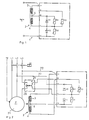
- the braking device according to the invention which is generally designated 1 in FIG. 1, has an electromagnet 2 with two sub-coils 3, 4 — shown schematically in FIG. 1. Between the two partial coils 3, 4 there is an intermediate tap 6.
- the overall coil 2 is preferably constructed such that the two partial coils are wound radially one above the other and the intermediate tap 6 is led out at a suitable point.
- the partial coil 3 has about half to 1/3 of the resistance of the partial coil 4. It is still one
- One-way rectifier circuit 7 with two rectifier diodes V1, V2 is provided, of which the diode V1 is arranged as a freewheeling diode parallel to the coil section 4.
- the diodes V1, V2, varistors R1 and R2 are connected in parallel as an overvoltage protection element.
- a third varistor R3 is provided, which is explained with reference to FIG. 2 and which, when the brake is switched off, lies in series with the high-resistance free-wheeling circuit of the brake coil, as a comparison with FIG
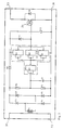
- FIG. 2 shows a motor 21 to be braked with connections L1, L2, L3 for the phases R, S, T of an AC voltage network.
- a motor contactor K1 is arranged in the connecting lines L1, L2, L3, via which the motor 21 can be connected to the network. Connections 22, 23 lead from two connection lines, here L2, L3, to the braking device of FIG. 1.
- a switch 24, which can be switched by switching off the network via contactor K1, is also provided in the freewheeling circuit of the release magnet 2. The switch 24 can be switched in a manner known per se by the voltage drop when the motor is switched off via the contactor K1 or by means of the control circuit 26 described in FIG. 3 in the manner also shown in FIG. 2 by the motor current.
- the switch 24 is already in the Figure 1 contained varistor R3 shunted.
- the switch 24 switched by the varistor R3 is opened and thus the freewheeling current flowing through the freewheeling diode V1 is reduced to a value limited by the varistor R3, so that the release magnet releases the brake 1 accordingly can occur even faster.
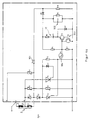
- the switch 24 in the freewheeling circuit of the release magnet can, as mentioned, continue to be part of a control circuit 26, as shown in FIG. 3.
- the circuit 26 of FIG. 3 as such is preferably designed as an additional device in a separate housing.
- the housing can be configured as described with reference to FIG. 7.
- the additional device having the circuit 26 has four connections. With two connections 31, 32 it is switched into one of the connection lines of the motor, in the exemplary embodiment shown in FIG. 2 into line L3.
- the circuit 26 initially has a current transformer T1 as an essential element, so that it detects the motor current and not the voltage applied to the motor 21.
- output terminals 33, 34 which are assigned to the electronic switch 24, which in the exemplary embodiment shown is a field effect transistor, the additional device is switched into the freewheeling circuit of the release magnet.
- An anti-parallel diode V8 can be connected to the switch 24 in order to ensure additional protection against reverse polarity when wiring. When using a field effect transistor, this has already integrated the diode (as a parasitic component).
- the control circuit 26 initially has a bridge rectifier 37 with two diodes V4, V5 and two Zener diodes Z1, Z2 - the latter for voltage limitation - and also a Schmitt trigger D1, which is formed by an integrated module 4093 with appropriate wiring. Furthermore, a filter element R4, R5, C1 is provided in order to filter out the ripple of the rectifier signal rectified by the rectifier.
- the Schmitt trigger D1 is supplied via the diodes V6 and the capacitor C2, which ensures that there is always a sufficient supply voltage available for the Schmitt trigger.
- V7 is a protection diode.
- FIG. 1 Another embodiment of the brake is described in FIG. This embodiment is based on FIG. 1, so that reference is made to the explanations given there with regard to the corresponding features.
- a thyristor Th which causes the coil section 3 to be switchable as an acceleration coil.
- the thyristor Th itself is switched, in particular fired, by a time switching element 12, which has an RC element (itself not shown) that applies the ignition signal to the thyristor Th for a desired time.
- a monitoring unit 13 is provided here for retriggering the time switch element 12 in the event of undervoltage, the use of which depends on the dimensioning of the brake and is explained in more detail below.
- the unit 13 preferably works on the principle of relative voltage measurement, so that the function of the device is independent of the supply voltage. Compared to the embodiment in FIG. 1, the dimensions of the coil and the partial coils 6 are such that, without switching, the current flowing through the entire coil 2 is no longer sufficient to apply the brake. In this embodiment, the same coil as in FIG. 1 can therefore be used for a "heavier" brake for a stronger motor.
- the function of the circuit shown in FIG. 4 is now basically as follows: When applying mains voltage and thus switching on the motor 21, the thyristor Th is turned on as an electronic switch, so that a large current flows through the acceleration coil 3 due to the small internal resistance compared to the total coil 2, which has a large magnetic flux and thus a fast pull-in effect and a short response time. After the brake magnet has responded, the high magnetic flux is no longer required, since the air gap between the armature and the solenoid coil and thus the magnetic resistance has been reduced. There are therefore lower holding forces, so that less magnetic flooding and lower holding currents are required.
- the thyristor Th is blocked by the timer 12, so that the mains current over the entire coil, that is, both partial coils 3, 4 flows, wherein it is rectified by the oppositely aligned diodes 8, 9 forming the rectifier. Due to the greater resistance of the overall coil 3, 4, a lower holding current flows, which enables lower energy consumption and faster shutdown when switched off.
- the braking device described above can be switched according to that of FIG. 1 in the manner shown in FIG. 2 for additional rapid shutdown by means of a freewheeling circuit switched through the varistor 3 with a high resistance.
- a counter-excitation can be provided for the rapid switch-off or rapid excitation of the brake coil, as is indicated in broken lines in FIG. 4.
- a further thyristor Th is arranged antiparallel to the thyristor Th, with which switching electronics corresponding to the electronics 12 (not shown in detail) is assigned.
- the thyristor Th switches the negative mains half-wave to the acceleration coil 3.
- the voltage comes from the motor, so that timing is not necessary.
- the counter current flow leads to the rapid demagnetization of the system and thus to the rapid application of the brake.
- the thyristor Th can be ignited in a suitable manner, for example by a current sensor T1 according to FIG. 3.
- the circuit replaces the control line and the switching contact of a “DC-side disconnection”, for example as in FIG. 2.
- the monitoring circuit 13 is fed from the network via a series resistor 101 of, for example, approximately 180 K and the brake coil 2.
- the relative voltage is taken on the one hand at a capacitor 102 with 0.33 uF and on the other hand at the timing element 12 with, for example, 220 K 0.1 uF.
- a double transistor arrangement 103 (which can be regarded as a thyristor) is first switched due to an occurring voltage difference, followed by a field effect transistor (FET) 104 in such a way that the thyristor Th is first switched on, so that the acceleration coil 3 alone between the network terminals.
- FET field effect transistor
- the firing pulse is removed from the thyristor Th so that it blocks.
- the voltage drops discharging takes place, so that the voltage difference occurs again when the voltage increases again.
- the other links are used for coordination for the respective application.
- the FET 104 When the FET 104 is turned on, there is no signal at the thyristor Th 2, which means that the thyristor Th can ignite on a positive half-wave. When the FET 104 blocks, an ignition signal is present at the thyristor Th 2, which makes it conductive in the event of a positive half-wave and thus removes the ignition voltage from the thyristor Th. At a certain voltage difference across the timing element 12 and the capacitor (102) in question, the double transistor 103 (thyristor) in question is turned on, causing the transistor 104 to conduct will (self-conducting FET) and the thyristor Th can ignite.
- FIG. 5 shows, in accordance with FIG. 2, the switching of a conventional brake by the current of the motor 21 by means of a circuit 26 according to FIG.
- the motor 21 with the connections L1, L2, L3 for the phases R, S, T of an AC voltage network and the motor contactor K1 arranged in the connecting line L1, L2, L3, via which the motor 21 can be connected to the network.
- the connections 22, 23 lead from the connecting lines L2 and L3 to a circuit arrangement 41, which, as said, is a conventional circuit arrangement in the embodiment of FIG.
- the circuit arrangement shown in FIG. 5 has a rectifier with two zero diodes in a one-way circuit. To control the high switch-off speeds of large inductors, the additional circuitry has been implemented with the varistor R3.
- the switch 24 shunted by the varistor R3 in the freewheeling circuit having a freewheeling diode in the coil of the brake 42 is opened, the freewheeling current flowing through the freewheeling diode is reduced to a value limited by the varistor R3, so that the release magnet can apply the brake 1 accordingly quickly.
- the circuit of FIG. 5 is known, provided that it has the control circuit 41 corresponding to the illustration in FIG. 5.
- switch 24 in the freewheeling circuit of the release magnet is now part of the control circuit 27 in FIG with their connections 31, 32 connected to the connecting line L3 of the motor 21 so that the switch 24 is switched here in the manner according to the invention by the motor current.
- the circuit of FIG. 3 is preferably designed as an additional device in a separate housing.
- the housing can be formed by standard components, such as a conventional screwing part and a blind plug, so that the additional device can be attached to the terminal box of the motor by screwing into the thread of a cable bushing, so that the use of a larger terminal box compared to conventional ones is unnecessary.
- the intermediate tap 6 according to the invention on the brake coil 2 and the arrangement of the free-wheeling circuit via the partial coil 4 with the free-wheeling diode V1 enables, instead of the previously preferred DC-side separation, a similar result by means of AC-side separation with less effort.
- a circuit 51 according to FIG. 6 is provided, which is connected with its connections 52 and 53 in a feed line L3 to the motor 21 similar to the circuit of FIG. With the outputs 54, 56, the circuit is switched on the AC side into one of the supply lines 22, 23 of the brake coil 2 (FIG. 2).
- the circuit 51 initially has a current transformer T11, which is followed by a rectifier with diodes V11, V12 and, for voltage limitation, Zener diodes V13, V14.
- a capacitor 10, 11 is provided to bridge the short-term voltage drop of the alternating signal.
- the voltage smoothed by the current transformer T11 and the capacitor C11 is applied to the control input of a triac V15, to which a varistor R11 is connected in parallel.
- the supply to the brake coil 2 is immediately interrupted by blocking the triac V15 via the current sensor T11 or reduced by the varistor R11 to a value which is not sufficient to hold the brake.
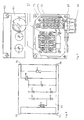
- FIG. 7 shows a structural design for accommodating additional circuits, in particular with current sensors, such as those in FIGS. 3 and 6, without the need for larger terminal boxes.
- a conventional terminal box 61 has, in addition to its cover 62, a series of cable bushings 63 which have an internal thread and are closed by blind plugs 64 provided with an external thread, provided they are not used.
- an additional housing 66 is screwed with a threaded extension 67, which is closed at the front with its cover 68.
- the additional housing is a reducer or expansion piece, into which an adapted blind plug is screwed in the front, with the interposition of seals, such as an O-ring (not shown in detail).
- a clamping plate is designated.
- the brake rectifier is located at 72.
- 73 denotes a terminal block.
- the cabling is not shown in detail.
Landscapes
- Engineering & Computer Science (AREA)
- Power Engineering (AREA)
- Physics & Mathematics (AREA)
- Electromagnetism (AREA)
- Stopping Of Electric Motors (AREA)
- Braking Arrangements (AREA)
- Connection Of Motors, Electrical Generators, Mechanical Devices, And The Like (AREA)
- Valve Device For Special Equipments (AREA)
- Transplanting Machines (AREA)
Priority Applications (1)
| Application Number | Priority Date | Filing Date | Title |
|---|---|---|---|
| AT87104974T ATE79204T1 (de) | 1986-04-19 | 1987-04-03 | Bremse fuer einen motor. |
Applications Claiming Priority (2)
| Application Number | Priority Date | Filing Date | Title |
|---|---|---|---|
| DE19863613294 DE3613294A1 (de) | 1986-04-19 | 1986-04-19 | Bremse fuer einen motor |
| DE3613294 | 1986-04-19 |
Publications (3)
| Publication Number | Publication Date |
|---|---|
| EP0242671A2 EP0242671A2 (de) | 1987-10-28 |
| EP0242671A3 EP0242671A3 (en) | 1989-05-17 |
| EP0242671B1 true EP0242671B1 (de) | 1992-08-05 |
Family
ID=6299084
Family Applications (1)
| Application Number | Title | Priority Date | Filing Date |
|---|---|---|---|
| EP87104974A Expired - Lifetime EP0242671B1 (de) | 1986-04-19 | 1987-04-03 | Bremse für einen Motor |
Country Status (9)
| Country | Link |
|---|---|
| EP (1) | EP0242671B1 (fi) |
| AT (1) | ATE79204T1 (fi) |
| AU (1) | AU602685B2 (fi) |
| BR (1) | BR8701854A (fi) |
| CA (1) | CA1290387C (fi) |
| DE (2) | DE3613294A1 (fi) |
| DK (1) | DK171091B1 (fi) |
| FI (1) | FI94688C (fi) |
| ZA (1) | ZA872751B (fi) |
Families Citing this family (16)
| Publication number | Priority date | Publication date | Assignee | Title |
|---|---|---|---|---|
| EP0993697B1 (de) | 1997-07-04 | 2003-10-15 | Sew-Eurodrive GmbH & Co. KG | Elektromotor und verfahren zum betreiben eines elektromotors |
| DE19730440A1 (de) * | 1997-07-16 | 1999-01-21 | Flender Himmelwerk Gmbh | Schaltgerät für elektromagnetisch betätigte Baugruppen |
| AU9265098A (en) * | 1997-08-25 | 1999-03-16 | Sew-Eurodrive Gmbh & Co | Method and circuit arrangement for operating an electromagnetically actuated mechanical brake of an electric motor |
| US5892341B1 (en) * | 1997-10-29 | 2000-06-27 | Rexnord Corp | Quick set electric motor brake control |
| DE19964437B4 (de) | 1999-02-24 | 2018-10-31 | Sew-Eurodrive Gmbh & Co Kg | Verteiler |
| DE102004013033B3 (de) | 2004-03-16 | 2005-07-14 | Sew-Eurodrive Gmbh & Co. Kg | Antrieb |
| DE102004022254B3 (de) * | 2004-05-04 | 2005-06-30 | Sew-Eurodrive Gmbh & Co. Kg | Spule |
| DE102005027502B4 (de) * | 2004-10-22 | 2009-07-09 | Sew-Eurodrive Gmbh & Co. Kg | Elektromagnetisch betätigbare Bremse, Vorrichtung zur sicheren Ansteuerung einer elektromagnetisch betätigbaren Bremse, Elektromotor und Bremse |
| DE102005030085B4 (de) * | 2005-06-27 | 2007-06-06 | Sew-Eurodrive Gmbh & Co. Kg | Vorrichtung und Verfahren zur Prüfung und/oder Überwachung einer elektromagnetisch betätigbaren Bremse sowie Elektromotor mit Vorrichtung |
| DE102006034049B4 (de) * | 2006-07-20 | 2014-08-07 | Sew-Eurodrive Gmbh & Co Kg | Elektromagnetisch betätigbare Bremse oder Kupplung mit Lüftspule, Verfahren zum Betreiben derselben und Antrieb |
| JP5164875B2 (ja) * | 2009-02-04 | 2013-03-21 | 株式会社日立製作所 | エレベーター用電磁ブレーキ制御装置 |
| DE102009007961A1 (de) * | 2009-02-06 | 2010-08-19 | Sew-Eurodrive Gmbh & Co. Kg | Antriebssystem und Verfahren zum Betreiben eines Antriebssystems |
| DE102010050346B4 (de) | 2009-11-26 | 2015-08-06 | Sew-Eurodrive Gmbh & Co Kg | Elektromagnetisch betätigbare Bremse und Verfahren zum Betreiben einer Bremse |
| DE102010014860B4 (de) | 2010-04-13 | 2018-12-20 | Sew-Eurodrive Gmbh & Co Kg | Spule und Bremse |
| DE102020213640A1 (de) * | 2020-10-29 | 2022-05-05 | Maha Maschinenbau Haldenwang Gmbh & Co. Kg | Entriegelung einer elektromagnetischen Bremse eines Motors |
| WO2023285060A1 (de) | 2021-07-12 | 2023-01-19 | Sew-Eurodrive Gmbh & Co. Kg | Antriebssystem mit zentralmodul, verteilern und antrieben |
Family Cites Families (5)
| Publication number | Priority date | Publication date | Assignee | Title |
|---|---|---|---|---|
| US3087104A (en) * | 1961-06-12 | 1963-04-23 | Gen Electric | Series brake system for alternating current motors |
| US3614565A (en) * | 1970-07-09 | 1971-10-19 | Harnischfeger Corp | Control for electromechanical brake |
| DE3045027C2 (de) * | 1980-11-28 | 1982-10-21 | Siemens AG, 1000 Berlin und 8000 München | Elektrische Schaltungsanordnung für einen Wechselstrommotor mit einer elektromagnetisch lüftbaren Federdruckbremse |
| DE3223260C2 (de) * | 1982-06-22 | 1984-10-25 | Eberhard Bauer Elektromotorenfabrik GmbH, 7300 Esslingen | Schaltungsanordnung zur Unterbrechung des Freilaufstromes für Lüftmagneten von Bremsmotoren |
| JPS6013484A (ja) * | 1983-07-01 | 1985-01-23 | Hitachi Ltd | 直流ブレ−キ付回転電機 |
-
1986
- 1986-04-19 DE DE19863613294 patent/DE3613294A1/de active Granted
-
1987
- 1987-04-03 DE DE8787104974T patent/DE3780850D1/de not_active Expired - Lifetime
- 1987-04-03 AT AT87104974T patent/ATE79204T1/de not_active IP Right Cessation
- 1987-04-03 EP EP87104974A patent/EP0242671B1/de not_active Expired - Lifetime
- 1987-04-10 FI FI871579A patent/FI94688C/fi not_active IP Right Cessation
- 1987-04-13 DK DK189087A patent/DK171091B1/da not_active IP Right Cessation
- 1987-04-14 CA CA000534642A patent/CA1290387C/en not_active Expired - Lifetime
- 1987-04-15 BR BR8701854A patent/BR8701854A/pt not_active IP Right Cessation
- 1987-04-16 AU AU71768/87A patent/AU602685B2/en not_active Ceased
- 1987-04-16 ZA ZA872751A patent/ZA872751B/xx unknown
Also Published As
| Publication number | Publication date |
|---|---|
| CA1290387C (en) | 1991-10-08 |
| DK171091B1 (da) | 1996-05-28 |
| EP0242671A2 (de) | 1987-10-28 |
| ATE79204T1 (de) | 1992-08-15 |
| ZA872751B (en) | 1987-10-06 |
| DE3613294A1 (de) | 1987-10-22 |
| AU602685B2 (en) | 1990-10-25 |
| DE3613294C2 (fi) | 1991-05-23 |
| DK189087D0 (da) | 1987-04-13 |
| DK189087A (da) | 1987-10-20 |
| FI94688B (fi) | 1995-06-30 |
| FI871579A0 (fi) | 1987-04-10 |
| DE3780850D1 (de) | 1992-09-10 |
| EP0242671A3 (en) | 1989-05-17 |
| BR8701854A (pt) | 1988-01-26 |
| FI871579A (fi) | 1987-10-20 |
| AU7176887A (en) | 1987-10-22 |
| FI94688C (fi) | 1995-10-10 |
Similar Documents
| Publication | Publication Date | Title |
|---|---|---|
| EP0242671B1 (de) | Bremse für einen Motor | |
| EP0006843B2 (de) | Magnetventil mit elektronischer Steuerung | |
| EP1527470B1 (de) | Steueranordnung für einen elektromagnetischen antrieb | |
| DE2546424C2 (fi) | ||
| DE3237823A1 (de) | Drehzahlsensor fuer das elektronische abbremsen eines motors | |
| DE2362472C3 (de) | Zündanlage mit Magnetgenerator für Brennkraftmaschinen | |
| DE2829828C2 (de) | Für eine Brennkraftmaschine bestimmte Zündanlage | |
| DE2235573A1 (de) | Elektronische treiberschaltung fuer halbleiterschalter | |
| DE3842883A1 (de) | Elektrische beleuchtungseinrichtung und insbesondere fuer diese geeignete schutzschaltung | |
| EP0534250B1 (de) | Verfahren und Vorrichtung zum Absichern eines Wechselstromkreises | |
| DE1438052B2 (de) | Elektrische anlage fuer kraftfahrzeuge | |
| EP0466738B1 (de) | Vorrichtung zur wechselstrom-einschaltbegrenzung | |
| DE1136767B (de) | Kontaktlose, verzoegert arbeitende Schalteinrichtung | |
| DE3506849C1 (de) | Elektrische Steuerschaltung | |
| DE3835869C2 (fi) | ||
| DE2246258C3 (de) | Schaltungsanordnung zur Gleichstromspeisung eines mit einer Freilaufdiode beschalteten Verbrauchers | |
| DE3438215A1 (de) | Anordnung zur ansteuerung von mehreren magnetventilen | |
| DD158156A5 (de) | Vom wechselstromnetz gespeister,in beiden drehrichtungen bremsbarer umkehrantrieb | |
| DE102020215711B4 (de) | Auslösevorrichtung für einen Leistungsschalter | |
| DE2711232C2 (de) | Verfahren zur Umschaltung von Straßenverkehrsanlagen von Tag- auf Nachtbetrieb | |
| DE3708250A1 (de) | Vorrichtung zum steuern der triggerfolge bei zuendsystemen | |
| EP0941550B1 (de) | Elektromagnet für magnetventil | |
| EP1107414B1 (de) | Verfahren zur Unterspannungs-Ueberwachung einer Netzspannung und Unterspannungsausloeser | |
| DE1613629A1 (de) | Verfahren zur Reduzierung von Netzeinbruechen oder Netzspannungserhoehungen,insbesondere bei Flugzeugbordnetzen | |
| DE3027183A1 (de) | Schaltungsanordnung |
Legal Events
| Date | Code | Title | Description |
|---|---|---|---|
| PUAI | Public reference made under article 153(3) epc to a published international application that has entered the european phase |
Free format text: ORIGINAL CODE: 0009012 |
|
| AK | Designated contracting states |
Kind code of ref document: A2 Designated state(s): AT BE CH DE ES FR GB GR IT LI LU NL SE |
|
| PUAL | Search report despatched |
Free format text: ORIGINAL CODE: 0009013 |
|
| AK | Designated contracting states |
Kind code of ref document: A3 Designated state(s): AT BE CH DE ES FR GB GR IT LI LU NL SE |
|
| RHK1 | Main classification (correction) |
Ipc: H02P 3/04 |
|
| 17P | Request for examination filed |
Effective date: 19890731 |
|
| 17Q | First examination report despatched |
Effective date: 19920116 |
|
| GRAA | (expected) grant |
Free format text: ORIGINAL CODE: 0009210 |
|
| AK | Designated contracting states |
Kind code of ref document: B1 Designated state(s): AT BE CH DE ES FR GB GR IT LI LU NL SE |
|
| PG25 | Lapsed in a contracting state [announced via postgrant information from national office to epo] |
Ref country code: GR Free format text: LAPSE BECAUSE OF FAILURE TO SUBMIT A TRANSLATION OF THE DESCRIPTION OR TO PAY THE FEE WITHIN THE PRESCRIBED TIME-LIMIT Effective date: 19920805 Ref country code: BE Effective date: 19920805 |
|
| REF | Corresponds to: |
Ref document number: 79204 Country of ref document: AT Date of ref document: 19920815 Kind code of ref document: T |
|
| REF | Corresponds to: |
Ref document number: 3780850 Country of ref document: DE Date of ref document: 19920910 |
|
| ET | Fr: translation filed | ||
| GBT | Gb: translation of ep patent filed (gb section 77(6)(a)/1977) | ||
| ITF | It: translation for a ep patent filed |
Owner name: DR. ING. A. RACHELI & C |
|
| PG25 | Lapsed in a contracting state [announced via postgrant information from national office to epo] |
Ref country code: ES Free format text: LAPSE BECAUSE OF FAILURE TO SUBMIT A TRANSLATION OF THE DESCRIPTION OR TO PAY THE FEE WITHIN THE PRESCRIBED TIME-LIMIT Effective date: 19921116 |
|
| PG25 | Lapsed in a contracting state [announced via postgrant information from national office to epo] |
Ref country code: LU Free format text: LAPSE BECAUSE OF NON-PAYMENT OF DUE FEES Effective date: 19930430 Ref country code: LI Effective date: 19930430 Ref country code: CH Effective date: 19930430 |
|
| PLBE | No opposition filed within time limit |
Free format text: ORIGINAL CODE: 0009261 |
|
| STAA | Information on the status of an ep patent application or granted ep patent |
Free format text: STATUS: NO OPPOSITION FILED WITHIN TIME LIMIT |
|
| 26N | No opposition filed | ||
| REG | Reference to a national code |
Ref country code: CH Ref legal event code: PL |
|
| EAL | Se: european patent in force in sweden |
Ref document number: 87104974.8 |
|
| REG | Reference to a national code |
Ref country code: GB Ref legal event code: IF02 |
|
| PGFP | Annual fee paid to national office [announced via postgrant information from national office to epo] |
Ref country code: NL Payment date: 20060419 Year of fee payment: 20 |
|
| PGFP | Annual fee paid to national office [announced via postgrant information from national office to epo] |
Ref country code: FR Payment date: 20060420 Year of fee payment: 20 |
|
| PGFP | Annual fee paid to national office [announced via postgrant information from national office to epo] |
Ref country code: SE Payment date: 20060424 Year of fee payment: 20 Ref country code: AT Payment date: 20060424 Year of fee payment: 20 |
|
| PGFP | Annual fee paid to national office [announced via postgrant information from national office to epo] |
Ref country code: GB Payment date: 20060426 Year of fee payment: 20 |
|
| PGFP | Annual fee paid to national office [announced via postgrant information from national office to epo] |
Ref country code: IT Payment date: 20060430 Year of fee payment: 20 |
|
| PGFP | Annual fee paid to national office [announced via postgrant information from national office to epo] |
Ref country code: DE Payment date: 20060628 Year of fee payment: 20 |
|
| PG25 | Lapsed in a contracting state [announced via postgrant information from national office to epo] |
Ref country code: GB Free format text: LAPSE BECAUSE OF EXPIRATION OF PROTECTION Effective date: 20070402 |
|
| PG25 | Lapsed in a contracting state [announced via postgrant information from national office to epo] |
Ref country code: NL Free format text: LAPSE BECAUSE OF EXPIRATION OF PROTECTION Effective date: 20070403 |
|
| REG | Reference to a national code |
Ref country code: GB Ref legal event code: PE20 |
|
| NLV7 | Nl: ceased due to reaching the maximum lifetime of a patent |
Effective date: 20070403 |
|
| EUG | Se: european patent has lapsed |