EP0241798A2 - Pincers for crimping electrical terminals, cable connectors and the like onto electrical leads, light wave guides, etc - Google Patents
Pincers for crimping electrical terminals, cable connectors and the like onto electrical leads, light wave guides, etc Download PDFInfo
- Publication number
- EP0241798A2 EP0241798A2 EP19870104663 EP87104663A EP0241798A2 EP 0241798 A2 EP0241798 A2 EP 0241798A2 EP 19870104663 EP19870104663 EP 19870104663 EP 87104663 A EP87104663 A EP 87104663A EP 0241798 A2 EP0241798 A2 EP 0241798A2
- Authority
- EP
- European Patent Office
- Prior art keywords
- pliers
- movable
- pressure
- handle
- lever
- Prior art date
- Legal status (The legal status is an assumption and is not a legal conclusion. Google has not performed a legal analysis and makes no representation as to the accuracy of the status listed.)
- Granted
Links
Images


Classifications
-
- H—ELECTRICITY
- H01—ELECTRIC ELEMENTS
- H01R—ELECTRICALLY-CONDUCTIVE CONNECTIONS; STRUCTURAL ASSOCIATIONS OF A PLURALITY OF MUTUALLY-INSULATED ELECTRICAL CONNECTING ELEMENTS; COUPLING DEVICES; CURRENT COLLECTORS
- H01R43/00—Apparatus or processes specially adapted for manufacturing, assembling, maintaining, or repairing of line connectors or current collectors or for joining electric conductors
- H01R43/04—Apparatus or processes specially adapted for manufacturing, assembling, maintaining, or repairing of line connectors or current collectors or for joining electric conductors for forming connections by deformation, e.g. crimping tool
- H01R43/042—Hand tools for crimping
-
- B—PERFORMING OPERATIONS; TRANSPORTING
- B25—HAND TOOLS; PORTABLE POWER-DRIVEN TOOLS; MANIPULATORS
- B25B—TOOLS OR BENCH DEVICES NOT OTHERWISE PROVIDED FOR, FOR FASTENING, CONNECTING, DISENGAGING OR HOLDING
- B25B27/00—Hand tools, specially adapted for fitting together or separating parts or objects whether or not involving some deformation, not otherwise provided for
- B25B27/14—Hand tools, specially adapted for fitting together or separating parts or objects whether or not involving some deformation, not otherwise provided for for assembling objects other than by press fit or detaching same
- B25B27/146—Clip clamping hand tools
-
- B—PERFORMING OPERATIONS; TRANSPORTING
- B25—HAND TOOLS; PORTABLE POWER-DRIVEN TOOLS; MANIPULATORS
- B25B—TOOLS OR BENCH DEVICES NOT OTHERWISE PROVIDED FOR, FOR FASTENING, CONNECTING, DISENGAGING OR HOLDING
- B25B7/00—Pliers; Other hand-held gripping tools with jaws on pivoted limbs; Details applicable generally to pivoted-limb hand tools
- B25B7/06—Joints
- B25B7/10—Joints with adjustable fulcrum
-
- B—PERFORMING OPERATIONS; TRANSPORTING
- B25—HAND TOOLS; PORTABLE POWER-DRIVEN TOOLS; MANIPULATORS
- B25B—TOOLS OR BENCH DEVICES NOT OTHERWISE PROVIDED FOR, FOR FASTENING, CONNECTING, DISENGAGING OR HOLDING
- B25B7/00—Pliers; Other hand-held gripping tools with jaws on pivoted limbs; Details applicable generally to pivoted-limb hand tools
- B25B7/12—Pliers; Other hand-held gripping tools with jaws on pivoted limbs; Details applicable generally to pivoted-limb hand tools involving special transmission means between the handles and the jaws, e.g. toggle levers, gears
-
- B—PERFORMING OPERATIONS; TRANSPORTING
- B25—HAND TOOLS; PORTABLE POWER-DRIVEN TOOLS; MANIPULATORS
- B25B—TOOLS OR BENCH DEVICES NOT OTHERWISE PROVIDED FOR, FOR FASTENING, CONNECTING, DISENGAGING OR HOLDING
- B25B7/00—Pliers; Other hand-held gripping tools with jaws on pivoted limbs; Details applicable generally to pivoted-limb hand tools
- B25B7/14—Locking means
-
- G—PHYSICS
- G02—OPTICS
- G02B—OPTICAL ELEMENTS, SYSTEMS OR APPARATUS
- G02B6/00—Light guides; Structural details of arrangements comprising light guides and other optical elements, e.g. couplings
- G02B6/24—Coupling light guides
- G02B6/36—Mechanical coupling means
- G02B6/38—Mechanical coupling means having fibre to fibre mating means
- G02B6/3807—Dismountable connectors, i.e. comprising plugs
- G02B6/3898—Tools, e.g. handheld; Tuning wrenches; Jigs used with connectors, e.g. for extracting, removing or inserting in a panel, for engaging or coupling connectors, for assembling or disassembling components within the connector, for applying clips to hold two connectors together or for crimping
-
- Y—GENERAL TAGGING OF NEW TECHNOLOGICAL DEVELOPMENTS; GENERAL TAGGING OF CROSS-SECTIONAL TECHNOLOGIES SPANNING OVER SEVERAL SECTIONS OF THE IPC; TECHNICAL SUBJECTS COVERED BY FORMER USPC CROSS-REFERENCE ART COLLECTIONS [XRACs] AND DIGESTS
- Y10—TECHNICAL SUBJECTS COVERED BY FORMER USPC
- Y10T—TECHNICAL SUBJECTS COVERED BY FORMER US CLASSIFICATION
- Y10T29/00—Metal working
- Y10T29/53—Means to assemble or disassemble
- Y10T29/5313—Means to assemble electrical device
- Y10T29/532—Conductor
- Y10T29/53209—Terminal or connector
- Y10T29/53213—Assembled to wire-type conductor
- Y10T29/53222—Means comprising hand-manipulatable implement
- Y10T29/53226—Fastening by deformation
Landscapes
- Engineering & Computer Science (AREA)
- Mechanical Engineering (AREA)
- Manufacturing & Machinery (AREA)
- Manufacturing Of Electrical Connectors (AREA)
- Hand Tools For Fitting Together And Separating, Or Other Hand Tools (AREA)
- Gripping Jigs, Holding Jigs, And Positioning Jigs (AREA)
- Scissors And Nippers (AREA)
Abstract
Eine Zange zum Verpressen von Kabelschuhen, Kabelverbindern o. dgl. mit elektrischen Leitern, Lichtwellenleitern usw. weist zwei relativ gegeneinander bewegbare Zangengriffe 2, 7 und zwei Preßbacken 3, 5 auf, wobei die Preßbacke 5 beweglich an der Preßbacke 3 gelagert ist. Der Zangengriff 7 ist über ein Abstützgelenk 19 an der schwenkbaren Preßbacke 5 gelagert. Es ist ein Kniehebeltrieb aus einem Druckhebel 8 und einem Kniehebelabschnitt 18 des beweglichen Zangengriffs 7 gebildet, wobei das Längenverhältnis mindestens etwa 2:1 beträgt. Die Schließbewegung des Kniehebeltriebs wird kurz vor Erreichen der Strecklage durch Anschläge 24, 25 begrenzt. Mindestens ein Abstützgelenk 19 oder 20 ist zur Veränderung des Preßdrucks verstellbar ausgebildet. Es ist eine Zwangssperre mit einer federnd beweglich, aber ortsfest gelagerten Klinke 11 vorgesehen, um das Öffnen der Zange ohne vorheriges Erreichen der Schließlage der Preßbacken 3, 5 zu verhindern. Die Klinke 11 der Zwangssperre ist auf dem Druckhebel 8 angeordnet und die Zwangssperre weist ein Zahnsegment 14 mit einer Vielzahl von Zähnen 22 auf, das auf dem beweglichen Zangengriff 7 ortsfest angeordnet ist. 
Description
Die Erfindung geht aus von einer Zange mit den im Oberbegriff des Anspruchs 1 angegebenen Merkmalen.The invention relates to pliers with the features specified in the preamble of claim 1.
Eine derartige Zange ist aus der DE-AS 25 21 378 bekannt. Wichtig ist dabei zu erkennen, daß diese Zange ein großes Übersetzungsverhältnis aufweist. Es findet ein Kniehebeltrieb Verwendung, der aus einem Druckhebel einerseits und einem Teil des beweglichen Zangengriffs gebildet ist, der einen Kniehebelabschnitt bildet. Der Kniehebelabschnitt und der Druckhebel sind über das Kniegelenk miteinander verbunden. Der bewegliche Zangengriff greift an der beweglichen Preßbacke über ein Abstützgelenk an. Dieses Abstützgelenk und das Kniegelenk fluchten etwa mit der Ausbildung des beweglichen Zangengriffs. Der Druckhebel ist mindestens doppelt so lang wie der Kniehebelabschnitt an dem beweglichen Zangengriff. Die zweite Übersetzung wird von der Entfernung des Abstützgelenks an der beweglichen Preßbacke von ihrem Drehgelenk relativ zu der Entfernung des Preßprofils von dem Drehgelenk gebildet. Diese zweite Übersetzung beträgt etwa 1:1. Der Druckhebel des Kniehebeltriebs ist an dem festen Zangengriff über ein Abstützgelenk gelagert, welches zur Veränderung des Preßdrucks in der Schließlage der Preßbacken verändert werden kann. Der Kniehebeltrieb wird nur bis kurz vor der Strecklage benutzt, d. h. das Erreichen der Strecklage wird durch einen Anschlag vermieden, damit die Zange allein infolge Federkraft nach Durchführung eines Preßvorgangs wieder öffnet. Infolge des hohen Übersetzungsverhältnisses kann der Preßvorgang von Hand leicht durchgeführt werden. Damit der Preßvorgang nicht vorzeitig abgebrochen wird, ist eine Zwangssperre vorgesehen. Diese weist zwei Zähne an dem beweglichen Preßbacken und eine federnd gelagerte Klinke an dem festen Zangengriff auf, die zusammenarbeiten. Da diese Zwangssperre somit nahe an dem Gelenk angeordnet ist, um welches die bewegliche Preßbacke relativ zum feststehenden Zangenteil schwenkt, sind die bei einem Schließvorgang sich hier ergebenden Wege bzw. Winkel sehr klein, so daß sowohl die Anordnung der beiden Zähne wie auch die Lagerung und Ausbildung der Klinke mit einer sehr großen Herstellungsgenauigkeit gefertigt und angeordnet werden müssen, wenn durch diese Zwangssperre ein vollständiger Schließvorgang reproduzierbar für mehrere Zangen festgelegt werden soll. Dies ist aber an sich die Aufgabe einer solchen Zwangssperre, nämlich zu verhindern, daß ein Preßvorgang nicht vollständig zu Ende geführt, sondern frühzeitig abgebrochen wird, so daß die Verpressung nicht mit dem gewünschten Preßdruck und dem gewünschten Preßgrad durchgeführt ist. Infolge der kleinen Wege ist es hier auch nur möglich, zwei Zähne an der beweglichen Preßbacke vorzusehen. Diese zwei Zähne kommen mit der federnden Klinke nur gegen Ende des Schließvorgangs überhaupt in Wirkverbindung, so daß nach wie vor die Möglichkeit gegeben ist, daß ein Preßvorgang unfertig zu einem sehr frühen Zeitpunkt abgebrochen werden kann, wenn die Zwangssperre noch nicht eingerastet hat. Immerhin besitzt aber diese bekannte Zwangssperre bereits den Vorteil, daß durch eine Verstellung des Abstützgelenks des Druckhebels an dem festen Zangengriff der Preßdruck in der Schließlage verändert werden kann, ohne gleichzeitig den Eingreif- bzw. Freigabewinkel der Zwangssperre mit zu verstellen.Such pliers are known from DE-AS 25 21 378. It is important to recognize that these pliers have a large transmission ratio. A toggle lever drive is used which is formed on the one hand by a pressure lever and by a part of the movable pliers handle which forms a toggle lever section. The toggle lever section and the pressure lever are connected to one another via the knee joint. The movable pliers handle engages the movable press jaw via a support joint. This support joint and the knee joint align with the design of the movable pliers handle. The pressure lever is at least twice as long as the toggle lever section on the movable pliers handle. The second translation is formed from the distance of the support joint on the movable press jaw from its swivel relative to the distance of the press profile from the swivel. This second ratio is about 1: 1. The pressure lever of the toggle lever drive is mounted on the fixed pliers handle via a support joint, which can be changed to change the pressing pressure in the closed position of the pressing jaws. The toggle lever drive is only used until shortly before the extended position, ie reaching the extended position is avoided by a stop, so that the pliers open again only as a result of the spring force after a pressing operation has been carried out. Due to the high gear ratio, the pressing process can easily be carried out by hand. So that the pressing process is not stopped prematurely, a forced lock is provided. This has two teeth on the movable press jaws and a spring-loaded pawl on the fixed pliers handle, which work together. Since this compulsory lock is thus arranged close to the joint about which the movable press jaw pivots relative to the fixed pliers part, the paths or angles that result here during a closing process are very small, so that both the arrangement of the two teeth as well as the bearing and Training of the pawl must be manufactured and arranged with a very high manufacturing accuracy if a complete closing process is to be reproducibly defined for several pliers by this forced lock. However, this is the task of such a forced lock, namely to prevent a pressing process from not being completed, but rather being terminated early, so that the pressing is not carried out with the desired pressing pressure and the desired pressing degree. Due to the small distances, it is only possible to provide two teeth on the movable press jaw. These two teeth come into operative connection with the resilient pawl only towards the end of the closing process, so that there is still the possibility that a pressing process can be terminated unfinished at a very early point in time if the forced lock has not yet engaged. After all, this known positive lock already has the advantage that the contact pressure in the closed position can be changed by adjusting the support joint of the pressure lever on the fixed pliers handle without simultaneously adjusting the engagement or release angle of the positive lock.
Aus dem DE-GM 72 05 611 ist eine Zange bekannt, bei der neben der fest angeordneten Preßbacke eine linear bewegliche Preßbacke vorgesehen ist. Es findet ein Kniehebeltrieb Verwendung, der aus einem Kniehebelabschnitt an dem beweglichen Zangengriff und einem Verbindungshebel zu der Preßbacke gebildet ist. Die Längen dieser Teile stehen etwa im Verhältnis 1:1. Es ist ein Anschlag vorgesehen, der sicherstellt, daß die Strecklage des Kniehebeltriebs nicht erreicht wird. Über eine Feder öffnet somit diese Zange nach dem Preßvorgang von selbst. Auch hier ist - obwohl bei grundsätzlich anderem Aufbau - eine Zwangssperre vorgesehen, die aus drei am beweglichen Zangengriff angeordneten Zähnen und einer federnd gelagerten Klinge besteht, die auf dem festen Zangenteil angeordnet ist. Auch hier liegt der Nachteil vor, daß infolge der kleinen Wege, die an der Zwangssperre zurückgelegt werden, eine sehr große Herstellungsgenauigkeit der Zähne und der Klinge erforderlich ist, um den Öffnungspunkt bzw. Öffnungswinkel der Zwangssperre auf einen Kniehebel-Wirkpunkt so festzulegen, daß dieser identische Kniehebel-Wirkpunkt reproduzierbar bei Fertigung der Zange in der Serie festgelegt ist.From DE-GM 72 05 611 a pair of pliers is known in which a linearly movable press jaw is provided in addition to the fixed press jaw. A toggle lever drive is used, which is formed from a toggle lever section on the movable pliers handle and a connecting lever to the press jaw. The The lengths of these parts are roughly 1: 1. A stop is provided which ensures that the extended position of the toggle lever drive is not reached. A spring then opens the pliers by itself after the pressing process. Here too, although with a fundamentally different design, a forced lock is provided, which consists of three teeth arranged on the movable pliers handle and a spring-loaded blade which is arranged on the fixed pliers part. Here, too, there is the disadvantage that, due to the small distances traveled on the forced lock, a very high manufacturing accuracy of the teeth and the blade is required in order to determine the opening point or opening angle of the forced lock on a toggle lever action point so that it identical toggle lever action point is reproducibly fixed in the series during manufacture of the pliers.
Aus der DE-PS 25 55 071 ist eine Zange einer anderen Art bekannt. Diese Zange weist zwar auch eine feste und eine schwenkbar angeordnete Preßbacke auf und besitzt einen festen und einen gelenkig mit der beweglichen Preßbacke verbundenen Zangengriff, der auch einen Kniehebelabschnitt bildet. Der zum Kniehebeltrieb gehörige Druckhebel ist jedoch etwa von gleicher Länge wie der Kniehebelabschnitt und das Abstützgelenk des Druckhebels am festen Zangengriff befindet sich etwa in der Mitte seiner Längserstreckung. Der bewegliche Zangengriff öffnet bei geöffneter Zange sehr weit, so daß die Zange kaum noch mit einer Hand bedient werden kann. Der auf diese Weise aufbringbare Preßdruck ist vergleichsweise gering. Mit dem Druckhebel ist ein ein Zahnsegment tragender Hebel entweder parallel zu diesem oder einstückig mit diesem zwischen dem Abstützgelenk am festen Zangengriff und dem Kniegelenk am beweglichen Zangengriff gelagert. Auf dem beweglichen Zangengriff ist eine federnde Klinke vorgesehen, die zusammen mit dem Zahnsegment eine Zwangssperre bildet. Das Zahnsegment kann vorteilhaft so groß ausgebildet sein, daß es fast über den gesamten Bereich des Schließvorgangs in Wirkung ist. Es ist vorgesehen, das Abstützgelenk des Druckhebels und des Segmenthebels zur Veränderung des Preßdrucks verstellbar zu machen, insbesondere über einen Exzenter. Falls sich dieser Exzenter nur auf den Segmenthebel, nicht aber auf den Druckhebel auswirkt, wird der Kniehebel-Wirkwinkel verstellt, ohne zwangsläufig den Preßdruck mit zu verstellen. Im umgekehrten Fall, wenn der Exzenter nur auf den Druckhebel, nicht aber auf den Segmenthebel verstellend einwirkt, ist es zwar möglich, den Preßdruck zu verstellen ohne den Kniehebel-Wirkwinkel zwangsläufig mit zu verstellen; Voraussetzung hierfür ist jedoch die voneinander getrennte Anordnung zweier Hebel, nämlich des Druckhebels einerseits und des Segmenthebels andererseits. Für den Fall, daß diese beiden Hebel zu einem Stück werden, also das Zahnsegment an dem Druckhebel vorgesehen ist und eine Verstellung an dem Abstützgelenk vorgenommen wird, wobei die wirksame Länge des Druckhebels geändert wird, soll nach den Ausführungen der DE-PS 25 55 071 die Verstellung des Preßdrucks zwangsläufig mit der Verstellung des Kniehebel-Wirkwinkels verbunden sein. Schließlich ist noch die Möglichkeit aufgezeigt, bei Anordnung eines Druckhebels und eines davon separat beweglichen Segmenthebels sowohl das Abstützgelenk am festen Zangenteil wie auch das Kniehebelgelenk gegenläufig verstellbar anzuordnen, um durch die zweite Verstellung eine zwangsläufige Dejustierung des Kniehebel-Wirkwinkels wieder beseitigen zu können. Dies ist aber sehr kompliziert und kaum anwendbar.From DE-PS 25 55 071 pliers of a different type are known. Although these pliers also have a fixed and a pivotally arranged press jaw and have a fixed and an articulated gripper handle connected to the movable press jaw, which also forms a toggle lever section. However, the pressure lever belonging to the toggle lever drive is approximately of the same length as the toggle lever section and the support joint of the pressure lever on the fixed pliers handle is located approximately in the middle of its longitudinal extent. The movable pliers handle opens very wide when the pliers are open, so that the pliers can hardly be operated with one hand. The pressing pressure that can be applied in this way is comparatively low. With the pressure lever, a lever carrying a toothed segment is mounted either parallel to it or in one piece with it between the support joint on the fixed pliers handle and the knee joint on the movable pliers handle. A resilient pawl is provided on the movable pliers handle, which forms a forced lock together with the tooth segment. The Tooth segment can advantageously be designed so large that it is effective over almost the entire area of the closing process. It is intended to make the support joint of the pressure lever and the segment lever adjustable in order to change the pressure, in particular via an eccentric. If this eccentric affects only the segment lever, but not the pressure lever, the toggle lever effective angle is adjusted without necessarily also adjusting the pressure. In the opposite case, if the eccentric acts only on the pressure lever, but not on the segment lever, it is possible to adjust the pressing pressure without necessarily also adjusting the toggle lever effective angle; However, this requires the separate arrangement of two levers, namely the pressure lever on the one hand and the segment lever on the other. In the event that these two levers become one piece, that is to say the toothed segment is provided on the pressure lever and an adjustment is carried out on the support joint, the effective length of the pressure lever being changed, according to the statements of DE-PS 25 55 071 the adjustment of the baling pressure is inevitably connected to the adjustment of the knee lever effective angle. Finally, the possibility is shown to arrange both the support joint on the fixed pliers part and the toggle joint joint in opposite directions when a pressure lever and a separately movable segment lever are arranged, in order to be able to eliminate an inevitable misalignment of the toggle lever effective angle by the second adjustment. But this is very complicated and hardly applicable.
Der Erfindung liegt die Aufgabe zugrunde, eine Zange der eingangs beschriebenen Art so weiterzubilden, daß eine einfache Verstellmöglichkeit zur Veränderung des Preßdrucks gegeben ist, ohne daß der Öffnungspunkt bzw. Öffnungswinkel der Zwangssperre mit verstellt wird. Der Schließzustand der Preßbacken soll auch bei unterschiedlichen Preßdrücken immer im gleichen Kniehebelwirkwinkel erreicht werden. Dabei soll die Zwangssperre über einen möglichst großen Weg des Schließvorgangs wirksam sein.The invention has for its object to develop a pliers of the type described above so that there is a simple adjustment for changing the pressure, without the opening point or opening angle of the positive lock is also adjusted. The Closing state of the press jaws should always be achieved with the same toggle lever angle even with different press pressures. The forced lock should be effective as long as possible during the closing process.
Erfindungsgemäß wird dies dadurch erreicht, daß die Klinke der Zwangssperre auf dem Druckhebel angeordnet ist, und daß die Zwangssperre ein Zahnsegment mit einer Vielzahl von Zähnen aufweist, das auf dem beweglichen Zangengriff ortsfest angeordnet ist. Der Erfindung liegt die Erkenntnis zugrunde, daß der Öffnungspunkt bzw. Öffnungswinkel der Zwangssperre dann, wenn der Kniehebeltrieb lediglich aus dem Druckhebel und dem Kniehebelabschnitt an dem beweglichen Zangengriff besteht und das Zahnsegment mit dem einen der beiden Teile und die federnde Klinke mit dem anderen der beiden Teile fest verbunden ist, konstant ist. Eine Veränderung der Länge des Druckhebels oder des Kniehebelabschnitts, wie es für eine Verstellung des Preßdrucks erforderlich ist, führt somit bei dieser Anordnung nicht zu einer zwangsläufigen Verstellung des Kniehebelwirkwinkels, sondern dieser bleibt konstant. Die Anordnung des Zahnsegments auf dem beweglichen Zangengriff hat bauliche und herstellungstechnische Gründe. Grundsätzlich wäre jedoch auch eine umgekehrte Anordnung der Teile der Zwangshebelsperre möglich. Die Zwangssperre ist an der angegebenen Stelle an einem Bereich der Zange vorgesehen, wo sie einerseits leicht unterbringbar ist und andererseits infolge der Übersetzung größere Wege zurückgelegt werden als im Bereich der Preßbacken. Insoweit genügt eine normale Herstellungsgenauigkeit, um den Kniehebelwirkwinkel bei der Serienherstellung der Zangen reproduzierbar einhalten zu können. Um die Konstanz im Kniehebelwirkwinkel zu erreichen, ist es im Vergleich zum Stand der Technik nicht mehr erforderlich, neben dem Druckhebel einen gesonderten Segmenthebel vorzusehen oder eine zweifache Verstellmöglichkeit anzuordnen, um eine zwangsweise Dejustierung wieder rückgängig zu machen. Auch der Druckhebel ist in einfacher Weise herzustellen und benötigt keine Abkröpfung, wie es für die Anordnung eines Zahnsegments erforderlich wäre. Die Teile der Zwangssperre müssen fest mit dem Druckhebel bzw. mit dem beweglichen Zangengriff verbunden sein, wobei freilich die Klinke schwenkbar gelagert sein muß. Eine axiale Verschiebung zueinander darf jedoch nicht vorliegen. Durch die Anordnung des Zahnsegments am beweglichen Zangenteil ist auch die Möglichkeit geschaffen, das Zahnsegment genügend groß gestalten zu können, so daß nahezu der gesamte Schließverlauf von der Wirkung der Zwangssperre überstrichen wird. Fehlbedienungen, wie sie bei der Verwendung von nur ein oder zwei Zähnen stattfinden können, werden damit vermieden. Der Preßdruck läßt sich verläßlich einstellen, ohne am Kniehebelwirkwinkel etwas zu ändern. Auch Verschleiß in der Zange kann auf diese Art und Weise nachgestellt werden. Durch die erfindungsgemäße Anordnung wird schließlich auch die Möglichkeit geschaffen, die Feder zum Öffnen der Zange an geschickter Stelle unterzubringen, weil die Zwangssperre die Unterbringung der Feder nicht stört. Schließlich läßt sich die neue Zange einfach und sicher auch bei der Preßdruckverstellung handhaben, was für die tägliche Anwendung von besonderem Vorteil ist.According to the invention, this is achieved in that the pawl of the forced lock is arranged on the pressure lever, and that the forced lock has a toothed segment with a plurality of teeth, which is arranged in a stationary manner on the movable pliers handle. The invention is based on the finding that the opening point or opening angle of the forced lock when the toggle lever drive consists only of the pressure lever and the toggle lever section on the movable pliers handle and the toothed segment with one of the two parts and the resilient pawl with the other of the two Parts are firmly connected, is constant. A change in the length of the pressure lever or the toggle lever section, as is necessary for an adjustment of the pressing pressure, does not lead to an inevitable adjustment of the toggle lever effective angle in this arrangement, but this remains constant. The arrangement of the tooth segment on the movable pliers handle has structural and manufacturing reasons. In principle, however, an inverted arrangement of the parts of the forced lever lock would also be possible. The forced lock is provided at the specified point in an area of the pliers where it can be easily accommodated on the one hand and on the other hand larger distances are covered as a result of the translation than in the area of the press jaws. To this extent, a normal manufacturing accuracy is sufficient to be able to reproducibly maintain the toggle lever working angle in the series production of the pliers. In order to achieve constancy in the knee lever effective angle, it is no longer necessary, in comparison to the prior art, to provide a separate segment lever or a double segment lever in addition to the pressure lever Arrange adjustment to reverse a forced misalignment. The pressure lever is also easy to manufacture and does not require an offset, as would be required for the arrangement of a tooth segment. The parts of the positive lock must be firmly connected to the pressure lever or to the movable pliers handle, although the pawl must of course be pivoted. However, there must be no axial displacement to one another. The arrangement of the tooth segment on the movable pliers part also creates the possibility of being able to make the tooth segment sufficiently large, so that almost the entire closing process is swept by the effect of the forced lock. Operating errors, such as can occur when only one or two teeth are used, are thus avoided. The baling pressure can be set reliably without changing the knee lever effective angle. Wear in the pliers can also be adjusted in this way. The arrangement according to the invention finally also creates the possibility of accommodating the spring for opening the pliers at a clever point, because the forced lock does not interfere with the accommodation of the spring. Finally, the new pliers can also be easily and safely handled when adjusting the baling pressure, which is particularly advantageous for daily use.
Wenn das Zahnsegment einstückig mit dem beweglichen Zangengriff ausgebildet ist, ergibt sich die Möglichkeit einer besonders einfachen Herstellung des Zahnsegments. Dieses kann gleichsam als Verlängerung der einen Seite eines im Querschnitt U-förmigen Zangengriffs ausgebildet sein und befindet sich damit gleichsam zwangsläufig in einer Ebene parallel zum Druckhebel, so daß es ohne Weiteres mit der dort auf dem Druckhebel angeordneten Klinke zusammenarbeiten kann, ohne daß eine Abkröpfung des Zahnsegments relativ zu dem beweglichen Zangengriff erforderlich ist.If the toothed segment is formed in one piece with the movable pliers handle, there is the possibility of a particularly simple manufacture of the toothed segment. This can be designed as an extension of one side of a pliers handle with a U-shaped cross section and is thus inevitably located in a plane parallel to the pressure lever, so that it can easily cooperate with the pawl arranged there on the pressure lever can without the need to bend the toothed segment relative to the movable pliers handle.
Zur Veränderung des Preßdrucks kann mindestens ein Abstützgelenk einen verstellbaren Exzenter aufweisen oder eine verstellbare Schraube besitzen. Es ist natürlich auch möglich, die Verstellung in beide Abstützpunkte hinein zu legen. Lediglich das Kniehebelgelenk muß von Verstellmöglichkeiten freigehalten werden, weil hier eine Veränderung wiederum zu einer Veränderung des Kniehebelwirkwinkels führen würde.To change the pressing pressure, at least one support joint can have an adjustable eccentric or have an adjustable screw. Of course, it is also possible to place the adjustment in both support points. Only the toggle joint must be kept free of adjustment possibilities, because a change here would in turn lead to a change in the toggle angle.
Die die Schließbewegung begrenzenden Anschläge können zweckmäßig einstellbar ausgebildet sein, um Herstellungsungenauigkeiten auszugleichen. Da der Kniehebelwirkwinkel konstant bleibt, entfällt auch eine Verstellung der Anschläge bei einer Preßdruckverstellung. Die Anschläge können eine den Druckhebel durchsetzende Einstellschraube aufweisen, deren vorderes Ende mit dem beweglichen Zangengriff zusammenarbeitet. Auch dies ist eine geschickte Unterbringung.The stops limiting the closing movement can expediently be designed to be adjustable in order to compensate for manufacturing inaccuracies. Since the toggle lever effective angle remains constant, there is also no need to adjust the stops when adjusting the baling pressure. The stops can have an adjusting screw passing through the pressure lever, the front end of which cooperates with the movable pliers handle. This is also a clever accommodation.
Eine bevorzugte Ausführungsform der Erfindung ist in den Zeichnungen dargestellt und wird im Folgenden erläutert. Es zeigen:
- Figur 1 eine Draufsicht auf die Zange in geschlossenem Zustand, kurz vor Erreichen der Endstellung,
Figur 2 eine Draufsicht auf die Zange gemäß Figur 1, jedoch in geöffnetem Zustand,Figur 3 eine Draufsicht auf die Zange in der Endstellung eines Preßvorgangs undFigur 4 eine schematische Darstellung zur Verdeutlichung des Kniehebelwirkwinkels.
- FIG. 1 shows a top view of the pliers in the closed state, shortly before reaching the end position,
- FIG. 2 shows a top view of the pliers according to FIG. 1, but in the open state,
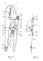
- Figure 3 is a plan view of the pliers in the end position of a pressing process and
- Figure 4 is a schematic representation to illustrate the knee lever effective angle.
Eine in Figur 1 dargestellte Zange 1 ist von an sich bekannter Bauart. Am vorderen Ende eines festen Zangengriffs 2 ist eine Preßbacke 3 fest mit dem Zangengriff 2 verbunden vorgesehen, welche mit einem Preßprofil 4 ausgestattet ist. Am festen Zangengriff 2 ist ebenfalls am vorderen Ende eine bewegliche Preßbacke 5 schwenkbar gelagert, welche ebenfalls mit einem das Preßprofil 4 ergänzenden Preßprofil versehen ist. Zur Lagerung dient dabei ein Bolzen 6.A pliers 1 shown in Figure 1 is of a type known per se. At the front end of a fixed pliers handle 2, a
Zwischen dem festen Zangengriff 2 und der Preßbacke 5 ist ein Kniehebeltrieb angeordnet, der einerseits aus einem Teil eines beweglichen Zangengriffs 7, nämlich einem Kniehebelabschnitt 18, und einem Druckhebel 8 gebildet ist. Der bewegliche Zangengriff 7 ist dabei an der beweglichen Preßbacke 5 über ein Abstützgelenk 19 angelenkt und der Druckhebel 8 stützt sich im hinteren Ende des Zangengriffs 2 über ein Abstützgelenk 20 ab. Zum Kniehebeltrieb gehört schließlich noch ein Kniegelenk 21, durch welches der Kniehebelabschnitt 18 mit dem Druckhebel 8 gelenkig verbunden ist. Es ist ersichtlich, daß die Länge des Druckhebels 8 sehr viel größer ist als die Länge des Kniehebelabschnitts 18, also die Entfernung des Abstützgelenks 19 von dem Kniegelenk 21. Dieses Größenverhältnis liegt mindestens in der Größenordnung 2:1, vorzugsweise noch höher. Der Kniehebeltrieb wird jedoch nur außerhalb seiner Strecklage, also unter Vermeidung einer Lage, bei der das Kniegelenk 21 auf der Verbindungslinie der Abstützpunkte 19 und 20 zu liegen kommt, benutzt. Erst recht wird eine Totpunktsüberschreitung vermieden. Die Benutzung des Kniehebeltriebs nur bis kurz vor die Strecklage hat seinen Sinn darin, daß zwischen dem Zangengriff 2 und der Preßbacke 5 eine Feder 9 angeordnet ist, die somit in der Lage ist, nach Erreichen der Endlage einer Schließbewegung und damit des Kniehebelwirkwinkels die Zange wieder selbsttätig zu öffnen.Between the fixed pliers handle 2 and the
Das Abstützgelenk 19 des Kniehebelabschnitts 18 und gleichzeitig des beweglichen Zangengriffs 7 an der Preßbacke 5 kann einen Exzenterbolzen 16 aufweisen, um die wirksame Entfernung der beiden Abstützgelenke 19 und 20 zueinander zu verändern und damit den Preßdruck bzw. die Preßkraft der Preßbacken 3 und 5 zueinander in der Schließlage einzustellen oder um durch Verschleiß entstandenes Spiel auszugleichen. In ähnlicher Weise, also auch mit einem Exzenter, kann auch oder nur allein das Abstützgelenk 20 verstellbar sein. Es ist aber auch möglich, im Bereich des Abstützgelenks 20 eine Einstellschraube 17 im festen Zangengriff 2 zu lagern, mit deren Hilfe das Abstützgelenk 20 im festen Zangengriff 2 axial verschoben wird. Beide aufgezeigten Verstellmöglichkeiten, die einzeln oder kombiniert angewendet werden können, dienen allein zur Verstellung des Preßdrucks bzw. der Preßkraft in der Endstellung der Schließbewegung.The
Durch die aufgezeigten Übersetzungs- bzw. Längenverhältnisse der verschiedenen Hebelarme zueinander besitzt die Zange eine große Übersetzung, d. h. mit einer vergleichsweise kleinen Handkraft zwischen dem festen Zangengriff 2 und dem beweglichen Zangengriff 7 ist es möglich, eine erheblich verstärkte Preßkraft im Bereich des Preßprofils 4 auszuüben. Zum verläßlichen Erreichen dieser gewünschten bzw. für ein ordnungsgemäßes Verpressen der Kabelschuhe mit den elektrischen Leitern erforderliche Preßkraft ist eine Zwangssperre vorgesehen, die aus zwei miteinander in Eingriff kommenden Teilen besteht, die im Bereich des Kniegelenks 21 dem Druckhebel 8 zugeordnet angeordnet sind. So weist die Zwangssperre eine auf einem Lagerzapfen 10 drehbar gelagerte Klinke 11 auf. Eine Rückführfeder 12 beaufschlagt die Verschwenkbarkeit der Klinke 11 in eine Mittelstellung hinein. Die K1inke 11 besitzt einen Rastfortsatz 13, der mit einem Zahnsegment 14 zusammenarbeitet, welches fest am beweglichen Zangengriff 7 angeordnet ist bzw. aus dem Material dieses beweglichen Zangengriffs 7 herausgearbeitet ist. Das Zahnsegment 14 weist eine Vielzahl von Zähnen 22 auf, die alle auf einem Kreisbogen um das Kniegelenk 21 angeordnet sind. Durch die bogenförmige Länge des Zahnsegments 14 wird der Wirkungsbereich der Zwangssperre festgelegt. Zweckmäßig wird diese bogenförmige Länge so gewählt, daß die Zwangssperre über den wesentlichen Weg des Schließvorgangs in Eingriff ist und nur in der Anfangs- und in der Endstellung der Rastfortsatz 13 außer Eingriff zu den Zähnen 22 kommt. Hierfür ist bezüglich der Endstellung ein Freiraum 23 am beweglichen Zangengriff 7 im Anschluß an das Zahnsegment 14 angeordnet, während auf der anderen Seite - der Anfangsstellung einer Schließbewegung zugeordnet - das Zahnsegment 14 endet, so daß hier auch gleichsam ein Freiraum vorgesehen ist, wie dies insbesondere Figur 2 zeigt.Due to the shown translation or length ratios of the different lever arms to each other, the pliers have a large translation, ie with a comparatively small hand force between the fixed pliers handle 2 and the movable pliers handle 7, it is possible to exert a considerably increased pressing force in the area of the
Im Bereich des Kniegelenks 21 ist ferner eine Einstellschraube 15 gelagert, die den Druckhebel 8 durchsetzt und in einem entsprechenden Gewinde so relativ zum Druckhebel 8 verstellt werden kann, daß ihr aus dem Druckhebel 8 herausreichendes Ende mehr oder weniger weit vorsteht und damit mit dem Rücken des beweglichen Zangengriffs 7, der einen U-förmigen Querschnitt aufweisen kann, zusammenarbeitet. Es werden hier Anschläge 24 und 25 gebildet, wie dies insbesondere aus Figur 1 ersichtlich ist. Diese Anschläge 24 und 25 verhindern die Einnahme einer Streck- oder Totpunktslage des Kniehebeltriebs und begrenzen somit die Verschwenkbarkeit. Es wird der Kniehebelwirkwinkel damit festgelegt. Dies erfolgt in Abstimmung auf die Zwangssperre, d. h. die Anschläge 24 und 25 kommen dann zur Anlage, wenn gerade während eines Schließvorgangs der Rastfortsatz 13 von dem letzten Zahn 22 des Zahnsegments 14 freigekommen ist und in den Freiraum 23 einschwenkt.In the area of the knee joint 21, an adjusting
Die Arbeitsweise der Zange 1 mit der Zwangssperre ist folgende:The operation of the pliers 1 with the forced lock is as follows:
Ausgehend von der Öffnungslage gemäß Figur 2, in welcher die Zwangssperre anfänglich frei ist, werden die zu verpressenden Teile in das Preßprofil 4 eingelegt und der bewegliche Zangengriff 7 wird unter Annäherung auf den festen Zangengriff 2 verschwenkt, so daß der Kniehebeltrieb seine Funktion beginnt und die bewegliche Preßbacke 5 um den Bolzen 6 in Richtung auf die Schließstellung verschwenkt wird. Dabei kommt der Rastfortsatz 13 der Klinke 11 in Wirkverbindung zu den Zähnen 22 des Zahnsegments 14. Sobald der erste Zahn überschritten ist, kann die Schließbewegung in ihrer Richtung nicht mehr verlassen bzw. aufgehoben werden, es sei denn, es läge eine offensichtliche Fehleinlegung der zu verpressenden Teile vor. Zu diesem Zweck ist es möglich, manuell gezielt durch Betätigung eines Auslösers 26 an der Klinke 11 den Rastfortsatz 13 aus einer Lücke zwischen zwei Zähnen 22 auszuheben, so daß die Zwangssperre wirkungslos wird. In der Regel, also bei ordnungsgemäß eingelegten zu verpressenden Teilen wird der Auslöser 26 natürlich nicht betätigt, sondern der Schließvorgang setzt sich fort bis in die Stellung gemäß Figur 1, in welcher die Zwangssperre noch geschlossen ist, jedoch die Preßbacken 3 und 4 bereits nahezu aufeinanderliegen. Um die Endlage eines Verpressungsvorgang gemäß Figur 3 zu erreichen, ist es nun erforderlich, den beweglichen Zangengriff 7 weiter zu drücken und eine noch weitergehendere Annäherung zu dem festen Zangengriff 2 zu erreichen. Dabei wird der erforderliche Endpreßdruck am Preßprofil 4 erreicht und der Rastfortsatz 13 kommt von den Zähnen 22 des Zahnsegments 14 frei und schwenkt in den Freiraum 23 ein. Dabei gelangen die Anschläge 24 und 25 in Anlage aneinander, so daß der insoweit reproduzierbar eingestellte Kniehebelwirkwinkel nicht mehr vergrößert werden kann. Die Verpressung der Teile ist ordnungsgemäß erfolgt und durch Loslassen bzw. Nachgeben an dem beweglichen Zangengriff 7 ist die Feder 9 in der Lage, die Zange selbsttätig zu öffnen, weil eine Totpunktslage vermieden worden ist.Starting from the open position according to FIG. 2, in which the positive lock is initially free, the parts to be pressed are inserted into the pressed
Durch eine Verstellung der Entfernung beider Abstützgelenke 19 und 20 zueinander, also entweder durch Verstellung des Abstützgelenks 19 und/oder des Abstützgelenks 20 kann der in der Endstellung wirksame Preßdruck eingestellt werden, ohne daß dabei der Winkel der Zwangssperre verstellt wird, in welchem diese wirksam wird. Die Verstellung des Preßdrucks ist also unabhängig von der Wirkung der Zwangssperre. Der Winkel, an welcher die Zwangssperre wieder öffnet, bleibt konstant. Um dies zu verdeutlichen, wird auf Figur 4 hingewiesen. Dort sind in schematischer Anordnung das Abstützgelenk 19, das Abstützgelenk 20 und das Kniegelenk 21 dargestellt, wobei ersichtlich ist, daß das Kniegelenk 21 nicht auf einer Verbindungslinie zwischen den Abstützgelenken 19 und 20 liegt, sondern rechts davon. Der Druckhebel 8 und der Kniehebelabschnitt 18 sind durch Striche symbolisiert, so daß zwischen diesen Hebeln 8, 18 der Kniehebelwirkwinkel 27 aufgespannt wird, der, wie ersichtlich, etwas kleiner als 180° ist. Symbolhaft ist das Zahnsegment 14 und die Klinke 11 angedeutet. Das Zahnsegment 14 ist mit dem Kniehebelsabschnitt 18 fest verbunden, während die Klinke 11 auf dem Druckhebel schwenkbar, aber ortsfest gelagert ist. Es ist die Stellung dargestellt, in welcher die Klinke 11 gerade von dem Zahnsegment 14 im Verlauf eines Schließvorgangs freigekommen ist. Hierdurch ist der Kniehebelwirkwinkel 27 festgelegt, der im übrigen durch die Anschläge 24 und 25 gesichert ist, die einen Anschlagswinkel 28 festlegen. Die Summe aus Kniehebelwirkwinkel 27 und Anschlagswinkel 28 beträgt 180°. Man erkennt nun, daß es für die Relativlage der Teile der Zwangssperre, nämlich des Zahnsegments 14 und der Klinke 11 bezüglich des Erreichens der Freigabe nur auf den Kniehebelwirkwinkel 27 ankommt, dagegen nicht auf die Länge des Druckhebels 8 und/oder des Kniehebelabschnitts 18. Eine Verstellung des Abstützgelenks 20, wie dies in Figur 4 in gepunkteter Weise angedeutet ist, also eine Verstellung der wirksamen Länge des Druckhebels 8, führt somit nicht zu einer Veränderung der Eingriffsverhältnisse der Zwangssperre, so daß der Kniehebelwirkwinkel 27 bei einer solchen Preßdruckverstellung konstant bleibt. Gleiches gilt für eine Verstellung des Abstützgelenks 19 oder für eine gleichzeitige Verstellung beider Abstützgelenke 19 und 20.By adjusting the distance between the two
- 1 = Zange1 = pliers
- 2 = fester Zangengriff2 = fixed pliers handle
- 3 = Preßbacke3 = press jaw
- 4 = Preßprofil4 = press profile
- 5 = Preßbacke5 = press jaw
- 6 = Bolzen6 = bolt
- 7 = beweglicher Zangengriff7 = movable pliers handle
- 8 = Druckhebel8 = pressure lever
- 9 = Feder9 = spring
- 10 = Lagerzapfen10 = journal
- 11 = Klinke11 = jack
- 12 = Rückführfeder12 = return spring
- 13 = Rastfortsatz13 = resting process
- 14 = Zahnsegment14 = tooth segment
- 15 = Einstellschraube15 = adjusting screw
- 16 = Exzenterbolzen16 = eccentric bolt
- 17 = Einstellschraube17 = adjusting screw
- 18 = Kniehebelabschnitt18 = toggle section
- 19 = Abstützgelenk19 = support joint
- 20 = Abstützgelenk20 = support joint
- 21 = Kniegelenk21 = knee joint
- 22 = Zähne22 = teeth
- 23 = Freiraum23 = free space
- 24 = Anschlag24 = stop
- 25 = Anschlag25 = stop
- 26 = Auslöser26 = trigger
- 27 = Kniehebelwirkwinkel27 = toggle lever angle
- 28 = Anschlagswinkel28 = stop angle
Claims (6)
Priority Applications (1)
| Application Number | Priority Date | Filing Date | Title |
|---|---|---|---|
| AT87104663T ATE84921T1 (en) | 1986-04-09 | 1987-03-30 | PLIERS FOR PRESSING CABLE LUGS, CABLE CONNECTORS ETC. WITH ELECTRICAL CONDUCTORS, FIBER OPTIC CONDUCTORS ETC. |
Applications Claiming Priority (4)
| Application Number | Priority Date | Filing Date | Title |
|---|---|---|---|
| DE3611861 | 1986-04-09 | ||
| DE3611861 | 1986-04-09 | ||
| DE19873708727 DE3708727A1 (en) | 1986-04-09 | 1987-03-18 | PLIERS FOR CRIMPING CABLE SHOES, CABLE CONNECTORS OD. DGL. WITH ELECTRIC LADDERS, LIGHTWAVE LADES ETC. |
| DE3708727 | 1987-03-18 |
Publications (3)
| Publication Number | Publication Date |
|---|---|
| EP0241798A2 true EP0241798A2 (en) | 1987-10-21 |
| EP0241798A3 EP0241798A3 (en) | 1990-01-10 |
| EP0241798B1 EP0241798B1 (en) | 1993-01-20 |
Family
ID=25842741
Family Applications (1)
| Application Number | Title | Priority Date | Filing Date |
|---|---|---|---|
| EP87104663A Expired - Lifetime EP0241798B1 (en) | 1986-04-09 | 1987-03-30 | Pincers for crimping electrical terminals, cable connectors and the like onto electrical leads, light wave guides, etc |
Country Status (6)
| Country | Link |
|---|---|
| US (1) | US4794780A (en) |
| EP (1) | EP0241798B1 (en) |
| CA (1) | CA1278174C (en) |
| DE (1) | DE3708727A1 (en) |
| ES (1) | ES2038133T3 (en) |
| GR (1) | GR3007183T3 (en) |
Cited By (3)
| Publication number | Priority date | Publication date | Assignee | Title |
|---|---|---|---|---|
| DE19539580A1 (en) * | 1995-10-25 | 1997-04-30 | Rennsteig Werkzeuge Gmbh | Tool for compressing contact elements, such as terminals, on to electrical conductors |
| DE202014100340U1 (en) | 2014-01-27 | 2014-02-19 | Jokari-Krampe Gmbh | Stripping and crimping tool with forced lock |
| US20170113364A1 (en) * | 2015-10-23 | 2017-04-27 | Hong Jin Industry Co., Ltd. | Cutter |
Families Citing this family (41)
| Publication number | Priority date | Publication date | Assignee | Title |
|---|---|---|---|---|
| US5042286A (en) * | 1988-05-09 | 1991-08-27 | C.A. Weidmuller Gmbh & Co. | Manually operated pliers-type tool |
| US5116340A (en) * | 1989-01-26 | 1992-05-26 | Songer Robert J | Surgical securance apparatus |
| US5012666A (en) * | 1989-07-24 | 1991-05-07 | Chen Ching Wen | Crimp tool with adjustable jaw |
| US5105648A (en) * | 1990-02-16 | 1992-04-21 | Rostra Tool Company | Molded lightweight handtool with structural insert |
| DE4129685A1 (en) * | 1991-09-07 | 1993-03-11 | Wolfgang B Thoerner | Manually operated tool for crimping connectors onto wires - has pair of hinged handgrips operating 3-link transmission to apply high force with accurate displacement of tool |
| EP0725708B1 (en) * | 1992-04-06 | 1998-07-08 | Pressmaster Tool Ab | A crimping tool |
| US5280716A (en) * | 1992-11-13 | 1994-01-25 | The Whitaker Corporation | Crimping tool |
| US5596800A (en) * | 1992-12-17 | 1997-01-28 | Cable Ready, Inc. | Crimping tool with ratchet mechanism |
| US5392508A (en) * | 1992-12-17 | 1995-02-28 | Cable Ready, Inc. | Axial deformation crimping tool |
| US5974659A (en) * | 1996-05-23 | 1999-11-02 | Kesinger; Donald A. | Machine for repetitively applying connectors on cable ends to form round connections |
| US6230387B1 (en) * | 1997-10-21 | 2001-05-15 | Panduit Corp. | Optical fiber termination tool |
| US5842371A (en) * | 1998-02-12 | 1998-12-01 | Liaw; Gwo-Jiang | Wire crimper having adjustment mechanism for adjusting pitch of the jaw mouth |
| US5934137A (en) * | 1998-05-08 | 1999-08-10 | Capewell Components Company | Compression assembly tool |
| US6112404A (en) * | 1998-07-07 | 2000-09-05 | Capewell Components Company, Llc | Radial taper tool for compressing electrical connectors |
| US6073472A (en) * | 1999-04-07 | 2000-06-13 | Hollingsworth; Elmont | Measuring terminal crimper |
| US6219905B1 (en) * | 1999-08-30 | 2001-04-24 | Sun Microsystems, Inc. | Heat sink clip tool |
| US6617685B1 (en) | 1999-08-30 | 2003-09-09 | Sun Microsystems, Inc. | Clip heat sink assembly |
| DE10141077B4 (en) * | 2001-08-22 | 2005-02-17 | Daimlerchrysler Ag | Device for connecting two coupling parts |
| US6715333B2 (en) | 2002-03-18 | 2004-04-06 | William Wei Guo Liang | Cutting and crimping device |
| US6711789B2 (en) | 2002-08-14 | 2004-03-30 | Great Neck Saw Manufacturers, Inc. | Clamp |
| US6820326B1 (en) | 2002-10-05 | 2004-11-23 | Capewell Components Company, Llc | Compression assembly tool with multiple split bases |
| DE10346241B3 (en) * | 2003-10-06 | 2004-08-12 | Wezag Gmbh Werkzeugfabrik | Workpiece compression pliers e.g. for compression of pipe or compression fitting, has one hand lever divided into 2 partial levers for 2-stage compression of workpiece |
| US20050214719A1 (en) * | 2004-03-23 | 2005-09-29 | Aesculap Ag & Co. Kg | Method for extracting a tooth |
| US7210327B1 (en) | 2004-12-08 | 2007-05-01 | Capewell Components Company, Llc | Reduced actuation force compression assembly tool |
| US20090199344A1 (en) * | 2007-10-22 | 2009-08-13 | Normark Innovations, Inc. | Fishing tool for crimping ferrules |
| DE102008005472B3 (en) * | 2008-01-22 | 2009-02-26 | Wezag Gmbh Werkzeugfabrik | Pressing tongs for pressing a fitting of tubes and cable shoes comprises a closing mechanism which is actuated depending on hand levers and pressing jaws which move from an opening position into a closed position |
| DE102008012011B3 (en) | 2008-03-01 | 2009-12-03 | Wezag Gmbh Werkzeugfabrik | pliers head |
| DE102009001949B4 (en) | 2009-03-27 | 2011-02-24 | Wezag Gmbh Werkzeugfabrik | Die half and pressing tool |
| EP2305428B1 (en) | 2009-09-30 | 2016-08-31 | Wezag GmbH Werkzeugfabrik | Pliers |
| EP2995424B1 (en) | 2014-09-11 | 2018-12-12 | Wezag GmbH Werkzeugfabrik | Pliers |
| DE202014011110U1 (en) | 2014-09-11 | 2017-11-29 | Wezag Gmbh Werkzeugfabrik | hand tool |
| EP3208044A1 (en) | 2016-02-18 | 2017-08-23 | Wezag GmbH Werkzeugfabrik | Pliers with a knee lever gearbox |
| EP3396796B1 (en) | 2017-04-25 | 2021-07-21 | WEZAG GmbH & Co. KG | Press, crimping or cutting tool and tool group |
| SE540881C2 (en) * | 2017-04-28 | 2018-12-11 | Pressmaster Ab | Hand tool with adjustable release function |
| EP3656504B1 (en) | 2018-11-20 | 2022-02-23 | WEZAG GmbH & Co. KG | Press tool, press tool set, press tool network and method for crimping a workpiece |
| EP3614507B1 (en) | 2018-08-23 | 2021-09-01 | WEZAG GmbH & Co. KG | Pressing or crimping tool |
| EP3763483B1 (en) * | 2019-07-11 | 2022-06-08 | Stanley Black & Decker MEA FZE | Adjustable locking pliers |
| EP3820001B1 (en) | 2019-11-11 | 2022-08-17 | WEZAG GmbH & Co. KG | Crimping pliers and group of crimping pliers |
| CN112792784B (en) * | 2021-01-29 | 2023-07-28 | 神华神东煤炭集团有限责任公司 | Cotter pin assembly device |
| DE102022101938A1 (en) * | 2022-01-27 | 2023-07-27 | Weidmüller Interface GmbH & Co. KG | Manual pressing tool |
| EP4243222A1 (en) | 2022-03-09 | 2023-09-13 | WEZAG GmbH & Co. KG | Crimping tool force sensor and crimping tool |
Citations (3)
| Publication number | Priority date | Publication date | Assignee | Title |
|---|---|---|---|---|
| FR1298930A (en) * | 1960-12-19 | 1962-07-20 | Proner Sa Ets | Pliers especially for crimping |
| DE6605867U (en) * | 1963-07-30 | 1970-07-30 | Siemens Ag | HAND-OPERATED TOOL FOR COMPRESSING ELECTRIC CONNECTING SLEEVES |
| DE2521378A1 (en) * | 1975-05-14 | 1976-11-18 | Reiner Rommel | Tongs for crimping cable connectors - has two movable arms with jaws with die and punch |
Family Cites Families (10)
| Publication number | Priority date | Publication date | Assignee | Title |
|---|---|---|---|---|
| BE527460A (en) * | 1948-01-14 | |||
| BE533170A (en) * | 1953-11-10 | |||
| US3157075A (en) * | 1962-01-17 | 1964-11-17 | Sargent & Co | Plier type tool with motion-compelling mechanism |
| US3611782A (en) * | 1969-04-08 | 1971-10-12 | Thomas & Betts Corp | Compression tool for electrical connectors |
| DE7205611U (en) * | 1972-02-15 | 1972-05-04 | Huber & Suhner Ag | Clamping pliers especially for cable connections |
| GB1522144A (en) * | 1975-10-24 | 1978-08-23 | Holdema Ltd | Crimping and/or cutting device |
| DE2555071C2 (en) * | 1975-12-06 | 1982-04-29 | Pressmaster Ab, Stockholm | Manually operated device for crimping cable lugs, cable connectors or the like. |
| US4080820A (en) * | 1976-09-02 | 1978-03-28 | Walter Kidde & Company, Inc. | In-line crimping tool |
| US4126936A (en) * | 1977-09-29 | 1978-11-28 | Koller Joseph A | Identification system for point to point wiring |
| US4144737A (en) * | 1977-11-01 | 1979-03-20 | Thomas & Betts Corporation | Adjusting mechanism for a tool |
-
1987
- 1987-03-18 DE DE19873708727 patent/DE3708727A1/en active Granted
- 1987-03-30 ES ES198787104663T patent/ES2038133T3/en not_active Expired - Lifetime
- 1987-03-30 EP EP87104663A patent/EP0241798B1/en not_active Expired - Lifetime
- 1987-04-01 US US07/033,509 patent/US4794780A/en not_active Expired - Fee Related
- 1987-04-08 CA CA000534213A patent/CA1278174C/en not_active Expired - Lifetime
-
1993
- 1993-02-26 GR GR930400422T patent/GR3007183T3/el unknown
Patent Citations (3)
| Publication number | Priority date | Publication date | Assignee | Title |
|---|---|---|---|---|
| FR1298930A (en) * | 1960-12-19 | 1962-07-20 | Proner Sa Ets | Pliers especially for crimping |
| DE6605867U (en) * | 1963-07-30 | 1970-07-30 | Siemens Ag | HAND-OPERATED TOOL FOR COMPRESSING ELECTRIC CONNECTING SLEEVES |
| DE2521378A1 (en) * | 1975-05-14 | 1976-11-18 | Reiner Rommel | Tongs for crimping cable connectors - has two movable arms with jaws with die and punch |
Cited By (7)
| Publication number | Priority date | Publication date | Assignee | Title |
|---|---|---|---|---|
| DE19539580A1 (en) * | 1995-10-25 | 1997-04-30 | Rennsteig Werkzeuge Gmbh | Tool for compressing contact elements, such as terminals, on to electrical conductors |
| DE19539580B4 (en) * | 1995-10-25 | 2004-12-02 | Rennsteig Werkzeuge Gmbh | Crimping pliers for pressing contact elements |
| DE202014100340U1 (en) | 2014-01-27 | 2014-02-19 | Jokari-Krampe Gmbh | Stripping and crimping tool with forced lock |
| EP2898990A1 (en) | 2014-01-27 | 2015-07-29 | KRAMPE Immobilien GmbH & Co. KG | Stripping- and crimping tool having ratchet |
| US9570869B2 (en) | 2014-01-27 | 2017-02-14 | Krampe Immobilien Gmbh & Co. Kg | Wire-stripping and crimping pliers with forced lock |
| US20170113364A1 (en) * | 2015-10-23 | 2017-04-27 | Hong Jin Industry Co., Ltd. | Cutter |
| US9789615B2 (en) * | 2015-10-23 | 2017-10-17 | Hong Jin Industry Co., Ltd. | Cutter |
Also Published As
| Publication number | Publication date |
|---|---|
| ES2038133T3 (en) | 1993-07-16 |
| GR3007183T3 (en) | 1993-07-30 |
| DE3708727A1 (en) | 1987-11-12 |
| EP0241798B1 (en) | 1993-01-20 |
| EP0241798A3 (en) | 1990-01-10 |
| DE3708727C2 (en) | 1988-07-28 |
| US4794780A (en) | 1989-01-03 |
| CA1278174C (en) | 1990-12-27 |
Similar Documents
| Publication | Publication Date | Title |
|---|---|---|
| EP0241798B1 (en) | Pincers for crimping electrical terminals, cable connectors and the like onto electrical leads, light wave guides, etc | |
| DE19963097C5 (en) | Pliers for pressing a workpiece | |
| EP0531897B1 (en) | Press tool for crimping a cylindrical pressed article or a pressed article having a cylindrical cross section on a round profile in particular a pipe conduit | |
| EP2107650B1 (en) | Press clamp with a positioning device | |
| DE10346241B3 (en) | Workpiece compression pliers e.g. for compression of pipe or compression fitting, has one hand lever divided into 2 partial levers for 2-stage compression of workpiece | |
| EP0421107B1 (en) | Pliers | |
| DE1615840B2 (en) | CLAMPING PLIERS FOR ELECTRICAL CONNECTORS | |
| EP1110612A2 (en) | Pipetting system with pipette and syringe tip | |
| DE19709639A1 (en) | Crimping pliers for terminal sleeve or cable shoe | |
| DE3719442A1 (en) | Portable press for producing compression joints | |
| DE19834859C2 (en) | Pliers for pressing workpieces | |
| EP0562229A2 (en) | Crimping tool for processing wire terminals | |
| EP1979112B1 (en) | Work transport device | |
| EP1336440B1 (en) | Driver device for workpieces with transfer bars | |
| DE2555071C2 (en) | Manually operated device for crimping cable lugs, cable connectors or the like. | |
| DE10259959B4 (en) | Power chuck and wedge bar for it | |
| EP1496580A1 (en) | Crimping plier | |
| EP0124919A2 (en) | Crimping tongs equipped with a stopper for crimping cable shoes | |
| DE2404161A1 (en) | TOOL, PREFERABLY PLIERS, FOR NOTCHING OR COMPRESSING SLEEVES SUCH AS CABLE LUGS ETC. | |
| DE4424493C2 (en) | Plier-like tool for the positive connection of sheet metal parts | |
| DE2848445C2 (en) | Device for stripping electrical conductors | |
| DE1465916B2 (en) | Notching pliers | |
| DE2313424A1 (en) | DEVICE FOR FORMING A COLLAR ON A WALL, IN PARTICULAR ON A PIPE WALL | |
| DE19955289C2 (en) | Jack puller | |
| EP0278111A1 (en) | Power chuck |
Legal Events
| Date | Code | Title | Description |
|---|---|---|---|
| PUAI | Public reference made under article 153(3) epc to a published international application that has entered the european phase |
Free format text: ORIGINAL CODE: 0009012 |
|
| AK | Designated contracting states |
Kind code of ref document: A2 Designated state(s): AT BE CH ES FR GB GR IT LI LU NL SE |
|
| PUAL | Search report despatched |
Free format text: ORIGINAL CODE: 0009013 |
|
| AK | Designated contracting states |
Kind code of ref document: A3 Designated state(s): AT BE CH ES FR GB GR IT LI LU NL SE |
|
| 17P | Request for examination filed |
Effective date: 19891219 |
|
| 17Q | First examination report despatched |
Effective date: 19920402 |
|
| ITF | It: translation for a ep patent filed |
Owner name: DE DOMINICIS & MAYER S. |
|
| GRAA | (expected) grant |
Free format text: ORIGINAL CODE: 0009210 |
|
| RAP3 | Party data changed (applicant data changed or rights of an application transferred) |
Owner name: WEZAG GMBH WERKZEUGFABRIK |
|
| AK | Designated contracting states |
Kind code of ref document: B1 Designated state(s): AT BE CH ES FR GB GR IT LI LU NL SE |
|
| REF | Corresponds to: |
Ref document number: 84921 Country of ref document: AT Date of ref document: 19930215 Kind code of ref document: T |
|
| GBT | Gb: translation of ep patent filed (gb section 77(6)(a)/1977) |
Effective date: 19930202 |
|
| ET | Fr: translation filed | ||
| REG | Reference to a national code |
Ref country code: GR Ref legal event code: FG4A Free format text: 3007183 |
|
| REG | Reference to a national code |
Ref country code: ES Ref legal event code: FG2A Ref document number: 2038133 Country of ref document: ES Kind code of ref document: T3 |
|
| PLBE | No opposition filed within time limit |
Free format text: ORIGINAL CODE: 0009261 |
|
| STAA | Information on the status of an ep patent application or granted ep patent |
Free format text: STATUS: NO OPPOSITION FILED WITHIN TIME LIMIT |
|
| 26N | No opposition filed | ||
| EPTA | Lu: last paid annual fee | ||
| EAL | Se: european patent in force in sweden |
Ref document number: 87104663.7 |
|
| PGFP | Annual fee paid to national office [announced via postgrant information from national office to epo] |
Ref country code: GB Payment date: 19950313 Year of fee payment: 9 |
|
| PGFP | Annual fee paid to national office [announced via postgrant information from national office to epo] |
Ref country code: AT Payment date: 19950324 Year of fee payment: 9 |
|
| PGFP | Annual fee paid to national office [announced via postgrant information from national office to epo] |
Ref country code: NL Payment date: 19950331 Year of fee payment: 9 Ref country code: GR Payment date: 19950331 Year of fee payment: 9 Ref country code: ES Payment date: 19950331 Year of fee payment: 9 |
|
| PGFP | Annual fee paid to national office [announced via postgrant information from national office to epo] |
Ref country code: LU Payment date: 19950401 Year of fee payment: 9 |
|
| PGFP | Annual fee paid to national office [announced via postgrant information from national office to epo] |
Ref country code: BE Payment date: 19950406 Year of fee payment: 9 |
|
| PGFP | Annual fee paid to national office [announced via postgrant information from national office to epo] |
Ref country code: CH Payment date: 19950418 Year of fee payment: 9 |
|
| PG25 | Lapsed in a contracting state [announced via postgrant information from national office to epo] |
Ref country code: LU Free format text: LAPSE BECAUSE OF NON-PAYMENT OF DUE FEES Effective date: 19960330 Ref country code: GB Effective date: 19960330 Ref country code: AT Effective date: 19960330 |
|
| PG25 | Lapsed in a contracting state [announced via postgrant information from national office to epo] |
Ref country code: LI Effective date: 19960331 Ref country code: CH Effective date: 19960331 Ref country code: BE Effective date: 19960331 |
|
| PG25 | Lapsed in a contracting state [announced via postgrant information from national office to epo] |
Ref country code: ES Free format text: LAPSE BECAUSE OF NON-PAYMENT OF DUE FEES Effective date: 19960401 |
|
| BERE | Be: lapsed |
Owner name: WEZAG G.M.B.H. WERKZEUGFABRIK Effective date: 19960331 |
|
| PG25 | Lapsed in a contracting state [announced via postgrant information from national office to epo] |
Ref country code: GR Free format text: THE PATENT HAS BEEN ANNULLED BY A DECISION OF A NATIONAL AUTHORITY Effective date: 19960930 |
|
| PG25 | Lapsed in a contracting state [announced via postgrant information from national office to epo] |
Ref country code: NL Effective date: 19961001 |
|
| REG | Reference to a national code |
Ref country code: GR Ref legal event code: MM2A Free format text: 3007183 |
|
| REG | Reference to a national code |
Ref country code: CH Ref legal event code: PL |
|
| GBPC | Gb: european patent ceased through non-payment of renewal fee |
Effective date: 19960330 |
|
| NLV4 | Nl: lapsed or anulled due to non-payment of the annual fee |
Effective date: 19961001 |
|
| REG | Reference to a national code |
Ref country code: ES Ref legal event code: FD2A Effective date: 19990201 |
|
| PGFP | Annual fee paid to national office [announced via postgrant information from national office to epo] |
Ref country code: FR Payment date: 19990318 Year of fee payment: 13 |
|
| PGFP | Annual fee paid to national office [announced via postgrant information from national office to epo] |
Ref country code: SE Payment date: 19990322 Year of fee payment: 13 |
|
| PG25 | Lapsed in a contracting state [announced via postgrant information from national office to epo] |
Ref country code: SE Free format text: LAPSE BECAUSE OF NON-PAYMENT OF DUE FEES Effective date: 20000331 |
|
| EUG | Se: european patent has lapsed |
Ref document number: 87104663.7 |
|
| PG25 | Lapsed in a contracting state [announced via postgrant information from national office to epo] |
Ref country code: FR Free format text: LAPSE BECAUSE OF NON-PAYMENT OF DUE FEES Effective date: 20001130 |
|
| REG | Reference to a national code |
Ref country code: FR Ref legal event code: ST |
|
| PG25 | Lapsed in a contracting state [announced via postgrant information from national office to epo] |
Ref country code: IT Free format text: LAPSE BECAUSE OF NON-PAYMENT OF DUE FEES;WARNING: LAPSES OF ITALIAN PATENTS WITH EFFECTIVE DATE BEFORE 2007 MAY HAVE OCCURRED AT ANY TIME BEFORE 2007. THE CORRECT EFFECTIVE DATE MAY BE DIFFERENT FROM THE ONE RECORDED. Effective date: 20050330 |