EP0278111A1 - Power chuck - Google Patents
Power chuck Download PDFInfo
- Publication number
- EP0278111A1 EP0278111A1 EP87119164A EP87119164A EP0278111A1 EP 0278111 A1 EP0278111 A1 EP 0278111A1 EP 87119164 A EP87119164 A EP 87119164A EP 87119164 A EP87119164 A EP 87119164A EP 0278111 A1 EP0278111 A1 EP 0278111A1
- Authority
- EP
- European Patent Office
- Prior art keywords
- control
- rod
- control rod
- jaw
- base jaw
- Prior art date
- Legal status (The legal status is an assumption and is not a legal conclusion. Google has not performed a legal analysis and makes no representation as to the accuracy of the status listed.)
- Granted
Links
Images


Classifications
-
- B—PERFORMING OPERATIONS; TRANSPORTING
- B23—MACHINE TOOLS; METAL-WORKING NOT OTHERWISE PROVIDED FOR
- B23B—TURNING; BORING
- B23B31/00—Chucks; Expansion mandrels; Adaptations thereof for remote control
- B23B31/02—Chucks
- B23B31/10—Chucks characterised by the retaining or gripping devices or their immediate operating means
- B23B31/12—Chucks with simultaneously-acting jaws, whether or not also individually adjustable
- B23B31/16—Chucks with simultaneously-acting jaws, whether or not also individually adjustable moving radially
- B23B31/16233—Jaws movement actuated by oblique surfaces of a coaxial control rod
- B23B31/16237—Details of the jaws
-
- Y—GENERAL TAGGING OF NEW TECHNOLOGICAL DEVELOPMENTS; GENERAL TAGGING OF CROSS-SECTIONAL TECHNOLOGIES SPANNING OVER SEVERAL SECTIONS OF THE IPC; TECHNICAL SUBJECTS COVERED BY FORMER USPC CROSS-REFERENCE ART COLLECTIONS [XRACs] AND DIGESTS
- Y10—TECHNICAL SUBJECTS COVERED BY FORMER USPC
- Y10T—TECHNICAL SUBJECTS COVERED BY FORMER US CLASSIFICATION
- Y10T279/00—Chucks or sockets
- Y10T279/19—Radially reciprocating jaws
- Y10T279/1986—Jaws
Definitions
- the invention relates to a power-operated chuck with radially adjustable clamping jaws, each of which consists of a base jaw guided in a chuck body, which can be actuated by the drive member and an interchangeably connected top jaw, and has at least one connecting pin with a pin axis parallel to the chuck axis, which rotates around the pin axis is mounted in the base jaw and, depending on the rotational position, closes or opens the jaw connection between the base jaw and the top jaw, and at least one control rod guided longitudinally displaceably in the base jaw transversely to the pin axis and between the control rod and the connecting pin a coupling gear is provided that translates displacements of the control rod relative to the base jaw into rotations of the connecting pin and vice versa.
- Chuck of this type are known from DE-PS 35 10 457 and allow an automatic change of the top jaws with the help of a jaw carrier, the when delivering to the chuck, actuating the control rods releases the jaw connection, exchanges the top jaws for new top jaws and closes the jaw connection again by actuating the control rods.
- the connecting pins are each guided in a nut thread of the base jaw and have at the other end a locking head which is narrower in a direction transverse to the axis of the pin, wider in the vertical direction and protrudes beyond the locking shaft and which engages in a locking receptacle in the top jaw, whereby the bolt head can be inserted axially into the bolt receptacle in the rotational position of the connecting pin corresponding to the unlocked state and, in the rotational position corresponding to the locked state, with its bolt shoulders in the bolt receptacle axially positively engages undercuts.
- the connecting pin has on its part located in the base jaw a toothing in the manner of a toothed pinion and the control rod has a cross toothing which meshes with the toothing of the connecting pin in the manner of a toothed rack.
- the control rods are guided in the tangential direction, i.e. transversely to the chuck axis and to the direction of adjustment of the respective base jaw, and can be adjusted by means of plungers which are axially guided in the chuck body and can be actuated from outside the chuck body by the jaw support against the force of return springs and are located via wedge gears with the tappets in Intervention.
- Axial on pressing the plunger into the chuck body against the force of the return springs therefore leads to displacement of the control rods and, via the associated rotation of the connecting pins, to locking or unlocking the top jaws.
- the connecting pin is rotated in its direction of rotation corresponding to the locking, the locking shoulders of the locking head lie behind the undercuts in the locking receptacle and at the same time the top jaw braces against the base jaw due to the axial tightening of the connecting pin in its mother thread.
- the invention has for its object to provide a chuck of the type mentioned in such a way that actuating and force members for the adjustment of the control rods are unnecessary on the jaw carrier.
- This object is achieved according to the invention in that the guidance of the control rod in the base jaw runs parallel to the guidance of the base jaw in the chuck body, that a control member is provided for the control rod through which the control rod can be determined against displacements with respect to the chuck body, and that the base jaw is displaceable by its drive member, even when the control rod is locked, for rotating the connecting pin.
- the clamping drive for the clamping jaws serves not only for clamping the workpiece, but also at least for the final tightening or initial loosening of the locking state of the jaw connection.
- the force compensation element is expediently designed as a lever with the same arm, which is articulated at the ends of its lever arms with the two control rods and is rotatably connected about the middle of the lever to an adjusting rod guided in the base jaw parallel to the control rods, on which the control element engages. If, in particular, the two control rods are always only subjected to pressure in a manner to be described later, the force compensation element is preferably supported on the one hand with pressure lugs on the end against one of the two control rods and on the other hand against the actuating rod via a cylinder surface which enables its rotation.
- the gears coupling the control rods to the connecting pins are each in the form of a pinion on the connecting pin and a toothed strip engaging therein on the control rod trained, it is recommended that the two control rods in the direction of the pin axes are guided directly to each other and each have a longitudinal recess, which receives the pinion on each control rod that is not in engagement with it via the adjustment path of the control rod.
- the result is a very compact, space-saving and particularly force-resistant arrangement of the two control rods with their force compensation element.
- control member is a bolt which is guided in the chuck body and which is in the locking position with a bolt head engages positively and non-positively in bolt receptacles of the control rod or actuating rod transverse to their guide direction. Then the base jaw can first be moved in one direction with respect to the determined control or actuating rod and then together with the control or actuating rod released again by the bolt, which in the latter direction with the number of repetitions is repeated in the latter direction increasing displacement of the control or actuating rod relative to the base jaw results.
- a particularly preferred embodiment for this in terms of design is characterized in that the control rod or actuating rod is guided in a groove of the base jaw which is open towards the chuck body and is provided on the open groove side with a toothed strip which forms the bolt receptacles, and that the bolt is in its longitudinal direction is a power-actuated bolt that can be moved back and forth and has on its forehead facing the control rod or actuating rod a locking toothing that fits into the toothed strip as a locking head.
- control element is designed as a force-actuated actuator which is guided in the chuck body transversely to the guide direction of the control rod or control rod and has a control curve which extends along its travel path and which has a stop for the control rod or Control rod forms and by means of which the control rod or control rod is displaceable in relation to the base jaw held by its drive member during the adjustment of the control member.
- control member is an annular disc which is rotatably mounted in a concentric annular groove of the chuck body about the chuck axis, that the annular groove is open to the base jaws, that on each base jaw the control rod or control rod in one is guided to the annular groove open groove, and that the annular disc on its side facing the base jaws has the control cam which bears the control rod or actuating rod with a stop member. Rotation of the control element then results in displacements of the control or adjusting rod corresponding to the course of the control curve.
- Embodiment which is characterized in that the control member forms a free passage for the stop member in a predetermined rotational position in the guide direction of the control rod or actuating rod, which connects the control cam with one cam branch each to this free passage in both directions of rotation of the control member which one controls the locking movement, the other the unlocking movement of the control rod or control rod, and that each of these two cam branches has a stop surface on which the control rod or control rod is held in the direction of the locking movement or unlocking movement of the base jaw.
- the base jaws for workpiece clamping can be adjusted unaffected by the control member or its control cams.
- control or actuating rod can be displaced with little force in the locking or unlocking direction via the control cam or held on the stop surface formed by the respective curve branch in order to actuate the base jaw in to firmly tighten the jaw connection in one direction or the other, or to loosen the tightened jaw connection.
- the arrangement is such that the control element is a control piston which is guided axially and concentrically in the chuck body, so that for each base jaw two opposite ones on the connecting pin, Control rods or control rods moving in opposite directions are provided, and that the control member has a separate control curve for each of the two control rods or control rods, which one of the two control rods or control rods only has during the locking process, the other only during the unlocking process, each with its radial inner rod end abuts.
- control rods or actuating rods are always only subjected to pressure when the control member drives, and the locking and unlocking movement of the base jaw is always radially inward, and that of the control or actuating rods is directed radially outwards.
- control member is arranged in the chuck body with a radial displacement play for force compensation between the control rods or adjusting rods of all base jaws and is only moved in its axial position corresponding to the completely open jaw connection into a center hole in the chuck body which eliminates radial play .
- the purpose of switching off the radial play of the control member in its axial position corresponding to the completely open jaw connection is to ensure that on each of the base jaws the connecting pins are actually exactly in the rotational position allowing the axial removal or placement of the top jaws.
- the stop surface on the control curve for the locking process on the control curve for the unlocking process has a recess for free entry of the associated one Control or actuating rod end corresponds and that the stop surface of the control cam adjoining this recess is radially higher by at least the stroke that the base jaw must carry out to open the jaw connection. Then the stop or control rod respectively holding surfaces of both control cams are close together in the axial displacement direction of the control member, so that its displacement path is small if, starting from the locked state, the control or actuating rod causing the unlocking on the stop surface assigned to it Finding to be brought.
- control cams can have sections formed as flat wedge surfaces inclined against the chuck axis, which the control or. Place the rod ends with correspondingly inclined sloping surfaces. In this way, wedge gears are created between the control member and the control or actuating rods, which enable optimum force and displacement ratios.
- the power-operated chuck shown in FIGS. 1 and 2 has three radially adjustable clamping jaws, each of which consists of a drivable base jaw 2 guided in a chuck body 1 and one arranged on the end face of the base jaw 2, in the drawing for simplicity because of the top jaw, not shown.
- the base jaws 2 are driven by means of a drive member 4, which is axially adjustable in the chuck body 1, via a wedge hook connection 5 of a conventional type.
- any other actuator for the base jaws 2 is of course also possible within the scope of the invention.
- the top jaws are, as described in detail in essentially the same way in DE-PS 35 10 457, exchangeably attached to the base jaws 2, the base jaws 2 and the top jaws each in a toothing 6 with toothed strips extending transversely to the guide direction of the base jaws 2 are in mutual engagement.
- the connection between the top jaw and the base jaw 2 is made by two connecting pins 7 with a pin axis 9 parallel to the chuck axis 8. These connecting pins 7 are arranged next to one another at a distance in the direction of adjustment of the base jaw 2.
- Each connecting pin 7 is with its lining-side, thread-bearing pin end in a nut thread 11 of the base jaw 2.
- the connecting pin 7 carries a locking head 12 which has different dimensions in two directions perpendicular to one another and to the pin axis 9, that is to say narrower in one direction and wider in the other and in this direction forms locking shoulders 3 projecting outward beyond the pin shaft.
- This locking head 12 engages in a locking receptacle provided in the top jaw, the locking head being axially insertable into the locking receptacle in the rotational position of the connecting pin 7 corresponding to the unlocking state and with its locking shoulders 3 one in the locking receptacle in the rotational position corresponding to the locked state provided undercut axially positively behind.
- 1 and 2 show the connecting pin 7 in their respective rotational position corresponding to the locking state.
- each connecting pin 7 has a toothing 20 in the manner of a toothed pinion on its part located in the base jaw 2.
- control rods 10, 10 ⁇ Transverse to the pin axis 9 longitudinally displaceable in the base jaw 2 control rods 10, 10 ⁇ have a meshing with the teeth 20 of the connecting pin 7 cross teeth 21 in the manner of a toothed strip, so that the displacement of the control rods 10, 10 ⁇ in their longitudinal direction leads to corresponding rotary movements of the connecting pin 7 .
- the guidance of the control rods 10, 10 ⁇ runs in the base jaw 2 parallel to the guidance of the base jaw 2 in the chuck body 1.
- a control member 13 is provided for the control rods 10, 10 ⁇ , by means of which the control rods 10, 10 ⁇ are established against displacements with respect to the chuck body 1 can be.
- the base jaws 2 are displaceable by their drive member 4, even when the control rods 10, 10 ⁇ are found, for rotating the connecting pins 7.
- the clamping stroke of the base jaws 2 can be used to forcefully completely screw the connecting pins 7 into the locking position, or to loosen them, in the case of respectively determined control rods 10, 10 ⁇ by the resulting relative displacement between the control rods 10, 10 ⁇ and the base jaw 2 unscrew the jaw connection from the locked position.
- control member 13 is a in the chuck body 1 transversely to the guide direction of the control rods 10, 10 ⁇ guided, power-operated movable actuator which has at least one control curve 14 extending along its travel path, which forms a stop for the control rods 10, 10 ⁇ and by means of which the control rods 10, 10 ⁇ are displaceable in relation to the base jaw 2 held by their drive member 4 during the adjustment of the control member 13.
- the control member 13 is a control piston which is guided axially and concentrically in the chuck body 1 and can be adjusted via an adjusting tube 35.
- the control member 13 has its own control cam 14, 14 ⁇ for each of the two control rods 10, 10 ⁇ . These control cams 14, 14 ⁇ is the one control rod 10 ⁇ only during the locking process, the other control rod 10 only during the unlocking process with its radially inner rod end.
- the radial stroke indicated by the double arrow 15, which the base jaws 2 have to carry out for powerfully closing or opening the jaw connection, is therefore somewhat larger than the maximum allowable clamping stroke of the base jaws 2.
- the control member 13 is in the chuck body 1 with a radial displacement play 17 for force compensation between the Control rods 10, 10 ⁇ of all base jaws 2 are arranged and only in their axial position corresponding to the completely open jaw connection, that is to say completely retracted in FIG. 1, are moved into a centering bore 19 in the chuck body 1 that eliminates the radial play.
- This centering of the control member 13 has the effect that the control rods 10 causing the unlocking are all in a corresponding radial position via the stop surfaces 14.4 assigned to them, and thus all the connecting pins 7 are completely rotated into their rotational position corresponding to the unlocking, so that the pin head 12 emerges from the top jaws can, the top jaws axially removed from the connecting pin 7, or they can be attached.
- the stop surface 14.1 ⁇ on the control cam 14 ⁇ for the locking process corresponds to a recess 14.2 on the control cam 14 for the unlocking process Free entry of the end of the control rod 10 assigned to it.
- the stop surface 14.1 of the control cam 14 adjoining this recess 14.2 is radially higher by at least the stroke corresponding to the double arrow 15, which the base jaw 2 must carry out to open the jaw connection.
- the control cams 14, 14 ⁇ also have sections 14.3, 14.3 ⁇ , which are designed as flat wedge surfaces inclined against the chuck axis 8. These sections are the control rods 10, 10 ⁇ with correspondingly inclined inclined surfaces 18, 18 ⁇ .
- the control rod 10 ⁇ causes the locking
- the control rod 10 the unlocking
- the state shown in Fig. 3.1 corresponds to the unlocked position of the connecting pin 7.
- the locking rod 10 ⁇ is shifted radially inward and lies against the cam 14 ⁇ . If the control member 13 is now moved axially forward in the direction of arrow 13.1, the control rod 10 ⁇ is pushed radially outward until its rod end runs onto the stop surface 14.1 ⁇ , as shown in FIG. 3.2. 3.3, the base jaw 2 is now adjusted radially inwards, as indicated by the arrow 2.2.
- the control rod 10 serving for unlocking has entered the recess 14.2, as is indicated by dash-dotted lines in FIG. 3.3.
- the base jaw 2 is first moved radially outward to the largest setting radius 16 in accordance with the arrow 2.3 and then the control member 13 is withdrawn axially in accordance with the arrow 13.2 to such an extent that the end of the control rod 10 is above the stop surface 14.1. This state is shown in Fig. 3.4.
- the base jaw 2 is turned radially inwards in the direction of the arrow 2.4 in accordance with FIG. 3.5 moves, wherein the control rod 10 held on the stop surface 14.2 stops.
- FIGS. 4 to 6 differs from the chuck just described ter only in that each of the control rods 10, 10 ⁇ twice, namely a separate control rod pair is provided for each connecting pin 7. These two control rods 10.1, 10.2, or 10.1 ⁇ , 10.2 ⁇ are coupled to each other in the direction of displacement by a force compensation element 23 and cannot be determined directly, but rather via the force compensation element 23 by the control element 13 common to the two control rods.
- the force compensating member 23 is designed as a lifting arm with the same arm, which is articulated with the ends of its lever arms to the two control rods 10.1, 10.2 or 10.1 ⁇ , 10.2 ⁇ and rotatable about the middle of the lever to an adjusting rod 24 guided in the base jaw 2 parallel to the control rods is connected to which the control member 13 engages. Since the control rods are only subjected to pressure, the force compensating member 23 is supported on the one hand with pressure lugs 23.1 at the end against one of the two control rods 10.1, 10.2 or 10.1 ⁇ , 10.2 ⁇ and on the other hand against the actuating rod 24 by means of a cylinder surface 23.2 which enables its rotation.
- the two control rods 10.1, 10.2 and 10.1 ⁇ , 10.2 ⁇ are guided directly to one another in the direction of the pin axis 9 and each provided with a longitudinal recess 25 which accommodates the pinion 20 on each control rod that is not in engagement with it via the adjustment path of the control rod . This ensures that the the two connecting pins 7 of each base jaw 2 can be adjusted with the same force and completely into their respective rotational position corresponding to the locking or unlocking state.
- the control member 13 is an annular disc which is rotatably mounted in a concentric annular groove 26 of the chuck body 1 about the chuck axis 8.
- the rotary drive takes place via an adjusting tube 27 by a hydraulic or pneumatic rotary piston, not shown.
- the annular groove 26 is open to the base jaws 2.
- the control rod 10 is guided in a groove 28 which is open towards the annular groove 26.
- the annular disc On its side facing the base jaws 2, the annular disc has the control cam 14, against which the control rod 10 rests with a stop member 29. In the rotational position shown in FIG.
- the control member 13 forms a free passage for the stop member 19 running in the guide direction of the control rod 10. In this rotational position, the clamping movement of the base jaw 2 is therefore not impeded by the control member 13. In both directions of rotation, the control member 13 connects the control cam 14 to this free passage, each with a cam arm, of which the cam arm 14a controls the locking movement, the other cam arm 14b controls the unlocking movement of the control rod.
- Each of these two cam branches 14a, 14b forms a stop 30a, 30b, on which the control rod 10 is held in the direction of the locking movement or unlocking movement of the base jaw 2.
- this chuck can be described as follows: To lock the base jaw 2 moves inwards, the stop member 29 of the control rod 10 moves from position 29.1 to position 29.2. Next, the control member 13 is rotated to the right by the angle ⁇ , as a result of which the stop member 29 is displaced from the position 29.2 to the position 29.4 via the control cam 14a. Now the base jaw 2 moves outwards, the stop member 29 and thus the control rod 10 being held on the stop 30a, so that the connecting pins 7 are rotated into the locking position with the high clamping force of the base jaw 2. The jaw connection is now closed. If the control member 13 now rotates by the angle ⁇ to the left into the starting position, the free clamping movements of the base jaws 2 are possible again.
- the base jaw 2 first moves outwards, as a result of which the stop member 29 and accordingly the control rod 10 move into position 29.3.
- the control member 13 now rotates by the angle ⁇ to the left so that the stop 30b comes under the stop member 29.
- the base jaw 2 then moves inwards, the stop member 29 and thus the control rod 10 at the stop 30b are held so that the connecting pins 7 release from their locking position under the high clamping force of the base jaws 2.
- the control member 13 now rotates further by the angle ⁇ to the left, as a result of which the stop member 29 and thus the control rod 10 move from the position 29.3 to the position 29.1 via the control cam 14b.
- the connecting pins 7 pivot into their rotational position corresponding to the complete unlocking and release the top jaw.
- the control member 13 can then be turned back to the right into the starting position by the angles ⁇ and ⁇ .
- the control member 13 is a bolt guided in the chuck body 1, which in the locking position shown in the figure engages positively and non-positively in the bolt receptacles 31 of the control rod 10 transversely to the guide direction thereof with a bolt head 30.
- the control rod 10 is guided in a groove 32 of the base jaw 2 which is open towards the chuck body 1 and is provided on the open groove side with a toothed strip which forms the locking receptacles 31.
- the bolt is a cylindrical bolt which can be moved back and forth in its longitudinal direction by means of a hydraulically or pneumatically actuated piston 33 and which is counteracted by lateral guide projections which run in corresponding grooves 34 in the chuck body 1 Rotation about its axis 35 is secured so that the transverse toothing on its forehead facing the control rod 10, which acts as a locking head 30 and which fits into the toothed strip, is always aligned with the tooth profile on the toothed strip.
- the base jaw 2 moves to the outermost position for locking.
- the control member 13 is moved by the power piston 33 into the engagement position on the control rod 10 shown in the drawing.
- the base jaw 2 then moves radially inward by the greatest possible clamping stroke, the control rod 10 being held by the control member 13, so that there is a relative displacement between the control rod 10 and the base jaw 2, which rotates the connecting pin 7 in the direction of rotation corresponding to the locking movement .
- the control member 13, actuated by the piston 33 moves back out of engagement and releases the control rod 10.
- the base jaw 2 moves back into its outer position and takes the control rod 10 with it, so that the connecting pins 7 do not turn back.
Abstract
Die durch ein Antriebsglied radial verstellbaren Spannbacken besitzen jede eine im Futterkörper (1) geführte Grundbacke (2) und eine damit auswechselbar verbundene Aufsatzbacke, sowie mindestens einen Verbindungszapfen (7) der drehbar um die Zapfenachse in der Grundbacke (2) gelagert ist und je nach Drehlage die Backenverbindung zwischen der Grundbacke und der Aufsatzbacke schließt oder öffnet. Mindestens eine längsverschieblich in der Grundbacke (2) geführte Steuerstange (10, 10') ist mit dem Verbindungszapfen (7) durch ein Getriebe (20, 21) derart gekoppelt, daß Verschiebungen der Steuerstange (10, 10') relativ zur Grundbacke (2) in Verdrehungen des Verbindungszapfens (7) und umgekehrt umgesetzt werden. Die Führung der Steuerstange (10, 10') in der Grundbacke (2) verläuft parallel zur Führung der Grundbacke (2) im Futterkörper (1). Für die Steuerstange (10, 10') ist ein Steuerglied (13) vorgesehen, durch das die Steuerstange (10, 10') gegen Verschiebungen in Bezug auf den Futterkörper (1) feststellbar ist. Die Grundbacke (2) ist durch ihr Antriebsglied (5) auch bei festgestellter Steuerstange (10, 10') zum Verdrehen des Verbindungszapfens (7) verschiebbar. Daher kann bei festgestellter Steuerstange der Verbindungszapfen (7) auch durch Verstellen der Grundbacke (2) kraftstark gedreht werden.The clamping jaws, which can be adjusted radially by a drive member, each have a base jaw (2) guided in the chuck body (1) and an interchangeably connected top jaw, as well as at least one connecting pin (7) which is rotatably mounted about the pin axis in the base jaw (2) and depending on Rotation position closes or opens the jaw connection between the base jaw and the top jaw. At least one control rod (10, 10 ') which is displaceable longitudinally in the base jaw (2) is coupled to the connecting pin (7) by a gear (20, 21) in such a way that displacements of the control rod (10, 10') relative to the base jaw (2 ) in rotations of the connecting pin (7) and vice versa. The control rod (10, 10 ') is guided in the base jaw (2) parallel to the guide of the base jaw (2) in the chuck body (1). A control element (13) is provided for the control rod (10, 10 '), by means of which the control rod (10, 10') can be locked against displacement in relation to the chuck body (1). The base jaw (2) can be displaced by its drive member (5) even when the control rod (10, 10 ') is locked in order to turn the connecting pin (7). Therefore, when the control rod is locked, the connecting pin (7) can also be rotated powerfully by adjusting the base jaw (2).
Description
Die Erfindung betrifft ein kraftbetätigtes Spannfutter mit durch ein Antriebsglied radial verstellbaren Spannbacken, deren jede aus einer in einem Futterkörper geführten, vom Antriebsglied betätigbaren Grundbacke und einer mit der Grundbacke auswechselbar verbundenen Aufsatzbacke besteht und mindestens einen Verbindungszapfen mit zur Futterachse paralleler Zapfenachse aufweist, der drehbar um die Zapfenachse in der Grundbacke gelagert ist und je nach Drehlage die Backenverbindung zwischen der Grundbacke und der Aufsatzbacke schließt oder öffnet, und wobei mindestens eine quer zur Zapfenachse längsverschieblich in der Grundbacke geführte Steuerstange und zwischen der Steuerstange und dem Verbindungszapfen ein sie miteinander koppelndes Getriebe vorgesehen ist, das Verschiebungen der Steuerstange relativ zur Grundbacke in Verdrehungen des Verbindungszapfens und umgekehrt umsetzt.The invention relates to a power-operated chuck with radially adjustable clamping jaws, each of which consists of a base jaw guided in a chuck body, which can be actuated by the drive member and an interchangeably connected top jaw, and has at least one connecting pin with a pin axis parallel to the chuck axis, which rotates around the pin axis is mounted in the base jaw and, depending on the rotational position, closes or opens the jaw connection between the base jaw and the top jaw, and at least one control rod guided longitudinally displaceably in the base jaw transversely to the pin axis and between the control rod and the connecting pin a coupling gear is provided that translates displacements of the control rod relative to the base jaw into rotations of the connecting pin and vice versa.
Spannfutter dieser Art sind aus der DE-PS 35 10 457 bekannt und ermöglichen einen automatischen Wechsel der Aufsatzbacken mit Hilfe eines Backenträgers, der beim Zustellen an das Spannfutter durch Betätigen der Steuerstangen die Backenverbindung löst, die Aufsatzbacken gegen neue Aufsatzbacken auswechselt und durch erneutes Betätigen der Steuerstangen die Backenverbindung wieder schließt. Die Verbindungszapfen sind jeweils in einem Muttergewinde der Grundbacke geführt und besitzen am anderen Ende einen in einer Richtung quer zur Zapfenachse schmaleren, in der dazu senkrechten Richtung breiteren und über den Zapfenschaft auswärts vorstehende Riegelschultern bildenden Riegelkopf, der in eine Riegelaufnahme in der Aufsatzbacke greift, wobei der Riegelkopf in der dem Entriegelungszustand entsprechenden Drehlage des Verbindungszapfens axial in die Riegelaufnahme einsteckbar ist und in der dem Verriegelungszustand entsprechenden Drehlage mit seinen Riegelschultern in der Riegelaufnahme vorgesehene Hinterschneidungen axial formschlüssig hinterfaßt. Weiter besitzt der Verbindungszapfen an seinem in der Grundbacke befindlichen Teil eine Verzahnung nach Art eines Zahnritzels und die Steuerstange eine mit der Verzahnung des Verbindungszapfens kämmende Querverzahnung nach Art einer Zahnstange. Die Steuerstangen sind in tangentialer Richtung, also quer zur Futterachse und zur Verstellrichtung der jeweiligen Grundbacke, geführt und mittels im Futterkörper axial geführter und von außerhalb des Futterkörpers durch den Backenträger gegen die Kraft von Rückstellfedern betätigbarer Stößel verstellbar und stehen dazu über Keilgetriebe mit den Stößeln im Eingriff. Axiales Ein drücken der Stößel in den Futterkörper gegen die Kraft der Rückstellfedern führt daher zur Verschiebung der Steuerstangen und über die damit verbundene Verdrehung der Verbindungszapfen zu einem Ver- oder Entriegeln der Aufsatzbacken. Bei der Verdrehung des Verbindungszapfens in seiner dem Verriegeln entsprechenden Drehrichtung legen sich die Riegelschultern des Riegelkopfes hinter die Hinterschneidungen in der Riegelaufnahme und gleichzeitig verspannt sich die Aufsatzbacke gegen die Grundbacke wegen des axialen Anzuges des Verbindungszapfens in seinem Muttergewinde. Das Verdrehen der Verbindungszapfen erfordert daher umso höhere Kraft, je fester die Verbindungszapfen in ihrem Muttergewinde bereits angezogen sind, so daß im Ergebnis für die jeweils letzte Phase des Verriegelungsvorgangs bzw. für die erste Phase des Entriegelungsvorgangs besonders hoher Kraftaufwand benötigt wird, wenn die Backenverbindung in verriegelten Zustand ausreichend formstabil und kraftsteif sein soll. Diesen hohen Kraftaufwand mit Hilfe des Backenträgers zu erbringen, ist in der Praxis aufwendig und umständlich.Chuck of this type are known from DE-PS 35 10 457 and allow an automatic change of the top jaws with the help of a jaw carrier, the when delivering to the chuck, actuating the control rods releases the jaw connection, exchanges the top jaws for new top jaws and closes the jaw connection again by actuating the control rods. The connecting pins are each guided in a nut thread of the base jaw and have at the other end a locking head which is narrower in a direction transverse to the axis of the pin, wider in the vertical direction and protrudes beyond the locking shaft and which engages in a locking receptacle in the top jaw, whereby the bolt head can be inserted axially into the bolt receptacle in the rotational position of the connecting pin corresponding to the unlocked state and, in the rotational position corresponding to the locked state, with its bolt shoulders in the bolt receptacle axially positively engages undercuts. Furthermore, the connecting pin has on its part located in the base jaw a toothing in the manner of a toothed pinion and the control rod has a cross toothing which meshes with the toothing of the connecting pin in the manner of a toothed rack. The control rods are guided in the tangential direction, i.e. transversely to the chuck axis and to the direction of adjustment of the respective base jaw, and can be adjusted by means of plungers which are axially guided in the chuck body and can be actuated from outside the chuck body by the jaw support against the force of return springs and are located via wedge gears with the tappets in Intervention. Axial on pressing the plunger into the chuck body against the force of the return springs therefore leads to displacement of the control rods and, via the associated rotation of the connecting pins, to locking or unlocking the top jaws. When the connecting pin is rotated in its direction of rotation corresponding to the locking, the locking shoulders of the locking head lie behind the undercuts in the locking receptacle and at the same time the top jaw braces against the base jaw due to the axial tightening of the connecting pin in its mother thread. The twisting of the connecting pins therefore requires the higher the force, the more firmly the connecting pins are already tightened in their mother thread, so that, as a result, particularly great effort is required for the last phase of the locking process or for the first phase of the unlocking process when the jaw connection is in locked state should be sufficiently stable and rigid. In practice, this high expenditure of force with the aid of the jaw carrier is complex and cumbersome.
Der Erfindung liegt die Aufgabe zugrunde, ein Spannfutter der eingangs genannten Art so auszubilden, daß am Backenträger Betätigungs- und Kraftglieder für die Verstellung der Steuerstangen entbehrlich sind.The invention has for its object to provide a chuck of the type mentioned in such a way that actuating and force members for the adjustment of the control rods are unnecessary on the jaw carrier.
Diese Aufgabe wird nach der Erfindung dadurch gelöst, daß die Führung der Steuerstange in der Grundbacke parallel zur Führung der Grundbacke im Futterkörper verläuft, daß für die Steuerstange ein Steuerglied vorgesehen ist, durch das die Steuerstange gegen Verschiebungen in Bezug auf den Futterkörper feststellbar ist, und daß die Grundbacke durch ihr Antriebsglied auch bei festgestellter Steuerstange zum Verdrehen des Verbindungszapfens verschiebbar ist.This object is achieved according to the invention in that the guidance of the control rod in the base jaw runs parallel to the guidance of the base jaw in the chuck body, that a control member is provided for the control rod through which the control rod can be determined against displacements with respect to the chuck body, and that the base jaw is displaceable by its drive member, even when the control rod is locked, for rotating the connecting pin.
Durch die Erfindung wird erreicht, daß der beim Ver- bzw. Entriegeln der Backenverbindung zumindest für einen Teil des Verstellwegs der Steuerstange erforderliche hohe Kraftaufwand durch den kraftbetätigten Spannantrieb des Spannfutters selbst aufgebracht wird, indem die Grundbacke durch ihr Antriebsglied ähnlich wie bei der Innen- oder Außenspannung eines Werkstücks verstellt wird und dabei in Bezug auf ihre gegen Verschiebung festgestellte Steuerstange eine die Verdrehung des Verbindungszapfens bewirkende Relativ- verschiebung der Steuerstange gegenüber der Grundbacke ergibt. Im Ergebnis dient bei dem erfindungsgemäßen Spannfutter der Spannantrieb für die Spannbacken nicht nur zur Spannung des Werkstücks, sondern auch zumindest zum endgültigen Festziehen, bzw. anfänglichen Lockern des Verriegelungszustands der Backenverbindung.By the invention it is achieved that the high effort required at least for part of the adjustment path of the control rod when locking or unlocking the jaw connection is applied by the power-operated clamping drive of the chuck itself by the base jaw through its drive member similar to the inside or External tension of a workpiece is adjusted and, in relation to its control rod which is determined against displacement, results in a relative displacement of the control rod with respect to the base jaw which causes the connecting pin to rotate. As a result, in the chuck according to the invention, the clamping drive for the clamping jaws serves not only for clamping the workpiece, but also at least for the final tightening or initial loosening of the locking state of the jaw connection.
Handelt es sich um ein Spannfutter, das in bekannter Weise zwei Verbindungszapfen je Spannbacke besitzt, kann sich bei nur einer einzigen Steuerstange für beide Verbindungszapfen eine mechanische Überbestimmung ergeben. Um dies zu vermeiden und beide Verbindungszapfen mit gleich großer Kraft beaufschlagen und um gleich große Winkel drehen zu können, besteht vorzugsweise die Möglichkeit, daß für jeden Verbindungszapfen eine eigene Steuerstange vorgesehen ist und daß die beiden Steuerstangen in Verschiebungsrichtung durch ein Kraftausgleichsglied miteinander gekoppelt und über das Kraftausgleichsglied durch das den beiden Steuerstangen gemeinsame Steuerglied feststellbar sind. Zweckmäßig ist das Kraftausgleichsglied als gleicharmiger Hebel ausgebildet, der an den Enden seiner Hebelarme mit den beiden Steuerstangen gelenkig verbunden und drehbar um die Hebelmitte an eine parallel zu den Steuerstangen in der Grundbacke geführte Stellstange angeschlossen ist, an der das Steuerglied angreift. Sind insbesondere die beiden Steuerstangen in noch später zu beschreibender Weise immer nur auf Druck beansprucht, ist das Kraftausgleichsglied vorzugsweise einerseits mit Drucknasen stirnseitig gegen je eine der beiden Steuerstangen und andererseits über eine seine Drehung ermöglichende Zylinderfläche gegen die Stellstange abgestützt. Sind dabei im übrigen, wie ebenfalls bekannt, die die Steuerstangen mit den Verbindungszapfen koppelnden Getriebe jeweils als Zahnritzel am Verbindungszapfen und darin eingreifende Zahnleiste an der Steuerstange ausgebildet, empfiehlt es sich, daß die beiden Steuerstangen in Richtung der Zapfenachsen unmittelbar aneinander geführt sind und je eine Längsaussparung aufweisen, die an jeder Steuerstange das jeweils nicht mit ihr im Eingriff stehende Zahnritzel über den Verstellweg der Steuerstange aufnimmt. Im Ergebnis wird eine sehr kompakte, platzsparende und besonders kraftsteife Anordnung der beiden Steuerstangen mit ihrem Kraftausgleichsglied erreicht.Is it a chuck that is known in the Way has two connecting pins per clamping jaw, there can be mechanical overdetermination with only one control rod for both connecting pins. In order to avoid this and to apply the same force to both connecting pins and to be able to turn them by the same angle, there is preferably the possibility that a separate control rod is provided for each connecting pin and that the two control rods are coupled to one another in the direction of displacement by a force compensation element and via that Force compensation element can be determined by the control element common to the two control rods. The force compensation element is expediently designed as a lever with the same arm, which is articulated at the ends of its lever arms with the two control rods and is rotatably connected about the middle of the lever to an adjusting rod guided in the base jaw parallel to the control rods, on which the control element engages. If, in particular, the two control rods are always only subjected to pressure in a manner to be described later, the force compensation element is preferably supported on the one hand with pressure lugs on the end against one of the two control rods and on the other hand against the actuating rod via a cylinder surface which enables its rotation. Incidentally, as is also known, the gears coupling the control rods to the connecting pins are each in the form of a pinion on the connecting pin and a toothed strip engaging therein on the control rod trained, it is recommended that the two control rods in the direction of the pin axes are guided directly to each other and each have a longitudinal recess, which receives the pinion on each control rod that is not in engagement with it via the adjustment path of the control rod. The result is a very compact, space-saving and particularly force-resistant arrangement of the two control rods with their force compensation element.
Im Prinzip besteht im Rahmen der Erfindung die Möglichkeit, den für die Ver- bzw. Entriegelung der Backenverbindung insgesamt erforderlichen Verstellweg der Steuer- bzw. Stellstange allein durch eine entsprechend große Radialverstellung der Grundbacke aufzubringen. In der Praxis aber wären so große Verstellwege der Grundbacken nicht nur mit äußerst aufwendigem Spannantrieb, sondern auch mit meistens viel zu großen axialen und radialen Bauabmessungen des Spannfutters verbunden. Daher ist es besser, den üblicherweise kleinen Verstellweg der Grundbacken mehrfach nacheinander zum schrittweisen Verschieben der Steuer- bzw. Stellstangen zu nutzen und so in der Summe aller kleinen Bewegungsschritte den erforderlichen großen Stellweg für die Steuerstange bzw. Stellstange zu erhalten. Eine hierfür nach der Erfindung besonders geeignete Ausführungsform ist dadurch gekennzeichnet, daß das Steuerglied ein im Futterkörper geführter Riegel ist, der in der Verriegelungsstellung mit einem Riegelkopf form- und kraftschlüssig in Riegelaufnahmen der Steuerstange bzw. Stellstange quer zu deren Führungsrichtung eingreift. Dann kann die Grundbacke zunächst in der einen Richtung gegenüber der festgestellten Steuer- bzw. Stellstange und anschließend zusammen mit der vom Riegel wieder freigegebenen Steuer- bzw. Stellstange in der anderen Richtung bewegt werden, was bei mehrfacher Wiederholung eine in der letzteren Richtung mit der Wiederholungszahl wachsend große Verschiebung der Steuer- bzw. Stellstange gegenüber der Grundbacke ergibt. Eine hierfür in konstruktiver Hinsicht besonders bevorzugte Ausführungsform ist dadurch gekennzeichnet, daß die Steuerstange bzw. Stellstange in einer zum Futterkörper hin offenen Nut der Grundbacke geführt und auf der offenen Nutseite mit einer die Riegelaufnahmen bildenden Zahnleiste versehen ist, und daß der Riegel ein in seiner Längsrichtung kraftbetätigt hin und her verschiebbarer Bolzen ist, der an seiner der Steuerstange bzw. Stellstange zugewandten Stirn als Riegelkopf eine in die Zahnleiste passende Querverzahnung aufweist.In principle, there is the possibility within the scope of the invention to apply the overall adjustment path of the control or actuating rod required for locking or unlocking the jaw connection solely by means of a correspondingly large radial adjustment of the base jaw. In practice, however, such large adjustment paths of the base jaws would not only be associated with an extremely complex clamping drive, but also with mostly too large axial and radial dimensions of the chuck. It is therefore better to use the usually small adjustment path of the base jaws several times in succession to gradually move the control or actuating rods and thus to obtain the required large actuating path for the control rod or actuating rod in the sum of all small movement steps. An embodiment which is particularly suitable for this purpose according to the invention is characterized in that the control member is a bolt which is guided in the chuck body and which is in the locking position with a bolt head engages positively and non-positively in bolt receptacles of the control rod or actuating rod transverse to their guide direction. Then the base jaw can first be moved in one direction with respect to the determined control or actuating rod and then together with the control or actuating rod released again by the bolt, which in the latter direction with the number of repetitions is repeated in the latter direction increasing displacement of the control or actuating rod relative to the base jaw results. A particularly preferred embodiment for this in terms of design is characterized in that the control rod or actuating rod is guided in a groove of the base jaw which is open towards the chuck body and is provided on the open groove side with a toothed strip which forms the bolt receptacles, and that the bolt is in its longitudinal direction is a power-actuated bolt that can be moved back and forth and has on its forehead facing the control rod or actuating rod a locking toothing that fits into the toothed strip as a locking head.
Anstelle dieser auch zeitaufwendigen schrittweisen Verschiebung der Steuer- bzw. Stellstange mittels vielfacher Grundbackenverstellungen ist es in der Regel besser, den Spannantrieb der Grundbacken nur zum allein hohen Kraftaufwand erfordernden Festziehen bzw. Lösen des Verriegelungszustandes der Backenverbindung zu benutzen und im übrigen, nur noch wesent lich geringere Kräfte benötigenden Verstellbereich der Steuer- bzw. Stellstange das Steuerglied zusätzlich zum Stangenantrieb heranzuziehen. Eine hierfür besonders bevorzugte Ausführungsform ist dadurch gekennzeichnet, daß das Steuerglied als ein im Futterkörper quer zur Führungsrichtung der Steuerstange bzw. Stellstange geführtes, kraftbetätigt bewegbares Stellglied ausgebildet ist, das eine sich längs seines Stellweges erstreckende Steuerkurve aufweist, die einen Anschlag für die Steuerstange bzw. Stellstange bildet und mittels der bei der Verstellung des Steuergliedes die Steuerstange bzw. Stellstange in Bezug auf die von ihrem Antriebsglied festgehaltene Grundbacke verschiebbar ist. Im übrigen sind insoweit verschiedene Ausführungsformen möglich.Instead of this time-consuming step-by-step shifting of the control or actuating rod by means of multiple base jaw adjustments, it is generally better to use the clamping drive of the base jaws only for tightening or releasing the locking state of the jaw connection, which requires a high level of force alone, and otherwise only essential adjustment range of the control or actuating rod, which requires less force, the control member in addition to the rod drive. A particularly preferred embodiment for this is characterized in that the control element is designed as a force-actuated actuator which is guided in the chuck body transversely to the guide direction of the control rod or control rod and has a control curve which extends along its travel path and which has a stop for the control rod or Control rod forms and by means of which the control rod or control rod is displaceable in relation to the base jaw held by its drive member during the adjustment of the control member. Otherwise, various embodiments are possible.
So geht ein Vorschlag der Erfindung dahin, daß das Steuerglied eine Ringscheibe ist, die in einer konzentrischen Ringnut des Futterkörpers drehbar um die Futterachse gelagert ist, daß die Ringnut zu den Grundbacken hin offen ist, daß an jeder Grundbacke die Steuerstange bzw. Stellstange in einer zur Ringnut hin offenen Nut geführt ist, und daß die Ringscheibe auf ihrer den Grundbacken zugewandten Seite die Steuerkurve aufweist, der die Steuerstange bzw. Stellstange mit einem Anschlagglied anliegt. Verdrehen des Steuergliedes ergibt dann dem Verlauf der Steuerkurve entsprechende Verschiebungen der Steuer- bzw. Stellstange. Im einzelnen empfiehlt sich dabei eine Ausführungsform, die dadurch gekennzeichnet ist, daß das Steuerglied in einer vorgegebenen Drehlage einen in der Führungsrichtung der Steuerstange bzw. Stellstange verlaufenden freien Durchgang für das Anschlagglied bildet, das an diesen freien Durchgang in beiden Drehrichtungen des Steuerglieds die Steuerkurve mit je einem Kurvenzweig anschließt, von welchem der eine die Verriegelungsbewegung, der andere die Entriegelungsbewegung der Steuerstange bzw. Stellstange steuert, und daß jeder dieser beiden Kurvenzweige eine Anschlagfläche aufweist, an der die Steuerstange bzw. Stellstange in Richtung der Verriegelungsbewegung bzw. Entriegelungsbewegung der Grundbacke festgehalten ist. In der den freien Durchgang für das Anschlagglied bildenden Drehlage des Steuerglieds können die Grundbacken zur Werkstückspannung unbeeinträchtigt von dem Steuerglied, bzw. seinen Steuerkurven verstellt werden. Wird aber das Steuerglied aus dieser Drehlage verdreht, kann je nach dem Winkel der Verdrehung die Steuer- bzw. Stellstange über die Steuerkurve in der Ver- oder Entriegelungsrichtung kraftarm verschoben oder an der vom jeweiligen Kurvenzweig gebildeten Anschlagfläche festgehalten werden, um durch Betätigen der Grundbacke in der einen oder anderen Richtung kraftstark die Backenverbindung festzuziehen, bzw. die festgezogene Backenverbindung zu lösen.Thus, a proposal of the invention is that the control member is an annular disc which is rotatably mounted in a concentric annular groove of the chuck body about the chuck axis, that the annular groove is open to the base jaws, that on each base jaw the control rod or control rod in one is guided to the annular groove open groove, and that the annular disc on its side facing the base jaws has the control cam which bears the control rod or actuating rod with a stop member. Rotation of the control element then results in displacements of the control or adjusting rod corresponding to the course of the control curve. In particular, one is recommended Embodiment, which is characterized in that the control member forms a free passage for the stop member in a predetermined rotational position in the guide direction of the control rod or actuating rod, which connects the control cam with one cam branch each to this free passage in both directions of rotation of the control member which one controls the locking movement, the other the unlocking movement of the control rod or control rod, and that each of these two cam branches has a stop surface on which the control rod or control rod is held in the direction of the locking movement or unlocking movement of the base jaw. In the rotational position of the control member which forms the free passage for the stop member, the base jaws for workpiece clamping can be adjusted unaffected by the control member or its control cams. However, if the control element is rotated from this rotational position, depending on the angle of rotation, the control or actuating rod can be displaced with little force in the locking or unlocking direction via the control cam or held on the stop surface formed by the respective curve branch in order to actuate the base jaw in to firmly tighten the jaw connection in one direction or the other, or to loosen the tightened jaw connection.
Bei einer anderen bevorzugten Ausführungsform der Er findung, die anstelle des Drehantriebs des Steuerglieds der vorbeschriebenen Ausführungsform mit einem einfacheren Axialantrieb für das Steuerglied auskommt, ist die Anordnung so getroffen, daß das Steuerglied ein im Futterkörper axial und konzentrisch geführter Steuerkolben ist, daß für jede Grundbacke zwei sich am Verbindungszapfen gegenüber liegende, sich zueinander gegenläufig bewegende Steuerstangen bzw. Stellstangen vorgesehen sind, und daß das Steuerglied für jede der beiden Steuerstangen bzw. Stellstangen eine eigene Steuerkurve aufweist, welchen die eine der beiden Steuerstangen bzw. Stellstangen nur beim Verriegelungsvorgang, die andere nur beim Entriegelungsvorgang mit jeweils ihrem radial inneren Stangenende anliegt. Dabei werden die Steuerstangen bzw. Stellstangen beim Antrieb durch das Steuerglied im Ergebnis immer nur auf Druck beansprucht, und die Ver- und die Entriegelungsbewegung der Grundbacke sind immer radial einwärts, die der Steuer- bzw. Stellstangen radial auswärts gerichtet. Um zu vermeiden, daß bei einer solchen Ausführungsform der Spannhub der Grundbacken radial einwärts durch Anschlag der Steuer- bzw. Stellstangen am Steuerglied begrenzt wird, ist darauf zu achten, daß die Steuerkurven und die von ihnen gebildeten Anschläge, welchen die jeweilige Steuerstange bzw. Stellstange bei der radial einwärts gerichteten Verriegelungsbewegung oder Entriegelungsbewegung der Grundbacke anliegt, einen radialen Abstand von der Futter achse besitzen, der überall etwas kleiner ist als der beim Werkstückspannen auftretende kleinste Abstand der Grundbacken von der Futterachse. Dann ist der Hub, den die Grundbacken zum kraftstarken Verriegeln bzw. Entriegeln der Backenverbindung ausführen müssen etwas größer als der beim Werkstückspannen größtzulässige Hub.In another preferred embodiment of the Er Finding that, instead of the rotary drive of the control element of the above-described embodiment, requires a simpler axial drive for the control element, the arrangement is such that the control element is a control piston which is guided axially and concentrically in the chuck body, so that for each base jaw two opposite ones on the connecting pin, Control rods or control rods moving in opposite directions are provided, and that the control member has a separate control curve for each of the two control rods or control rods, which one of the two control rods or control rods only has during the locking process, the other only during the unlocking process, each with its radial inner rod end abuts. As a result, the control rods or actuating rods are always only subjected to pressure when the control member drives, and the locking and unlocking movement of the base jaw is always radially inward, and that of the control or actuating rods is directed radially outwards. In order to avoid that the clamping stroke of the base jaws is limited radially inward by a stop of the control or actuating rods on the control member in such an embodiment, care must be taken that the control cams and the stops formed by them correspond to the respective control rod or actuating rod with the radially inward locking movement or unlocking movement of the base jaw, a radial distance from the chuck have an axis that is slightly smaller than the smallest distance between the base jaws and the chuck axis that occurs during workpiece clamping. Then the stroke that the base jaws have to perform for powerful locking or unlocking of the jaw connection is slightly larger than the maximum permitted stroke during workpiece clamping.
Eine weitere vorteilhafte Ausbildung einer solchen Ausführungsform besteht darin, daß das Steuerglied im Futterkörper mit einem radialen Verschiebungsspiel zum Kraftausgleich zwischen den Steuerstangen bzw. Stellstangen aller Grundbacken angeordnet und nur in seiner der völlig offenen Backenverbindung entsprechenden Axialstellung in eine das Radialspiel ausschaltende Zentrierbohrung im Futterkörper verschoben ist. Die Ausschaltung des Radialspiels des Steuerglieds in seiner der völlig offenen Backenverbindung entsprechenden Axialstellung hat den Zweck, sicherzustellen, daß an jeder der Grundbacken die Verbindungszapfen auch tatsächlich genau in der das axiale Abnehmen bzw. Aufsetzen der Aufsatzbacken ermöglichenden Drehlage stehen.Another advantageous embodiment of such an embodiment is that the control member is arranged in the chuck body with a radial displacement play for force compensation between the control rods or adjusting rods of all base jaws and is only moved in its axial position corresponding to the completely open jaw connection into a center hole in the chuck body which eliminates radial play . The purpose of switching off the radial play of the control member in its axial position corresponding to the completely open jaw connection is to ensure that on each of the base jaws the connecting pins are actually exactly in the rotational position allowing the axial removal or placement of the top jaws.
Im Sinne eines einfachen Betriebsablaufes beim Schließen bzw. Öffnen der Backenverbindung empfiehlt es sich im übrigen, daß der Anschlagfläche an der Steuerkurve für den Verriegelungsvorgang an der Steuerkurve für den Entriegelungsvorgang eine Ausnehmung zum freien Eintritt des ihr zugeordneten Steuer- bzw. Stellstangenendes entspricht und daß die an diese Ausnehmung anschließende Anschlagfläche der Steuerkurve um mindestens denjenigen Hub radial höher ist, den die Grundbacke zum Öffnen der Backenverbindung ausführen muß. Dann liegen die die Steuer- bzw. Stellstange jeweils haltenden Anschlagflächen beider Steuerkurven in axialer Verschiebungsrichtung des Steuerglieds dicht beieinander, so daß sein Verschiebungsweg gering ist, wenn, vom Verriegelungszustand ausgehend, die die Entriegelung bewirkende Steuer- bzw. Stellstange an der ihr zugeordneten Anschlagfläche zur Feststellung gebracht werden soll.In the sense of a simple operational sequence when closing or opening the jaw connection, it is recommended that the stop surface on the control curve for the locking process on the control curve for the unlocking process has a recess for free entry of the associated one Control or actuating rod end corresponds and that the stop surface of the control cam adjoining this recess is radially higher by at least the stroke that the base jaw must carry out to open the jaw connection. Then the stop or control rod respectively holding surfaces of both control cams are close together in the axial displacement direction of the control member, so that its displacement path is small if, starting from the locked state, the control or actuating rod causing the unlocking on the stop surface assigned to it Finding to be brought.
Im übrigen können in allen Fällen die Steuerkurven als gegen die Futterachse geneigte ebene Keilflächen ausgebildete Abschnitte aufweisen, welchen die Steuer- bzs. Stellstangenenden mit entsprechend geneigten Schrägflächen anliegen. Es werden auf diese Weise zwischen dem Steuerglied und den Steuer- bzw. Stellstangen Keilgetriebe geschaffen, die optimale Kraft- und Wegübersetzungen ermöglichen.Otherwise, in all cases the control cams can have sections formed as flat wedge surfaces inclined against the chuck axis, which the control or. Place the rod ends with correspondingly inclined sloping surfaces. In this way, wedge gears are created between the control member and the control or actuating rods, which enable optimum force and displacement ratios.
Im folgenden wird die Erfindung an in der Zeichnung dargestellten Ausführungsbeispielen näher erläutert; es zeigen:
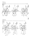
- Fig. 1 einen Axialschnitt durch ein Spannfutter nach der Erfindung,
- Fig. 2 eine Stirnansicht des Spannfutters nach Fig. 1 von vorn, teils geschnitten längs der in Fig. 1 mit II - II bezeichneten Linie,
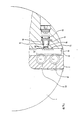
- Fig. 3 das in Fig. 1 mit III bezeichnete Detail in gegenüber Fig. 1 vergrößerter Darstellung, und zwar in den Teilfig. 3.1 bis 3.6 in verschiedenen Betriebszuständen des Spannfutters,
- Fig. 4 einen Teil der Fig. 1 in einer anderen Ausführungsform des Spannfutters,
- Fig. 5 den Gegenstand der Fig. 4 in einer der Fig. 2 entsprechenden Darstellung,
- Fig. 6 den Schnitt längs der Linie VI - VI in Fig. 4,
- Fig. 7 einen Axialschnitt durch eine weitere Ausführungsform des erfindungsgemäßen Spannfutters,
- Fig. 8 den Gegenstand der Fig. 7 in einer der Fig. 2 entsprechenden Darstellung mit in Fig. 7 eingetragener Schnittlinie VIII - VIII,
- Fig. 9 den Schnitt in Richtung IX - IX in Fig. 7, und
- Fig. 10 eine nochmals andere Ausführungsform des erfindungsgemäßen Spannfutters in einer den Fig. 2 und 8 entsprechenden Teildarstellung.
- 1 is an axial section through a chuck according to the invention,
- 2 shows an end view of the chuck according to FIG. 1 from the front, partly in section along the line designated II - II in FIG. 1,
- Fig. 3 shows the detail designated in Fig. 1 with III in an enlarged view compared to Fig. 1, in the Teilfig. 3.1 to 3.6 in different operating states of the chuck,
- 4 shows a part of FIG. 1 in another embodiment of the chuck,
- 5 shows the subject of FIG. 4 in a representation corresponding to FIG. 2,
- 6 shows the section along the line VI - VI in FIG. 4,
- 7 shows an axial section through a further embodiment of the chuck according to the invention,
- 8 shows the subject of FIG. 7 in a representation corresponding to FIG. 2 with section line VIII-VIII entered in FIG. 7,
- Fig. 9 shows the section in the direction IX - IX in Fig. 7, and
- 10 shows yet another embodiment of the chuck according to the invention in a partial representation corresponding to FIGS. 2 and 8.
Das in den Fig. 1 und 2 dargestellte kraftbetätigte Spannfutter besitzt drei radial verstellbare Spannbacken, deren jede aus einer in einem Futterkörper 1 geführten antreibbaren Grundbacke 2 und einer an der Stirnfläche der Grundbacke 2 angeordneten, in der Zeichnung der Einfachheit wegen nicht dargestellten Aufsatzbacke besteht. Der Antrieb der Grundbacken 2 erfolgt mittels eines axial im Futterkörper 1 verstellbaren Antriebsgliedes 4 über eine Keilhakenverbindung 5 üblicher Art. Jedoch ist im Rahmen der Erfindung selbstverständlich auch jeder andere Stellantrieb für die Grundbacken 2 möglich. Die Aufsatzbacken sind, wie in im wesentlichen gleicher Weise schon in der DE-PS 35 10 457 ausführlich beschrieben, auswechselbar an den Grundbacken 2 befestigt, wobei die Grundbacken 2 und die Aufsatzbacken jeweils in einer Verzahnung 6 mit quer zur Führungsrichtung der Grundbacken 2 verlaufenden Zahnleisten im gegenseitigen Eingriff stehen. Die Verbindung zwischen der Aufsatzbacke und der Grundbacke 2 erfolgt durch zwei Verbindungszapfen 7 mit zur Futterachse 8 paralleler Zapfenachse 9. Diese Verbindungszapfen 7 sind in der Verstellrichtung der Grundbacke 2 mit Abstand nebeneinander angeordnet. Jeder Verbindungszapfen 7 ist mit seinem futterseitigen, ein Gewinde tragenden Zapfenende in einem Muttergewinde 11 der Grundbacke 2 geführt. Am anderen Ende trägt der Verbindungszapfen 7 einen Riegelkopf 12, der in zwei zueinander und zur Zapfenachse 9 senkrechten Richtungen unterschiedliche Abmessungen besitzt, in der einen Richtung also schmaler und in der anderen breiter ist und in dieser Richtung über den Zapfenschaft auswärts vorstehende Riegelschultern 3 bildet. Dieser Riegelkopf 12 greift in eine in der Aufsatzbacke vorgesehene Riegelaufnahme, wobei der Riegelkopf in der dem Entriegelungszustand entsprechenden Drehlage des Verbindungszapfens 7 axial in die Riegelaufnahme einsteckbar ist und in der dem Verriegelungszustand entsprechenden, um 90° gedrehten Drehlage mit seinen Riegelschultern 3 eine in der Riegelaufnahme vorgesehene Hinterschneidung axial formschlüssig hinterfaßt. Die Fig. 1 und 2 zeigen die Verbindungszapfen 7 in ihrer jeweils dem Verriegelungszustand entsprechenden Drehlage. Ferner besitzt jeder Verbindungszapfen 7 an seinem in der Grundbacke 2 befindlichen Teil eine Verzahnung 20 nach Art eines Zahnritzels. Quer zur Zapfenachse 9 längsverschieblich in der Grundbacke 2 geführte Steuerstangen 10, 10ʹ besitzen eine mit der Verzahnung 20 des Verbindungszapfens 7 kämmende Querverzahnung 21 nach Art einer Zahnleiste, so daß die Verschiebung der Steuerstangen 10, 10ʹ in ihrer Längsrichtung zu entsprechenden Drehbewegungen des Verbindungszapfens 7 führt. Werden die Verbindungszapfen 7 in die Ver riegelungsstellung gedreht, erfahren sie über ihr Gewinde 11 einen axialen Anzug, durch den die Aufsatzbacke axial gegen die Grundbacke 2 gezogen wird. Gleichzeitig wird das Drehmoment für das Verdrehen der Verbindungszapfen 7 in die endgültige Verriegelungsstellung entsprechend dem axialen Anzug erheblich größer, als bei noch oder schon lockeren Verbindungszapfen zu deren kraftarmen Verdrehen erforderlich ist.The power-operated chuck shown in FIGS. 1 and 2 has three radially adjustable clamping jaws, each of which consists of a
Die Führung der Steuerstangen 10, 10ʹ verläuft in der Grundbacke 2 parallel zur Führung der Grundbacke 2 im Futterkörper 1. Für die Steuerstangen 10, 10ʹ ist ein Steuerglied 13 vorgesehen, durch das die Steuerstangen 10, 10ʹ gegen Verschiebungen in Bezug auf den Futterkörper 1 festgestellt werden können. Die Grundbacken 2 sind durch ihr Antriebsglied 4 auch bei festgestellten Steuerstangen 10, 10ʹ zum Verdrehen der Verbindungszapfen 7 verschiebbar. Im Ergebnis kann der Spannhub der Grundbacken 2 dazu verwendet werden, bei jeweils festgestellten Steuerstangen 10, 10ʹ durch die sich dann ergebende Relativverschiebung zwischen jeweils der Steuerstange 10, 10ʹ und der Grundbacke 2 die Verbindungszapfen 7 kraftstark vollständig in die Verriegelungsstellung hineinzudrehen, bzw. zum Lockern der Backenverbindung aus der Verriegelungsstellung herauszudrehen.The guidance of the
In den Fig. 1 bis 9 ist das Steuerglied 13 ein im Futterkörper 1 quer zur Führungsrichtung der Steuerstangen 10, 10ʹ geführtes, kraftbetätigt bewegbares Stellglied, das mindestens eine längs seines Stellweges erstreckende Steuerkurve 14 aufweist, die einen Anschlag für die Steuerstangen 10, 10ʹ bildet und mittels der bei der Verstellung des Steuergliedes 13 die Steuerstangen 10, 10ʹ in Bezug auf die von ihrem Antriebsglied 4 festgehaltene Grundbacke 2 verschiebbar sind.1 to 9, the
Im Ausführungsbeispiel nach den Fig. 1 bis 3 ist das Steuerglied 13 ein im Futterkörper 1 axial und konzentrisch geführter, über ein Stellrohr 35 verstellbarer Steuerkolben. Für jede Grundbacke 2 sind zwei sich am Verbindungszapfen 7 gegenüber liegende und sich zueinander gegenläufig bewegende Steuerstangen 10, 10ʹ vorgesehen. Das Steuerglied 13 besitzt für jede der beiden Steuerstangen 10, 10ʹ eine eigene Steuerkurve 14, 14ʹ. Diesen Steuerkurven 14, 14ʹ liegt die eine Steuerstange 10ʹ nur beim Verriegelungsvorgang, die andere Steuerstange 10 nur beim Entriegelungsvorgang mit jeweils ihrem radial inneren Stangenende an. Wie insbesondere die Fig. 3 erkennen läßt, besitzen die Steuerkurven 14, 14ʹ und die von ihnen gebildeten Anschlagflächen 14.1, 14.1ʹ,welchen die jeweilige Steuerstange 10, 10ʹ bei der immer radial einwärts gerichteten Verriegelungsbewegung oder Entriegelungsbewegung der Grundbacke 2 anliegt, einen radialen Abstand von der Futterachse 8, der überall, d. h. axial längs der Steuerkurven 14, 14ʹ und des Steuerglieds 13, etwas kleiner ist als der beim Werkstückspannen auftretende kleinste radiale Abstand der Grundbacken 2 bzw. Steuerstangen 10, 10ʹ von der Futterachse 8. In Fig. 3 ist der radial größte Abstand der Grundbacken 2 von der Futterachse 8 durch den Doppelpfeil 16, der radial kleinste Abstand durch den Doppelpfeil 22 gekennzeichnet. Der durch den Doppelpfeil 15 angedeutete Radialhub, den die Grundbacken 2 zum kraftstarken Schließen oder Öffnen der Backenverbindung ausführen müssen, ist demnach etwas größer als der größtzulässige Spannhub der Grundbacken 2. Das Steuerglied 13 ist im Futterkörper 1 mit einem radialen Verschiebungsspiel 17 zum Kraftausgleich zwischen den Steuerstangen 10, 10ʹ aller Grundbacken 2 angeordnet und nur in seiner der völlig offenen Backenverbindung entsprechenden, also in Fig. 1 völlig zurückgezogenen Axialstellung in eine das Radialspiel ausschaltende Zentrierbohrung 19 im Futterkörper 1 verschoben. Diese Zentrierung des Steuerglieds 13 bewirkt, daß die die Entriegelung bewirkenden Steuerstangen 10 über die ihnen zugeordneten Anschlagflächen 14.4 sämtlich in übereinstimmender radialer Position stehen und damit alle Verbindungszapfen 7 vollständig in ihre der Entriegelung entsprechende Drehlage verdreht sind, so daß der Zapfenkopf 12 an den Aufsatzbacken austreten kann, die Aufsatzbacken also axial von den Verbindungszapfen 7 abgenommen, bzw. ihnen aufgesteckt werden können. Der Anschlagfläche 14.1ʹ an der Steuerkurve 14ʹ für den Verriegelungsvorgang entspricht an der Steuerkurve 14 für den Entriegelungsvorgang eine Ausnehmung 14.2 zum freien Eintritt des Endes der ihr zugeordneten Steuerstange 10. Die an diese Ausnehmung 14.2 anschließende Anschlagfläche 14.1 der Steuerkurve 14 ist um mindestens den dem Doppelpfeil 15 entsprechenden Hub radial höher, den die Grundbacke 2 zum Öffnen der Backenverbindung ausführen muß. Die Steuerkurven 14, 14ʹ besitzen im übrigen Abschnitte 14.3, 14.3ʹ, die als gegen die Futterachse 8 geneigte ebene Keilflächen ausgebildet sind. Diesen Abschnitten liegen die Steuerstangen 10, 10ʹ mit entsprechend geneigten Schrägflächen 18, 18ʹ an.In the exemplary embodiment according to FIGS. 1 to 3, the
Die Funktionsweise des in den Fig. 1 und 2 dargestellten Futters läßt sich anhand von Fig. 3 wie folgt erläutern: Die Steuerstange 10ʹ bewirkt die Verriegelung, die Steuerstange 10 die Entriegelung. Der in Fig. 3.1 dargestellte Zustand entspricht der Entriegelungsstellung der Verbindungszapfen 7. Die zur Verriegelung dienende Steuerstange 10ʹ ist radial nach innen verschoben und liegt an der Steuerkurve 14ʹ an. Wird jetzt das Steuerglied 13 in Richtung des Pfeiles 13.1 axial nach vorn verschoben, wird die Steuerstange 10ʹ radial nach außen geschoben, bis ihr Stangenende auf die Anschlagfläche 14.1ʹ aufläuft, wie dies in Fig. 3.2 dargestellt ist. Nun wird entsprechend Fig. 3.3 die Grundbacke 2 radial einwärts verstellt, wie dies durch den Pfeil 2.2 angedeutet ist. Dadurch ergibt sich eine weitere Relativverschiebung zwischen der Steuerstange 10ʹ und der Grundbacke 2 mit dem Ergebnis, daß die Steuerstange 10ʹ und die Verbindungszapfen 7 vollständig in ihre dem Verriegelungszustand entsprechende Stellung verschoben bzw. verdreht werden, und zwar unter der hohen Spannkraft der Grundbacke 2. Die Grundbacke 2 kann nun mit der an ihr verriegelten Aufsatzbacke radial durch das Antriebsglied 4 zum Spannen eines Werkstücks verstellt werden, wobei der kleinste Spannradius etwas größer sein soll als der durch den Doppelpfeil 22 angedeutete Radius, bis zu dem die Grundbacken 2 auf ihrem durch den Doppelpfeil 15 angedeuteten Radialhub beim kraftstarken Schließen und Öffnen der Backenverbindung verstellbar sind. Daher können beim Spannen des Werkstücks weder die Steuerstange 10ʹ noch die Grundbacke 2 mit ihrem jeweils radial inneren Ende am Steuerglied 13 anstoßen. - Bei diesem Verriegelungsvorgang ist die der Entriegelung dienende Steuerstange 10 in die Ausnehmung 14.2 eingetreten, wie dies in Fig. 3.3 strichpunktiert angedeutet ist. Zur Entriegelung wird zunächst die Grundbacke 2 entsprechend dem Pfeil 2.3 radial auswärts auf den größten Stellradius 16 gefahren und anschließend das Steuerglied 13 entsprechend dem Pfeil 13.2 axial soweit zurückgezogen, daß sich das Ende der Steuerstange 10 über der Anschlagfläche 14.1 befindet. Dieser Zustand ist in Fig. 3.4 dargestellt. Um nun die Verbindungszapfen 7 aus ihrem Verriegelungszustand zu lockern, wird die Grundbacke 2 entsprechend Fig. 3.5 in Richtung des Pfeiles 2.4 radial einwärts bewegt, wobei die an der Anschlagfläche 14.2 festgehaltene Steuerstange 10 stehen bleibt. Dadurch ergibt sich unter der hohen Spannkraft der Grundbacke 2 eine Relativverschiebung zwischen der Steuerstange 10 und der Grundbacke 2, die die Verbindungszapfen 7 soweit verdreht, daß deren weitere Verdrehung in die der Entriegelungsstellung entsprechende Drehlage ohne weiteren großen Kraftaufwand erfolgen kann. Zu letzterem dient wiederum das Steuerglied 13, das entsprechend Fig. 3.6 in Richtung des Pfeiles 13.3 axial weiter zurückgezogen wird, wobei die Steuerstange 10 sich weiter radial auswärts bewegt, bis sie auf der Anschlagfläche 14.4 aufsitzt. Gleichzeitig ist das Steuerglied 13 in die Zentrierbohrung 19 eingetreten, so daß alle Steuerstangen 10 der drei Grundbacken 2 radial exakt die gleiche Stellung besitzen, also die Verbindungszapfen 7 voll in den Entriegelungszustand verdreht sind. Bei diesem Entriegelungsvorgang hat sich die der Verriegelung dienende Steuerstange 10ʹ radial einwärts verschoben, wie dies in Fig. 3.6 wiederum strichpunktiert angedeutet ist. Wird nun die Grundbacke 2 mit der Steuerstange 10 entsprechend dem Pfeil 2.5 wieder radial auswärts in die dem größten Radius 16 entsprechende Stellung bewegt, ergibt sich der in Fig. 3.1 dargestellte Ausgangszustand.The operation of the chuck shown in FIGS. 1 and 2 can be explained with reference to FIG. 3 as follows: the control rod 10ʹ causes the locking, the
Die Ausführungsform nach den Fig. 4 bis 6 unterscheidet sich von dem eben beschriebenen Spannfut ter lediglich dadurch, daß jede der Steuerstangen 10, 10ʹ doppelt, nämlich je ein eigenes Steuerstangenpaar für jeden Verbindungszapfen 7 vorgesehen ist. Diese jeweils beiden Steuerstangen 10.1, 10.2, bzw. 10.1ʹ, 10.2ʹ sind in Verschiebungsrichtung durch ein Kraftausgleichsglied 23 miteinander gekoppelt und nicht unmittelbar, sondern über das Kraftausgleichsglied 23 durch das den beiden Steuerstangen gemeinsame Steuerglied 13 feststellbar. Das Kraftausgleichsglied 23 ist als gleicharmiger Heben ausgebildet, der mit den Enden seiner Hebelarme an die beiden Steuerstangen 10.1, 10.2 bzw. 10.1ʹ, 10.2ʹ gelenkig angeschlossen ist und drehbar um die Hebelmitte an eine parallel zu den Steuerstangen in der Grundbacke 2 geführte Stellstange 24 angeschlossen ist, an der das Steuerglied 13 angreift. Da die Steuerstangen nur auf Druck beansprucht werden, ist das Kraftausgleichsglied 23 einerseits mit Drucknasen 23.1 stirnseitig gegen je eine der beiden Steuerstangen 10.1, 10.2 bzw. 10.1ʹ, 10.2ʹ und andererseits über eine seine Drehung ermöglichende Zylinderfläche 23.2 gegen die Stellstange 24 abgestützt. Die beiden Steuerstangen 10.1, 10.2 bzw. 10.1ʹ, 10.2ʹ sind in Richtung der Zapfenachse 9 unmittelbar aneinander geführt und mit je einer Längsaussparung 25 versehen, die an jeder Steuerstange das jeweils nicht mit ihr im Eingriff stehende Zahnritzel 20 über den Verstellweg der Steuerstange aufnimmt. Es wird auf diese Weise sicher gestellt, daß die beiden Verbindungszapfen 7 jeder Grundbacke 2 mit gleicher Kraft und vollständig bis in ihre jeweiligen, dem Verriegelungs- bzw. Entriegelungszustand entsprechende Drehlage verstellt werden.The embodiment according to FIGS. 4 to 6 differs from the chuck just described ter only in that each of the
Im Ausführungsbeispiel nach den Fig. 7 bis 9 ist an jeder Grundbacke 2 nur eine einzige Steuerstange 10 vorgesehen. Das Steuerglied 13 ist eine Ringscheibe, die in einer konzentrischen Ringnut 26 des Futterkörpers 1 drehbar um die Futterachse 8 gelagert ist. Der Drehantrieb erfolgt über ein Stellrohr 27 durch einen nicht dargestellten hydraulischen oder pneumatischen Drehkolben. Die Ringnut 26 ist zu den Grundbacken 2 hin offen. An jeder Grundbacke 2 ist die Steuerstange 10 in einer zur Ringnut 26 hin offenen Nut 28 geführt. Die Ringscheibe besitzt auf ihrer den Grundbacken 2 zugewandten Seite die Steuerkurve 14, der die Steuerstange 10 mit einem Anschlagglied 29 anliegt. In der aus Fig. 8 ersichtlichen Drehlage bildet das Steuerglied 13 einen in der Führungsrichtung der Steuerstange 10 verlaufenden freien Durchgang für das Anschlagglied 19. In dieser Drehlage ist also die Spannbewegung der Grundbacke 2 nicht durch das Steuerglied 13 behindert. An diesen freien Durchgang schließt in beiden Drehrichtungen das Steuerglieds 13 die Steuerkurve 14 mit je einem Kurvenzweig an, von welchen der Kurvenzweig 14a die Verriegelungsbewegung, der andere Kurvenzweig 14b die Entriegelungsbewegung der Steuerstange steuern. Jeder dieser beiden Kurvenzweige 14a, 14b bildet einen Anschlag 30a, 30b, an dem die Steuerstange 10 in Richtung der Verriegelungsbewegung bzw. Entriegelungsbewegung der Grundbacke 2 festgehalten ist.In the exemplary embodiment according to FIGS. 7 to 9, only a
Die Funktionsweise dieses Spannfutters läßt sich wie folgt beschreiben: Zur Verriegelung fährt die Grundbacke 2 nach innen, wobei das Anschlagglied 29 der Steuerstange 10 aus der Stellung 29.1 in die Stellung 29.2 gelangt. Als nächstes wird das Steuerglied 13 um den Winkel α nach rechts verdreht, wodurch das Anschlagglied 29 über die Steuerkurve 14a aus der Stellung 29.2 in die Stellung 29.4 verschoben wird. Nun fährt die Grundbacke 2 nach außen, wobei das Anschlagglied 29 und damit die Steuerstange 10 am Anschlag 30a festgehalten werden, so daß die Verbindungszapfen 7 mit der hohen Spannkraft der Grundbacke 2 in die Verriegelungsstellung gedreht werden. Die Backenverbindung ist damit geschlossen. Dreht nun das Steuerglied 13 um den Winkel α nach links in die Ausgangsstellung, sind die freien Spannbewegungen der Grundbacken 2 wieder möglich. - Zur Entriegelung fährt die Grundbacke 2 zunächst nach außen, wodurch das Anschlagglied 29 und entsprechend die Steuerstange 10 in die Stellung 29.3 gelangen. Das Steuerglied 13 dreht nun um den Winkel β nach links, so daß der Anschlag 30b unter das Anschlagglied 29 gelangt. Anschließend fährt die Grundbacke 2 nach innen, wobei das Anschlagglied 29 und damit die Steuerstange 10 am Anschlag 30b gehalten werden, so daß sich die Verbindungszapfen 7 aus ihrer Verriegelungsstellung unter der hohen Spannkraft der Grundbacken 2 lösen. Das Steuerglied 13 dreht nun weiter um den Winkel γ nach links, wodurch das Anschlagglied 29 und damit die Steuerstange 10 über die Steuerkurve 14b von der Stellung 29.3 in die Stellung 29.1 gelangen. Durch diese Verschiebung der Steuerstange 10 schwenken die Verbindungszapfen 7 in ihre der völligen Entriegelung entsprechende Drehstellung und geben die Aufsatzbacke frei. Anschließend kann das Steuerglied 13 um die Winkel β und γ nach rechts in die Ausgangsstellung zurückgedreht werden.The operation of this chuck can be described as follows: To lock the
Im Ausführungsbeispiel nach Fig. 10 ist das Steuerglied 13 ein im Futterkörper 1 geführter Riegel, der in der in der Figur gezeigten Verriegelungsstellung mit einem Riegelkopf 30 form- und kraftschlüssig in Riegelaufnahmen 31 der Steuerstange 10 quer zu deren Führungsrichtung eingreift. Im einzelnen ist die Steuerstange 10 in einer zum Futterkörper 1 hin offenen Nut 32 der Grundbacke 2 geführt und auf der offenen Nutseite mit einer die Riegelaufnahmen 31 bildenden Zahnleiste versehen. Der Riegel ist ein in seiner Längsrichtung kraftbetätigt mittels eines hydraulisch oder pneumatisch beaufschlagbaren Kolberns 33 hin und her verschiebbarer zylindrischer Bolzen, der durch seitliche Führungsansätze, die in entsprechenden Nuten 34 des Futterkörpers 1 laufen, gegen Verdrehen um seine Achse 35 gesichert ist, so daß die an seiner der Steuerstange 10 zugewandten Stirn als Riegelkopf 30 dienende , in die Zahnleiste passende Querverzahnung stets entsprechend dem Zahnverlauf an der Zahnleiste ausgerichtet ist.In the exemplary embodiment according to FIG. 10, the
Die Funktionsweise dieser Ausführungsform läßt sich kurz wie folgt beschreiben: Zur Verriegelung fährt die Grundbacke 2 in die äußerste Stellung. Das Steuerglied 13 wird durch den Kraftkolben 33 in die in der Zeichnung dargestellte Eingriffsstellung an der Steuerstange 10 bewegt. Anschließend fährt die Grundbacke 2 um den größtmöglichen Spannhub radial nach innen, wobei der Steuerstange 10 durch das Steuerglied 13 festgehalten wird, so daß sich zwischen der Steuerstange 10 und der Grundbacke 2 eine Relativverschiebung ergibt, welche die Verbindungszapfen 7 in dem der Verriegelungsbewegung entsprechenden Drehsinn verdreht. Nun fährt das Steuerglied 13, betätigt durch den Kolben 33, aus dem Eingriff zurück und gibt die Steuerstange 10 frei. In diesem Zustand fährt die Grundbacke 2 in ihre äußere Stellung zurück und nimmt dabei die Steuerstange 10 mit, so daß keine Rückverdrehung der Verbindungszapfen 7 erfolgt. Der beschriebene Ablauf kann nun wiederholt werden, wodurch sich eine weitere Relativverschiebung zwischen Steuerstange 10 und Grundbacke 2 im Sinne einer Verriegelungsbewegung der Verbindungsstange 10 ergibt. Diese Wieder holung wird so oft durchgeführt, bis die Verbindungszapfen 7 aus ihrer Entriegelungslage über 90° in ihre Verriegelungslage gedreht sind. - Der Entriegelungsvorgang erfolgt sinngemäß im umgekehrter Reihenfolge.The operation of this embodiment can be briefly described as follows: the
Claims (15)
Priority Applications (1)
| Application Number | Priority Date | Filing Date | Title |
|---|---|---|---|
| AT87119164T ATE53316T1 (en) | 1987-02-11 | 1987-12-23 | POWER ACTUATED CHUCK. |
Applications Claiming Priority (2)
| Application Number | Priority Date | Filing Date | Title |
|---|---|---|---|
| DE19873704135 DE3704135A1 (en) | 1987-02-11 | 1987-02-11 | POWERED CHUCK |
| DE3704135 | 1987-02-11 |
Publications (2)
| Publication Number | Publication Date |
|---|---|
| EP0278111A1 true EP0278111A1 (en) | 1988-08-17 |
| EP0278111B1 EP0278111B1 (en) | 1990-06-06 |
Family
ID=6320695
Family Applications (1)
| Application Number | Title | Priority Date | Filing Date |
|---|---|---|---|
| EP87119164A Expired - Lifetime EP0278111B1 (en) | 1987-02-11 | 1987-12-23 | Power chuck |
Country Status (7)
| Country | Link |
|---|---|
| US (1) | US4877259A (en) |
| EP (1) | EP0278111B1 (en) |
| JP (1) | JPS63200901A (en) |
| AT (1) | ATE53316T1 (en) |
| BR (1) | BR8800546A (en) |
| DE (2) | DE3704135A1 (en) |
| ES (1) | ES2016329B3 (en) |
Families Citing this family (6)
| Publication number | Priority date | Publication date | Assignee | Title |
|---|---|---|---|---|
| US5100846A (en) | 1990-09-13 | 1992-03-31 | The Dow Chemical Company | Purification of carbothermally produced aluminum nitride |
| US5354598A (en) * | 1992-04-10 | 1994-10-11 | Minnesota Mining And Manufacturing Company | Article capable of displaying defined images |
| US5218890A (en) * | 1992-06-03 | 1993-06-15 | Christ Jr William H | Keyless adjustable driver |
| US6257595B1 (en) | 1998-09-04 | 2001-07-10 | Hardinge Inc. | Collect chuck with quick-change cap |
| DE19930784B4 (en) * | 1999-07-03 | 2008-11-27 | Röhm Gmbh | Chucks for machine tools |
| HU226381B1 (en) * | 2004-08-25 | 2008-10-28 | Jozsef Dr Tajnafoei | Chucking device for flexible production |
Citations (2)
| Publication number | Priority date | Publication date | Assignee | Title |
|---|---|---|---|---|
| DE3501325A1 (en) * | 1985-01-17 | 1986-07-17 | SMW Schneider & Weißhaupt GmbH, 7996 Meckenbeuren | CHUCK FOR MACHINE TOOLS |
| DE3519785A1 (en) * | 1985-06-03 | 1986-12-18 | SMW Schneider & Weißhaupt GmbH, 7996 Meckenbeuren | DEVICE FOR COUPLING TOP CLAMPING JAWS WITH BASE JAWS OF A CHUCK |
Family Cites Families (6)
| Publication number | Priority date | Publication date | Assignee | Title |
|---|---|---|---|---|
| DE2533803C3 (en) * | 1975-07-29 | 1983-12-29 | Röhm, Günter Horst, 7927 Sontheim | Power operated wedge chuck |
| DE2711904C3 (en) * | 1977-03-18 | 1981-08-13 | Röhm, Günter Horst, 7927 Sontheim | Chuck for lathes |
| DE2960619D1 (en) * | 1978-05-19 | 1981-11-12 | Roehm Guenter H | Chuck for turning machines |
| EP0008318B1 (en) * | 1978-08-18 | 1981-04-29 | Günter Horst Röhm | Chuck for turning machines |
| DE2930721C2 (en) * | 1979-07-28 | 1985-08-01 | Günter Horst 7927 Sontheim Röhm | Chuck with adjustable jaws radially to the chuck axis in a chuck body |
| DE3005459A1 (en) * | 1980-02-14 | 1981-08-20 | Paul Forkardt KG, 4000 Düsseldorf | CHUCK FOR LATHE |
-
1987
- 1987-02-11 DE DE19873704135 patent/DE3704135A1/en not_active Withdrawn
- 1987-12-23 AT AT87119164T patent/ATE53316T1/en not_active IP Right Cessation
- 1987-12-23 EP EP87119164A patent/EP0278111B1/en not_active Expired - Lifetime
- 1987-12-23 DE DE8787119164T patent/DE3763017D1/en not_active Expired - Lifetime
- 1987-12-23 ES ES87119164T patent/ES2016329B3/en not_active Expired - Lifetime
-
1988
- 1988-01-25 US US07/147,716 patent/US4877259A/en not_active Expired - Fee Related
- 1988-02-10 BR BR8800546A patent/BR8800546A/en not_active IP Right Cessation
- 1988-02-12 JP JP63031688A patent/JPS63200901A/en active Granted
Patent Citations (2)
| Publication number | Priority date | Publication date | Assignee | Title |
|---|---|---|---|---|
| DE3501325A1 (en) * | 1985-01-17 | 1986-07-17 | SMW Schneider & Weißhaupt GmbH, 7996 Meckenbeuren | CHUCK FOR MACHINE TOOLS |
| DE3519785A1 (en) * | 1985-06-03 | 1986-12-18 | SMW Schneider & Weißhaupt GmbH, 7996 Meckenbeuren | DEVICE FOR COUPLING TOP CLAMPING JAWS WITH BASE JAWS OF A CHUCK |
Also Published As
| Publication number | Publication date |
|---|---|
| BR8800546A (en) | 1988-09-27 |
| ATE53316T1 (en) | 1990-06-15 |
| US4877259A (en) | 1989-10-31 |
| DE3704135A1 (en) | 1988-08-25 |
| ES2016329B3 (en) | 1990-11-01 |
| EP0278111B1 (en) | 1990-06-06 |
| JPH0457442B2 (en) | 1992-09-11 |
| JPS63200901A (en) | 1988-08-19 |
| DE3763017D1 (en) | 1990-07-12 |
Similar Documents
| Publication | Publication Date | Title |
|---|---|---|
| EP0241798B1 (en) | Pincers for crimping electrical terminals, cable connectors and the like onto electrical leads, light wave guides, etc | |
| EP0302992B1 (en) | Post-clamping chuck | |
| DE10114480C2 (en) | Swivel actuator with three stop positions | |
| DE3638526C1 (en) | Workpiece clamping device that can be driven by an electric motor | |
| DE2710746B2 (en) | Tire building drum | |
| EP3507060B1 (en) | Coupling device | |
| DE855785C (en) | Electromechanical screw jack | |
| DE2619569A1 (en) | DEVICE FOR ADJUSTMENT OF A TOOL HOLDER IN AUTOMATIC TURNING HEADS FOR LATHE OR SIMILAR MACHINERY | |
| EP0278111B1 (en) | Power chuck | |
| DE10259959B4 (en) | Power chuck and wedge bar for it | |
| DE2556227B2 (en) | Chuck | |
| EP0416612B1 (en) | Turret for automatic lathe with tool holder for driven rotating tools | |
| EP0195184B1 (en) | Jaw-changing device | |
| EP0576837A1 (en) | Injection mouding machine with stack mould | |
| DE3410967C2 (en) | ||
| DE2407554A1 (en) | REVOLVER HEAD | |
| DE1783026C3 (en) | Power operated pipe wrench | |
| CH619384A5 (en) | ||
| DE102006009432B4 (en) | Gripping device for a tool changing device | |
| DE19960932A1 (en) | Linear actuator for adjustment of movable element e.g. to a patient lifter | |
| DE3318941A1 (en) | DEVICE FOR ROTATING AND AXIAL MOVING BOLTS | |
| DE898839C (en) | Device and method for the arbitrary elimination and activation of the dead gear in spindle drives | |
| DE3709299A1 (en) | Tool-changing device for a machine tool | |
| DE19730053C1 (en) | Spreader for pipe ends | |
| EP0313035A2 (en) | Closing device for an injection moulding machine |
Legal Events
| Date | Code | Title | Description |
|---|---|---|---|
| PUAI | Public reference made under article 153(3) epc to a published international application that has entered the european phase |
Free format text: ORIGINAL CODE: 0009012 |
|
| 17P | Request for examination filed |
Effective date: 19880603 |
|
| AK | Designated contracting states |
Kind code of ref document: A1 Designated state(s): AT CH DE ES FR GB IT LI SE |
|
| 17Q | First examination report despatched |
Effective date: 19891115 |
|
| GRAA | (expected) grant |
Free format text: ORIGINAL CODE: 0009210 |
|
| AK | Designated contracting states |
Kind code of ref document: B1 Designated state(s): AT CH DE ES FR GB IT LI SE |
|
| REF | Corresponds to: |
Ref document number: 53316 Country of ref document: AT Date of ref document: 19900615 Kind code of ref document: T |
|
| REF | Corresponds to: |
Ref document number: 3763017 Country of ref document: DE Date of ref document: 19900712 |
|
| ET | Fr: translation filed | ||
| ITF | It: translation for a ep patent filed |
Owner name: STUDIO JAUMANN |
|
| GBT | Gb: translation of ep patent filed (gb section 77(6)(a)/1977) | ||
| PLBE | No opposition filed within time limit |
Free format text: ORIGINAL CODE: 0009261 |
|
| STAA | Information on the status of an ep patent application or granted ep patent |
Free format text: STATUS: NO OPPOSITION FILED WITHIN TIME LIMIT |
|
| 26N | No opposition filed | ||
| ITTA | It: last paid annual fee | ||
| PGFP | Annual fee paid to national office [announced via postgrant information from national office to epo] |
Ref country code: SE Payment date: 19941212 Year of fee payment: 8 Ref country code: GB Payment date: 19941212 Year of fee payment: 8 |
|
| PGFP | Annual fee paid to national office [announced via postgrant information from national office to epo] |
Ref country code: FR Payment date: 19941215 Year of fee payment: 8 |
|
| PGFP | Annual fee paid to national office [announced via postgrant information from national office to epo] |
Ref country code: CH Payment date: 19941220 Year of fee payment: 8 |
|
| PGFP | Annual fee paid to national office [announced via postgrant information from national office to epo] |
Ref country code: ES Payment date: 19941227 Year of fee payment: 8 |
|
| PGFP | Annual fee paid to national office [announced via postgrant information from national office to epo] |
Ref country code: AT Payment date: 19941230 Year of fee payment: 8 |
|
| EAL | Se: european patent in force in sweden |
Ref document number: 87119164.9 |
|
| PGFP | Annual fee paid to national office [announced via postgrant information from national office to epo] |
Ref country code: DE Payment date: 19950211 Year of fee payment: 8 |
|
| PG25 | Lapsed in a contracting state [announced via postgrant information from national office to epo] |
Ref country code: GB Effective date: 19951223 Ref country code: AT Effective date: 19951223 |
|
| PG25 | Lapsed in a contracting state [announced via postgrant information from national office to epo] |
Ref country code: SE Effective date: 19951224 |
|
| PG25 | Lapsed in a contracting state [announced via postgrant information from national office to epo] |
Ref country code: ES Free format text: LAPSE BECAUSE OF THE APPLICANT RENOUNCES Effective date: 19951226 |
|
| PG25 | Lapsed in a contracting state [announced via postgrant information from national office to epo] |
Ref country code: LI Effective date: 19951231 Ref country code: CH Effective date: 19951231 |
|
| GBPC | Gb: european patent ceased through non-payment of renewal fee |
Effective date: 19951223 |
|
| REG | Reference to a national code |
Ref country code: CH Ref legal event code: PL |
|
| PG25 | Lapsed in a contracting state [announced via postgrant information from national office to epo] |
Ref country code: FR Effective date: 19960830 |
|
| PG25 | Lapsed in a contracting state [announced via postgrant information from national office to epo] |
Ref country code: DE Effective date: 19960903 |
|
| REG | Reference to a national code |
Ref country code: FR Ref legal event code: ST |
|
| REG | Reference to a national code |
Ref country code: ES Ref legal event code: FD2A Effective date: 20010402 |
|
| PG25 | Lapsed in a contracting state [announced via postgrant information from national office to epo] |
Ref country code: IT Free format text: LAPSE BECAUSE OF NON-PAYMENT OF DUE FEES;WARNING: LAPSES OF ITALIAN PATENTS WITH EFFECTIVE DATE BEFORE 2007 MAY HAVE OCCURRED AT ANY TIME BEFORE 2007. THE CORRECT EFFECTIVE DATE MAY BE DIFFERENT FROM THE ONE RECORDED. Effective date: 20051223 |