EP0241353A1 - Änderungen an Antischwingungslagern vom hydraulischen Typ - Google Patents
Änderungen an Antischwingungslagern vom hydraulischen Typ Download PDFInfo
- Publication number
- EP0241353A1 EP0241353A1 EP87400708A EP87400708A EP0241353A1 EP 0241353 A1 EP0241353 A1 EP 0241353A1 EP 87400708 A EP87400708 A EP 87400708A EP 87400708 A EP87400708 A EP 87400708A EP 0241353 A1 EP0241353 A1 EP 0241353A1
- Authority
- EP
- European Patent Office
- Prior art keywords
- rigid
- wall
- nozzle
- support
- section
- Prior art date
- Legal status (The legal status is an assumption and is not a legal conclusion. Google has not performed a legal analysis and makes no representation as to the accuracy of the status listed.)
- Granted
Links
Images

Classifications
-
- F—MECHANICAL ENGINEERING; LIGHTING; HEATING; WEAPONS; BLASTING
- F16—ENGINEERING ELEMENTS AND UNITS; GENERAL MEASURES FOR PRODUCING AND MAINTAINING EFFECTIVE FUNCTIONING OF MACHINES OR INSTALLATIONS; THERMAL INSULATION IN GENERAL
- F16F—SPRINGS; SHOCK-ABSORBERS; MEANS FOR DAMPING VIBRATION
- F16F13/00—Units comprising springs of the non-fluid type as well as vibration-dampers, shock-absorbers, or fluid springs
- F16F13/04—Units comprising springs of the non-fluid type as well as vibration-dampers, shock-absorbers, or fluid springs comprising both a plastics spring and a damper, e.g. a friction damper
- F16F13/26—Units comprising springs of the non-fluid type as well as vibration-dampers, shock-absorbers, or fluid springs comprising both a plastics spring and a damper, e.g. a friction damper characterised by adjusting or regulating devices responsive to exterior conditions
- F16F13/262—Units comprising springs of the non-fluid type as well as vibration-dampers, shock-absorbers, or fluid springs comprising both a plastics spring and a damper, e.g. a friction damper characterised by adjusting or regulating devices responsive to exterior conditions changing geometry of passages between working and equilibration chambers, e.g. cross-sectional area or length
Definitions
- the invention relates to anti-vibration devices intended to be interposed for the purposes of support and damping between two rigid elements individually subjected to certain oscillations or vibrations, elements such as for example a vehicle chassis and the engine of this vehicle, damping involving the beating of a mass of liquid through a throttled passage hereinafter called "nozzle", at a resonant frequency which is a function of the dimensions of said nozzle and in particular of the ratio between its axial length and its cross section.
- the invention relates more particularly, among the supports of the kind in question, those which consist of a sealed housing interposed between the two rigid elements, housing comprising a rigid base which can be joined to one of the rigid elements, a rigid ring which can be joined to the other rigid element, an elastic annular support wall offering good resistance to axial compression and sealingly connecting the rigid base to the rigid ring and a flexible membrane tightly connected to the rigid ring, the interior of the housing being divided by a partition into two chambers, namely a working chamber situated on the side of the elastic wall and a compensation chamber situated on the side of the flexible membrane, these two chambers communicating with each other permanently by the nozzle , which is generally arranged in the partition wall or around this partition, and being filled with liquid as well as this nozzle.
- the ratio between the length and the average diameter of the nozzle, between 2 and 100, is generally determined once for all according to the frequency F of the oscillations which one wishes to dampen to the maximum.
- Such a formula has the disadvantage that said frequency F is unique: in other words, if it is a question of damping the vibrations of an engine whose frequency varies from 50 to 200 Hz depending on the operating regime of this motor, the supports considered only provide good damping for one of the values of this frequency range and for the values close to F, but not for the other values.
- the length / section ratio of the nozzle is modified by closing more or less a section of this passage forming a rigid annular seat by a rigid valve displaced axially opposite said seat.
- the object of the invention is, above all, to eliminate these drawbacks.
- the hydraulic anti-vibration supports of the type considered are essentially characterized according to the invention in that the nozzle is delimited at least in part by a deformable wall and in that the means for modifying the length / section ratio of said nozzle are arranged to deform said wall.
- the deformable wall is constituted by a piece of the partition, then formed from elastomeric material
- the adjustment means comprise a rigid tie rod connecting a point of this wall to a control member external to the support
- the deformable wall is part of a sealed pocket and the adjustment means are arranged so as to connect this pocket to a source of fluid subjected to adjustable pressure or depression, source external to the support, -
- the pocket is a section of waterproof flexible hose which extends through a hollowed-out passage in the partition wall.
- the invention includes, apart from these main provisions, certain other provisions which are preferably used at the same time and which will be more explicitly discussed below.
- the support considered is intended to be interposed between a rigid support member such as a vehicle chassis and a rigid supported member such as an internal combustion engine.
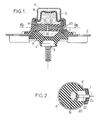
- This support is in the general form of a sealed revolution box around an X axis and comprising, in a manner known per se: an annular frame 1 extended radially by two perforated lugs 2 which can be joined together, in particular by bolting, with the support member, a rigid body 3 here being in the form of a bolt, the threaded portion of which extends downwards, a bolt which can be secured to the supported member, a thick, sealed frustoconical wall 4 of elastomeric material adhered respectively to the frame 1 and to the body 3 and capable of resisting elastically to axial compression and to transverse bending, - And a flexible waterproof membrane 5, the periphery of which is tightly fixed on the annular reinforcement 1.
- a watertight partition 6 divides the interior of the housing into two chambers A and B both filled with liquid, namely a chamber A, for work, arranged on the side of the wall 4 and a chamber B, for compensation, arranged on the side of the membrane 5.
- the partition 6 is constituted by a cylindrical wafer made of elastomer material hollowed out in its central zone by a cylindrical nozzle 19.
- the generatrices of the cylinder defining this nozzle are parallel to the axis X of the support and its cross section has a variable elongated shape comprised between an ellipse (shown in solid lines in FIG. 2) and a bean (mixed lines).
- one of the elongated faces defining the nozzle defines a thinned elastomer wall 20 forming part of the wafer 6.
- a pocket 21 is hollowed out in this wafer so as to form this thinned wall 20.
- This member C passes through openings 23 laterally recessed in the support without affecting the tightness of the two chambers filled with liquid from this support.
- the cross section of the nozzle 19 and therefore the resonant frequency F corresponding to the mass of liquid contained in this nozzle is varied.
- the intermediate partition here designated by the reference 61, is rigid and it is hollowed out axially by a passage 24 of relatively large section.
- This passage is crossed transversely by a section of elastic hose 25, one end of which is closed in leaktight manner by a bearing forming part of the partition 61 and the other end of which is connected in leaktight manner to an external source of a fluid capable of '' be subject to adjustable pressure.
- This section S is all the greater as said pressure is lower and vice versa: in FIG. 6, the profile in phantom 251 of the inflated hose corresponds to a small section S of the nozzle and, on the contrary, the profile in broken lines 252 of the deflated hose corresponds to a large section S.
- the frequency F of the beats to be checked is also linked to said section S.
- Hose 25 is advantageously chosen so such that its deformations as a function of the inflation pressure are oriented perpendicular to the direction of flow of the liquid in the nozzle.
- this hose 25 can be made to communicate in turn with an external source of pressurized fluid and with a pipe for discharging this fluid or for returning said fluid to the source.
- the external source can also be a source of vacuum or "vacuum”.
- the adjustment of the nozzle section can be controlled by the frequency of the oscillations to be damped.
- the above frequency detection is advantageously ensured by detecting the speed of rotation of the motor shaft using a tachometer or appropriate tachometer.
- a tachometer or appropriate tachometer it could also be provided indirectly, by being based on the variations of a parameter linked to said speed such as for example the vacuum prevailing in the intake manifold of the engine.
- hydraulic anti-vibration support capable of being adapted to damping oscillations of different frequencies, even during operation, so as to hold account for instantaneous real needs.
Landscapes
- Engineering & Computer Science (AREA)
- General Engineering & Computer Science (AREA)
- Mechanical Engineering (AREA)
- Combined Devices Of Dampers And Springs (AREA)
Applications Claiming Priority (2)
| Application Number | Priority Date | Filing Date | Title |
|---|---|---|---|
| FR8604929A FR2596837B1 (fr) | 1986-04-07 | 1986-04-07 | Perfectionnements aux supports antivibratoires de type hydraulique |
| FR8604929 | 1986-04-07 |
Publications (2)
| Publication Number | Publication Date |
|---|---|
| EP0241353A1 true EP0241353A1 (de) | 1987-10-14 |
| EP0241353B1 EP0241353B1 (de) | 1989-10-04 |
Family
ID=9333964
Family Applications (1)
| Application Number | Title | Priority Date | Filing Date |
|---|---|---|---|
| EP87400708A Expired EP0241353B1 (de) | 1986-04-07 | 1987-03-31 | Änderungen an Antischwingungslagern vom hydraulischen Typ |
Country Status (4)
| Country | Link |
|---|---|
| US (1) | US4768759A (de) |
| EP (1) | EP0241353B1 (de) |
| DE (1) | DE3760686D1 (de) |
| FR (1) | FR2596837B1 (de) |
Cited By (3)
| Publication number | Priority date | Publication date | Assignee | Title |
|---|---|---|---|---|
| EP0380760A1 (de) * | 1989-02-03 | 1990-08-08 | Firma Carl Freudenberg | Gummilager |
| US6050554A (en) * | 1996-09-24 | 2000-04-18 | Draftex Industries Limited | Vibration damping assemblies |
| GB2342977A (en) * | 1998-10-23 | 2000-04-26 | Draftex Ind Ltd | Hydroelastic engine mount |
Families Citing this family (10)
| Publication number | Priority date | Publication date | Assignee | Title |
|---|---|---|---|---|
| DE3805761A1 (de) * | 1988-02-24 | 1989-09-07 | Daimler Benz Ag | Hydraulisch daempfendes gummilager |
| JPH03503923A (ja) * | 1988-12-22 | 1991-08-29 | ムーグ インコーポレーテツド | 振動を絶縁する機械取付台 |
| JPH0520997A (ja) * | 1991-07-11 | 1993-01-29 | Fuji Electric Co Ltd | 回路遮断器 |
| JPH05223139A (ja) * | 1991-12-20 | 1993-08-31 | Bridgestone Corp | 防振装置 |
| US5704596A (en) * | 1993-08-18 | 1998-01-06 | Bell Helicopter | Vibration isolation system |
| US5435531A (en) * | 1993-08-18 | 1995-07-25 | Bell Helicopter Textron Inc. | Vibration isolation system |
| FR2710957B1 (fr) * | 1993-10-05 | 1995-12-08 | Hutchinson | Perfectionnements aux supports antivibratoires hydrauliques. |
| US6619611B2 (en) * | 2001-07-02 | 2003-09-16 | Newport Corporation | Pneumatic vibration isolator utilizing an elastomeric element for isolation and attenuation of horizontal vibration |
| JP4135719B2 (ja) * | 2004-08-31 | 2008-08-20 | 東海ゴム工業株式会社 | エンジンマウント |
| CN106163839B (zh) * | 2014-03-12 | 2019-03-19 | 哈金森公司 | 装有发电装置的液压防震装置以及用于该防震装置的发电装置 |
Citations (4)
| Publication number | Priority date | Publication date | Assignee | Title |
|---|---|---|---|---|
| DE2428326A1 (de) * | 1974-06-12 | 1976-01-02 | Dornier System Gmbh | Temperaturschwankungen kompensierender schwingungsdaempfer |
| DE3340152A1 (de) * | 1983-02-04 | 1984-08-16 | Toyota Jidosha K.K., Toyota, Aichi | Befestigungsanordnung fuer einen motor-getriebesatz |
| DE3316025A1 (de) * | 1983-05-03 | 1984-11-08 | Tillmann 6108 Weiterstadt Freudenberg | Motorlager |
| EP0155646A2 (de) * | 1984-03-23 | 1985-09-25 | METZELER Gesellschaft mit beschränkter Haftung | Zweikammer-Motorlager mit hydraulischer Dämpfung |
Family Cites Families (15)
| Publication number | Priority date | Publication date | Assignee | Title |
|---|---|---|---|---|
| US2318437A (en) * | 1942-03-28 | 1943-05-04 | Carroll B Vickers | Shock absorber |
| US2457749A (en) * | 1944-05-06 | 1948-12-28 | Gen Tire & Rubber Co | Energy dissipating antivibration device |
| EP0006819B1 (de) * | 1978-07-03 | 1984-06-27 | Automobiles Peugeot | Aufhängungsvorrichtung insbesondere für Fahrzeugmotor |
| US4312493A (en) * | 1979-05-05 | 1982-01-26 | Stauffer Rita A | Apparatus for controlled liquid administration |
| AU523318B2 (en) * | 1980-06-23 | 1982-07-22 | Bridgestone Tire Co. Ltd. | Rubber vibration isolators |
| DE3027742A1 (de) * | 1980-07-22 | 1982-02-04 | Metzeler Kautschuk GmbH, 8000 München | Zweikammer-motorlager mit hydraulischer daempfung |
| DE3048888C2 (de) * | 1980-12-23 | 1982-11-04 | Audi Nsu Auto Union Ag, 7107 Neckarsulm | Vorrichtung zur elastischen Lagerung von Maschinen oder Maschinenteilen, beispielsweise einer Brennkraftmaschine in einem Kraftfahrzeug |
| JPS5854248A (ja) * | 1981-09-25 | 1983-03-31 | Toyota Motor Corp | 防振ゴム装置 |
| JPS5965635A (ja) * | 1982-10-06 | 1984-04-13 | Toyota Motor Corp | 防振ゴム装置 |
| GB2135795B (en) * | 1983-02-09 | 1987-12-16 | Mitsubishi Motors Corp | A rolling control apparatus for an engine |
| US4635897A (en) * | 1983-09-30 | 1987-01-13 | Airsonics License Partnership | Tube flow shut-off device |
| JPS60116937A (ja) * | 1983-11-28 | 1985-06-24 | Toyota Motor Corp | 車輌用内燃機関の防振支持方法 |
| JPS60192195A (ja) * | 1984-03-13 | 1985-09-30 | 日産自動車株式会社 | パワ−ユニツトマウント装置 |
| JPS60234143A (ja) * | 1984-05-03 | 1985-11-20 | Toyoda Gosei Co Ltd | 液体封入防振装置 |
| US4641808A (en) * | 1985-02-22 | 1987-02-10 | Flower Wallace C | Dynamic vibration attenuator utilizing inertial fluid |
-
1986
- 1986-04-07 FR FR8604929A patent/FR2596837B1/fr not_active Expired - Fee Related
-
1987
- 1987-03-31 DE DE8787400708T patent/DE3760686D1/de not_active Expired
- 1987-03-31 EP EP87400708A patent/EP0241353B1/de not_active Expired
- 1987-04-02 US US07/033,189 patent/US4768759A/en not_active Expired - Fee Related
Patent Citations (4)
| Publication number | Priority date | Publication date | Assignee | Title |
|---|---|---|---|---|
| DE2428326A1 (de) * | 1974-06-12 | 1976-01-02 | Dornier System Gmbh | Temperaturschwankungen kompensierender schwingungsdaempfer |
| DE3340152A1 (de) * | 1983-02-04 | 1984-08-16 | Toyota Jidosha K.K., Toyota, Aichi | Befestigungsanordnung fuer einen motor-getriebesatz |
| DE3316025A1 (de) * | 1983-05-03 | 1984-11-08 | Tillmann 6108 Weiterstadt Freudenberg | Motorlager |
| EP0155646A2 (de) * | 1984-03-23 | 1985-09-25 | METZELER Gesellschaft mit beschränkter Haftung | Zweikammer-Motorlager mit hydraulischer Dämpfung |
Non-Patent Citations (1)
| Title |
|---|
| PATENT ABSTRACTS OF JAPAN, vol. 10, no. 100 (M-470)[2157], 16th April 1986; & JP-A-60 234 143 (TOYODA GOSEI K.K.) 20-11-1985 * |
Cited By (3)
| Publication number | Priority date | Publication date | Assignee | Title |
|---|---|---|---|---|
| EP0380760A1 (de) * | 1989-02-03 | 1990-08-08 | Firma Carl Freudenberg | Gummilager |
| US6050554A (en) * | 1996-09-24 | 2000-04-18 | Draftex Industries Limited | Vibration damping assemblies |
| GB2342977A (en) * | 1998-10-23 | 2000-04-26 | Draftex Ind Ltd | Hydroelastic engine mount |
Also Published As
| Publication number | Publication date |
|---|---|
| EP0241353B1 (de) | 1989-10-04 |
| FR2596837B1 (fr) | 1990-06-22 |
| FR2596837A1 (fr) | 1987-10-09 |
| US4768759A (en) | 1988-09-06 |
| DE3760686D1 (en) | 1989-11-09 |
Similar Documents
| Publication | Publication Date | Title |
|---|---|---|
| EP0275503B1 (de) | Dämpfer mit Lastausgleich | |
| EP0304599B1 (de) | Mit Mitteln zur Änderung der Dämpfungscharakteristik ausgerüsteter hydraulischer Stossdämpfer | |
| EP0241353A1 (de) | Änderungen an Antischwingungslagern vom hydraulischen Typ | |
| FR2573365A1 (fr) | Suspension pour vehicule | |
| EP0388293B1 (de) | Treibriemenspanner | |
| FR2634531A1 (de) | ||
| EP0223712B1 (de) | Änderungen an hydraulischen Dämpfern | |
| FR2627565A1 (fr) | Support en caoutchouc a effet d'amortissement hydraulique | |
| FR2496810A1 (fr) | Dispositif pour le montage elastique de machines et de parties de machines par exemple d'un moteur a combustion interne dans un vehicule a moteur | |
| FR2627564A1 (fr) | Support caoutchouc a amortissement hydraulique | |
| EP0297974B1 (de) | Hydraulisch gedämpfte Lager | |
| EP0278824B1 (de) | Hydraulische Antischwingungslager | |
| EP0117203B1 (de) | Dichtungsvorrichtung für hydraulischen telekopischen Energiedampfer | |
| FR2463040A1 (fr) | Direction hydraulique a cremaillere | |
| FR2657117A1 (fr) | Dispositif a arbre a cames et son procede de fabrication. | |
| FR2795148A1 (fr) | Dispositif actif d'amortissement | |
| FR2771790A1 (fr) | Convertisseur de couple | |
| EP0300858A1 (de) | Rotationsriemenspanner für Riemengetriebe | |
| FR2778701A1 (fr) | Pompe a pistons radiaux | |
| FR2687099A1 (fr) | Palier pour bras oscillant de guidage de roue. | |
| EP0878622A1 (de) | Befestigungsflansch eines Einspritzventils | |
| FR2619420A1 (fr) | Pompe ou moteur a palettes | |
| EP1167159B1 (de) | Servoventil für eine hydraulische Kraftfahrzeugservolenkung | |
| EP0490719A1 (de) | Hydroelastische Aufhängungsvorrichtung | |
| FR2573701A1 (fr) | Suspension pneumatique |
Legal Events
| Date | Code | Title | Description |
|---|---|---|---|
| PUAI | Public reference made under article 153(3) epc to a published international application that has entered the european phase |
Free format text: ORIGINAL CODE: 0009012 |
|
| AK | Designated contracting states |
Kind code of ref document: A1 Designated state(s): CH DE ES FR GB IT LI NL SE |
|
| 17P | Request for examination filed |
Effective date: 19870930 |
|
| 17Q | First examination report despatched |
Effective date: 19880811 |
|
| GRAA | (expected) grant |
Free format text: ORIGINAL CODE: 0009210 |
|
| ITF | It: translation for a ep patent filed | ||
| AK | Designated contracting states |
Kind code of ref document: B1 Designated state(s): CH DE ES FR GB IT LI NL SE |
|
| PG25 | Lapsed in a contracting state [announced via postgrant information from national office to epo] |
Ref country code: SE Effective date: 19891004 Ref country code: NL Effective date: 19891004 |
|
| REF | Corresponds to: |
Ref document number: 3760686 Country of ref document: DE Date of ref document: 19891109 |
|
| GBT | Gb: translation of ep patent filed (gb section 77(6)(a)/1977) | ||
| PG25 | Lapsed in a contracting state [announced via postgrant information from national office to epo] |
Ref country code: ES Free format text: LAPSE BECAUSE OF FAILURE TO SUBMIT A TRANSLATION OF THE DESCRIPTION OR TO PAY THE FEE WITHIN THE PRESCRIBED TIME-LIMIT Effective date: 19900115 |
|
| NLV1 | Nl: lapsed or annulled due to failure to fulfill the requirements of art. 29p and 29m of the patents act | ||
| PG25 | Lapsed in a contracting state [announced via postgrant information from national office to epo] |
Ref country code: LI Effective date: 19900331 Ref country code: CH Effective date: 19900331 |
|
| PLBE | No opposition filed within time limit |
Free format text: ORIGINAL CODE: 0009261 |
|
| STAA | Information on the status of an ep patent application or granted ep patent |
Free format text: STATUS: NO OPPOSITION FILED WITHIN TIME LIMIT |
|
| 26N | No opposition filed | ||
| REG | Reference to a national code |
Ref country code: CH Ref legal event code: PL |
|
| ITTA | It: last paid annual fee | ||
| PGFP | Annual fee paid to national office [announced via postgrant information from national office to epo] |
Ref country code: FR Payment date: 19970313 Year of fee payment: 11 |
|
| PGFP | Annual fee paid to national office [announced via postgrant information from national office to epo] |
Ref country code: DE Payment date: 19970324 Year of fee payment: 11 |
|
| PGFP | Annual fee paid to national office [announced via postgrant information from national office to epo] |
Ref country code: GB Payment date: 19970325 Year of fee payment: 11 |
|
| PG25 | Lapsed in a contracting state [announced via postgrant information from national office to epo] |
Ref country code: GB Free format text: LAPSE BECAUSE OF NON-PAYMENT OF DUE FEES Effective date: 19980331 Ref country code: FR Free format text: THE PATENT HAS BEEN ANNULLED BY A DECISION OF A NATIONAL AUTHORITY Effective date: 19980331 |
|
| GBPC | Gb: european patent ceased through non-payment of renewal fee |
Effective date: 19980331 |
|
| PG25 | Lapsed in a contracting state [announced via postgrant information from national office to epo] |
Ref country code: DE Free format text: LAPSE BECAUSE OF NON-PAYMENT OF DUE FEES Effective date: 19981201 |
|
| REG | Reference to a national code |
Ref country code: FR Ref legal event code: ST |
|
| PG25 | Lapsed in a contracting state [announced via postgrant information from national office to epo] |
Ref country code: IT Free format text: LAPSE BECAUSE OF NON-PAYMENT OF DUE FEES;WARNING: LAPSES OF ITALIAN PATENTS WITH EFFECTIVE DATE BEFORE 2007 MAY HAVE OCCURRED AT ANY TIME BEFORE 2007. THE CORRECT EFFECTIVE DATE MAY BE DIFFERENT FROM THE ONE RECORDED. Effective date: 20050331 |