EP0241353A1 - Modifications of antivibration mountings of the hydraulic type - Google Patents
Modifications of antivibration mountings of the hydraulic type Download PDFInfo
- Publication number
- EP0241353A1 EP0241353A1 EP87400708A EP87400708A EP0241353A1 EP 0241353 A1 EP0241353 A1 EP 0241353A1 EP 87400708 A EP87400708 A EP 87400708A EP 87400708 A EP87400708 A EP 87400708A EP 0241353 A1 EP0241353 A1 EP 0241353A1
- Authority
- EP
- European Patent Office
- Prior art keywords
- rigid
- wall
- nozzle
- support
- section
- Prior art date
- Legal status (The legal status is an assumption and is not a legal conclusion. Google has not performed a legal analysis and makes no representation as to the accuracy of the status listed.)
- Granted
Links
- 238000012986 modification Methods 0.000 title abstract 2
- 230000004048 modification Effects 0.000 title abstract 2
- 239000007788 liquid Substances 0.000 claims abstract description 9
- 238000005192 partition Methods 0.000 claims description 13
- 238000013016 damping Methods 0.000 claims description 7
- 239000012530 fluid Substances 0.000 claims description 7
- 239000012528 membrane Substances 0.000 claims description 7
- 230000006835 compression Effects 0.000 claims description 3
- 238000007906 compression Methods 0.000 claims description 3
- 239000013536 elastomeric material Substances 0.000 claims description 3
- 230000010355 oscillation Effects 0.000 abstract description 9
- 238000001514 detection method Methods 0.000 description 2
- 229920001971 elastomer Polymers 0.000 description 2
- 239000000806 elastomer Substances 0.000 description 2
- 235000010627 Phaseolus vulgaris Nutrition 0.000 description 1
- 244000046052 Phaseolus vulgaris Species 0.000 description 1
- 230000004323 axial length Effects 0.000 description 1
- 238000010009 beating Methods 0.000 description 1
- 238000005452 bending Methods 0.000 description 1
- 238000002485 combustion reaction Methods 0.000 description 1
- 238000010586 diagram Methods 0.000 description 1
- 238000007599 discharging Methods 0.000 description 1
- 238000002474 experimental method Methods 0.000 description 1
- 238000009434 installation Methods 0.000 description 1
- 239000000463 material Substances 0.000 description 1
- 239000002184 metal Substances 0.000 description 1
- 230000001681 protective effect Effects 0.000 description 1
- 230000002787 reinforcement Effects 0.000 description 1
- 230000008961 swelling Effects 0.000 description 1
Images

Classifications
-
- F—MECHANICAL ENGINEERING; LIGHTING; HEATING; WEAPONS; BLASTING
- F16—ENGINEERING ELEMENTS AND UNITS; GENERAL MEASURES FOR PRODUCING AND MAINTAINING EFFECTIVE FUNCTIONING OF MACHINES OR INSTALLATIONS; THERMAL INSULATION IN GENERAL
- F16F—SPRINGS; SHOCK-ABSORBERS; MEANS FOR DAMPING VIBRATION
- F16F13/00—Units comprising springs of the non-fluid type as well as vibration-dampers, shock-absorbers, or fluid springs
- F16F13/04—Units comprising springs of the non-fluid type as well as vibration-dampers, shock-absorbers, or fluid springs comprising both a plastics spring and a damper, e.g. a friction damper
- F16F13/26—Units comprising springs of the non-fluid type as well as vibration-dampers, shock-absorbers, or fluid springs comprising both a plastics spring and a damper, e.g. a friction damper characterised by adjusting or regulating devices responsive to exterior conditions
- F16F13/262—Units comprising springs of the non-fluid type as well as vibration-dampers, shock-absorbers, or fluid springs comprising both a plastics spring and a damper, e.g. a friction damper characterised by adjusting or regulating devices responsive to exterior conditions changing geometry of passages between working and equilibration chambers, e.g. cross-sectional area or length
Definitions
- the invention relates to anti-vibration devices intended to be interposed for the purposes of support and damping between two rigid elements individually subjected to certain oscillations or vibrations, elements such as for example a vehicle chassis and the engine of this vehicle, damping involving the beating of a mass of liquid through a throttled passage hereinafter called "nozzle", at a resonant frequency which is a function of the dimensions of said nozzle and in particular of the ratio between its axial length and its cross section.
- the invention relates more particularly, among the supports of the kind in question, those which consist of a sealed housing interposed between the two rigid elements, housing comprising a rigid base which can be joined to one of the rigid elements, a rigid ring which can be joined to the other rigid element, an elastic annular support wall offering good resistance to axial compression and sealingly connecting the rigid base to the rigid ring and a flexible membrane tightly connected to the rigid ring, the interior of the housing being divided by a partition into two chambers, namely a working chamber situated on the side of the elastic wall and a compensation chamber situated on the side of the flexible membrane, these two chambers communicating with each other permanently by the nozzle , which is generally arranged in the partition wall or around this partition, and being filled with liquid as well as this nozzle.
- the ratio between the length and the average diameter of the nozzle, between 2 and 100, is generally determined once for all according to the frequency F of the oscillations which one wishes to dampen to the maximum.
- Such a formula has the disadvantage that said frequency F is unique: in other words, if it is a question of damping the vibrations of an engine whose frequency varies from 50 to 200 Hz depending on the operating regime of this motor, the supports considered only provide good damping for one of the values of this frequency range and for the values close to F, but not for the other values.
- the length / section ratio of the nozzle is modified by closing more or less a section of this passage forming a rigid annular seat by a rigid valve displaced axially opposite said seat.
- the object of the invention is, above all, to eliminate these drawbacks.
- the hydraulic anti-vibration supports of the type considered are essentially characterized according to the invention in that the nozzle is delimited at least in part by a deformable wall and in that the means for modifying the length / section ratio of said nozzle are arranged to deform said wall.
- the deformable wall is constituted by a piece of the partition, then formed from elastomeric material
- the adjustment means comprise a rigid tie rod connecting a point of this wall to a control member external to the support
- the deformable wall is part of a sealed pocket and the adjustment means are arranged so as to connect this pocket to a source of fluid subjected to adjustable pressure or depression, source external to the support, -
- the pocket is a section of waterproof flexible hose which extends through a hollowed-out passage in the partition wall.
- the invention includes, apart from these main provisions, certain other provisions which are preferably used at the same time and which will be more explicitly discussed below.
- the support considered is intended to be interposed between a rigid support member such as a vehicle chassis and a rigid supported member such as an internal combustion engine.
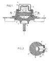
- This support is in the general form of a sealed revolution box around an X axis and comprising, in a manner known per se: an annular frame 1 extended radially by two perforated lugs 2 which can be joined together, in particular by bolting, with the support member, a rigid body 3 here being in the form of a bolt, the threaded portion of which extends downwards, a bolt which can be secured to the supported member, a thick, sealed frustoconical wall 4 of elastomeric material adhered respectively to the frame 1 and to the body 3 and capable of resisting elastically to axial compression and to transverse bending, - And a flexible waterproof membrane 5, the periphery of which is tightly fixed on the annular reinforcement 1.
- a watertight partition 6 divides the interior of the housing into two chambers A and B both filled with liquid, namely a chamber A, for work, arranged on the side of the wall 4 and a chamber B, for compensation, arranged on the side of the membrane 5.
- the partition 6 is constituted by a cylindrical wafer made of elastomer material hollowed out in its central zone by a cylindrical nozzle 19.
- the generatrices of the cylinder defining this nozzle are parallel to the axis X of the support and its cross section has a variable elongated shape comprised between an ellipse (shown in solid lines in FIG. 2) and a bean (mixed lines).
- one of the elongated faces defining the nozzle defines a thinned elastomer wall 20 forming part of the wafer 6.
- a pocket 21 is hollowed out in this wafer so as to form this thinned wall 20.
- This member C passes through openings 23 laterally recessed in the support without affecting the tightness of the two chambers filled with liquid from this support.
- the cross section of the nozzle 19 and therefore the resonant frequency F corresponding to the mass of liquid contained in this nozzle is varied.
- the intermediate partition here designated by the reference 61, is rigid and it is hollowed out axially by a passage 24 of relatively large section.
- This passage is crossed transversely by a section of elastic hose 25, one end of which is closed in leaktight manner by a bearing forming part of the partition 61 and the other end of which is connected in leaktight manner to an external source of a fluid capable of '' be subject to adjustable pressure.
- This section S is all the greater as said pressure is lower and vice versa: in FIG. 6, the profile in phantom 251 of the inflated hose corresponds to a small section S of the nozzle and, on the contrary, the profile in broken lines 252 of the deflated hose corresponds to a large section S.
- the frequency F of the beats to be checked is also linked to said section S.
- Hose 25 is advantageously chosen so such that its deformations as a function of the inflation pressure are oriented perpendicular to the direction of flow of the liquid in the nozzle.
- this hose 25 can be made to communicate in turn with an external source of pressurized fluid and with a pipe for discharging this fluid or for returning said fluid to the source.
- the external source can also be a source of vacuum or "vacuum”.
- the adjustment of the nozzle section can be controlled by the frequency of the oscillations to be damped.
- the above frequency detection is advantageously ensured by detecting the speed of rotation of the motor shaft using a tachometer or appropriate tachometer.
- a tachometer or appropriate tachometer it could also be provided indirectly, by being based on the variations of a parameter linked to said speed such as for example the vacuum prevailing in the intake manifold of the engine.
- hydraulic anti-vibration support capable of being adapted to damping oscillations of different frequencies, even during operation, so as to hold account for instantaneous real needs.
Landscapes
- Engineering & Computer Science (AREA)
- General Engineering & Computer Science (AREA)
- Mechanical Engineering (AREA)
- Combined Devices Of Dampers And Springs (AREA)
Abstract
Il s'agit d'un support antivibratoire hydraulique interposé entre un châssis et un moteur de véhicule, comportant une chambre de travail A et une chambre de compensation B remplies de liquide et réunies entre elles par un ajutage (19) dont la section, qui détermine la fréquence des oscillations les mieux amorties, peut être modifiée même lors du fonctionnement du support. Cet ajutage est délimité au moins en partie par une paroi déformable (20) et les modifications de la section dudit ajutage sont obtenues en déformant ladite paroi.It is a hydraulic anti-vibration support interposed between a chassis and a vehicle engine, comprising a working chamber A and a compensation chamber B filled with liquid and joined together by a nozzle (19) whose section, which determines the frequency of the best damped oscillations, can be modified even during the operation of the support. This nozzle is delimited at least in part by a deformable wall (20) and the modifications of the section of said nozzle are obtained by deforming said wall.
Description
L'invention concerne les dispositifs antivibratoires destinés à être interposés aux fins de support et d'amortissement entre deux éléments rigides individuellement soumis à certaines oscillations ou vibrations, éléments tels que par exemple un châssis de véhicule et le moteur de ce véhicule, l'amortissement faisant intervenir le battement d'une masse de liquide à travers un passage étranglé appelé ci-après "ajutage", à une fréquence de résonance qui est fonction des dimensions dudit ajutage et en particulier du rapport entre sa longueur axiale et sa section droite.The invention relates to anti-vibration devices intended to be interposed for the purposes of support and damping between two rigid elements individually subjected to certain oscillations or vibrations, elements such as for example a vehicle chassis and the engine of this vehicle, damping involving the beating of a mass of liquid through a throttled passage hereinafter called "nozzle", at a resonant frequency which is a function of the dimensions of said nozzle and in particular of the ratio between its axial length and its cross section.
L'invention concerne plus particulièrement, parmi les supports du genre en question, ceux qui sont constitués par un boîtier étanche interposé entre les deux éléments rigides, boîtier comportant une embase rigide solidarisable avec l'un des éléments rigides, un anneau rigide solidarisable avec l'autre élément rigide, une paroi annulaire élastique de support offrant une bonne résistance à la compression axiale et reliant de manière étanche l'embase rigide à l'anneau rigide et une membrane flexible raccordée de manière étanche à l'anneau rigide, l'intérieur du boîtier étant divisé par une cloison de séparation en deux chambres, savoir une chambre de travail située du côté de la paroi élastique et une chambre de compensation située du côté de la membrane flexible, ces deux chambres communiquant entre elles en permanence par l'ajutage, lequel est généralement aménagé dans la cloison de séparation ou autour de cette cloison, et étant remplies de liquide ainsi que cet ajutage.The invention relates more particularly, among the supports of the kind in question, those which consist of a sealed housing interposed between the two rigid elements, housing comprising a rigid base which can be joined to one of the rigid elements, a rigid ring which can be joined to the other rigid element, an elastic annular support wall offering good resistance to axial compression and sealingly connecting the rigid base to the rigid ring and a flexible membrane tightly connected to the rigid ring, the interior of the housing being divided by a partition into two chambers, namely a working chamber situated on the side of the elastic wall and a compensation chamber situated on the side of the flexible membrane, these two chambers communicating with each other permanently by the nozzle , which is generally arranged in the partition wall or around this partition, and being filled with liquid as well as this nozzle.
Dans les réalisations connues, le rapport entre la longueur et le diamètre moyen de l'ajutage, compris entre 2 et 100, est généralement déterminé une fois pour toutes en fonction de la fréquence F des oscillations que l'on désire amortir au maximum.In known embodiments, the ratio between the length and the average diameter of the nozzle, between 2 and 100, is generally determined once for all according to the frequency F of the oscillations which one wishes to dampen to the maximum.
Une telle formule présente l'inconvénient que ladite fréquence F est unique : en d'autres termes, s'il s'agit d'amortir les vibrations d'un moteur dont la fréquence varie de 50 à 200 Hz en fonction du régime de fonctionnement de ce moteur, les supports considérés n'assurent un bon amortissement que pour l'une F des valeurs de cette gamme de fréquences et pour les valeurs voisines de F, mais pas pour les autres valeurs.Such a formula has the disadvantage that said frequency F is unique: in other words, if it is a question of damping the vibrations of an engine whose frequency varies from 50 to 200 Hz depending on the operating regime of this motor, the supports considered only provide good damping for one of the values of this frequency range and for the values close to F, but not for the other values.
Pour remédier à cet inconvénient, il a déjà été proposé de modifier, au cours même du fonctionnement du support, le rapport entre la longueur et la section de l'ajutage de façon à rapprocher la fréquence d'accord F correspondant à l'amortissement maximum dudit support de la fréquence réelle G des oscillations principales à amortir.To remedy this drawback, it has already been proposed to modify, during the very operation of the support, the ratio between the length and the section of the nozzle so as to approximate the tuning frequency F corresponding to the maximum damping of said support of the real frequency G of the main oscillations to be damped.
Il a même été proposé de rendre automatiquement ces deux fréquences F et G égales à chaque instant en prévoyant des moyens pour détecter la fréquence des oscillations réelles imposées au support et des moyens pour modifier automatiquement le rapport longueur/section ci-dessus en fonction du résultat de cette détection.It has even been proposed to automatically make these two frequencies F and G equal at each instant by providing means for detecting the frequency of the actual oscillations imposed on the support and means for automatically modifying the length / section ratio above as a function of the result. of this detection.
C'est à ces supports réglables au cours même de leur fonctionnement, c'est-à-dire après leur mise en place entre l'élément rigide porteur et l'élément rigide porté, que la présente invention se rapporte, aussi bien dans le cas où le réglage considéré est assuré automatiquement que dans le cas où il est assuré manuellement.It is to these adjustable supports during their very operation, that is to say after their installation between the rigid carrying element and the rigid carried element, that the present invention relates, both in when the considered setting is ensured automatically only when it is ensured manually.
Dans les modes de réalisation connus de ces supports réglables, le rapport longueur/section de l'ajutage est modifié en obturant plus ou moins un tronçon de ce passage formant un siège annulaire rigide par un clapet rigide déplacé axialement en regard dudit siège.In the known embodiments of these adjustable supports, the length / section ratio of the nozzle is modified by closing more or less a section of this passage forming a rigid annular seat by a rigid valve displaced axially opposite said seat.
Les expériences conduites avec ces réalisations à clapet rigide n'ont pas donné satisfaction pour des raisons qui ne sont pas totalement élucidées et parmi lesquelles on peut citer la difficulté de positionner avec précision le clapet rigide vibrant par une chaîne d'organes cinématiques soumise elle-même aux vibrations.Experiments carried out with these achievements rigid valve have not been satisfactory for reasons which are not fully understood and among which we can cite the difficulty of precisely positioning the rigid valve vibrating by a chain of kinematic members itself subjected to vibration.
L'invention a pour but, surtout, de supprimer ces inconvénients.The object of the invention is, above all, to eliminate these drawbacks.
A cet effet les supports anti-vibratoires hydrauliques du genre considéré sont essentiellement caractérisés selon l'invention en ce que l'ajutage est délimité au moins en partie par une paroi déformable et en ce que les moyens pour modifier le rapport longueur/section dudit ajutage sont agencés de façon à déformer ladite paroi.To this end the hydraulic anti-vibration supports of the type considered are essentially characterized according to the invention in that the nozzle is delimited at least in part by a deformable wall and in that the means for modifying the length / section ratio of said nozzle are arranged to deform said wall.
Dans des modes de réalisation avantageux, on a recours en outre à l'une et/ou à l'autre des dispositions suivantes :
- la paroi déformable est constituée par un morceau de la cloison de séparation, alors formée en matériau élastomère, et les moyens de réglage comportent un tirant rigide reliant un point de cette paroi à un organe de commande extérieur au support,
- la paroi déformable fait partie d'une poche étanche et les moyens de réglage sont agencés de façon à relier cette poche à une source de fluide soumis à une pression ou dépression réglable, source extérieure au support,
- dans un support selon l'alinéa précédent, la poche est un tronçon de boyau flexible étanche qui s'étend au travers d'un passage évidé dans la cloison de séparation.In advantageous embodiments, use is also made of one and / or the other of the following arrangements:
the deformable wall is constituted by a piece of the partition, then formed from elastomeric material, and the adjustment means comprise a rigid tie rod connecting a point of this wall to a control member external to the support,
the deformable wall is part of a sealed pocket and the adjustment means are arranged so as to connect this pocket to a source of fluid subjected to adjustable pressure or depression, source external to the support,
- In a support according to the preceding paragraph, the pocket is a section of waterproof flexible hose which extends through a hollowed-out passage in the partition wall.
L'invention comprend, mises à part ces dispositions principales, certaines autres dispositions qui s'utilisent de préférence en même temps et dont il sera plus explicitement question ci-après.The invention includes, apart from these main provisions, certain other provisions which are preferably used at the same time and which will be more explicitly discussed below.
Dans ce qui suit, l'on va décrire quelques modes de réalisation de l'invention en se référant aux dessins ci-annexés d'une manière bien entendu non limitative.
- Les figure 1 et 2, de ces dessins, montrent respectivement en coupe axiale et en coupe transversale partielle selon II-II, figure 1, un support antivibratoire hydraulique établi conformément à l'invention.
- Les figures 3 à 5 montrent respectivement en coupe transversale selon III-III, figure 4 et en coupes axiales selon IV-IV et V-V, figure 3 une portion d'une variante d'un tel support également conforme à l'invention.
- La figure 6 est un schéma permettant d'expliquer le fonctionnement de ce dernier support.
- Figures 1 and 2 of these drawings show respectively in axial section and in partial cross section along II-II, Figure 1, a hydraulic anti-vibration support established in accordance with the invention.
- Figures 3 to 5 show respectively in cross section along III-III, Figure 4 and in axial sections along IV-IV and VV, Figure 3 a portion of a variant of such a support also according to the invention.
- Figure 6 is a diagram for explaining the operation of the latter support.
Dans chaque cas, le support considéré est destiné à être interposé entre un organe porteur rigide tel qu'un châssis de véhicule et un organe supporté rigide tel qu'un moteur à combustion interne.In each case, the support considered is intended to be interposed between a rigid support member such as a vehicle chassis and a rigid supported member such as an internal combustion engine.
Ce support se présente sous la forme générale d'un boîtier étanche de révolution autour d'un axe X et comportant, d'une façon connue en soi :
- une armature annulaire 1 prolongée radialement par deux pattes perforées 2 solidarisables, notamment par boulonnage, avec l'organe porteur,
- un corps rigide 3 se présentant ici sous la forme d'un boulon dont la portion filetée s'étend vers le bas, boulon solidarisable avec l'organe supporté,
- une paroi tronconique épaisse et étanche 4 en matériau élastomère adhérée respectivement sur l'armature 1 et sur le corps 3 et propre à résister élastiquement à la compression axiale et à la flexion transversale,
- et une membrane flexible étanche 5 dont le pourtour est fixé de façon étanche sur l'armature annulaire 1.This support is in the general form of a sealed revolution box around an X axis and comprising, in a manner known per se:
an annular frame 1 extended radially by two
a
a thick, sealed frustoconical wall 4 of elastomeric material adhered respectively to the frame 1 and to the
- And a flexible
Une cloison étanche 6 divise l'intérieur du boîtier en deux chambres A et B toutes les deux remplies de liquide, savoir une chambre A, de travail, disposée du côté de la paroi 4 et une chambre B, de compensation, disposée du côté de la membrane 5.A watertight partition 6 divides the interior of the housing into two chambers A and B both filled with liquid, namely a chamber A, for work, arranged on the side of the wall 4 and a chamber B, for compensation, arranged on the side of the
Un capot de protection métallique 17, dont le bord est fixé sur l'armature annulaire 1, entoure la membrane 5.A metal
Dans le mode de réalisation schématisé sur les figures 1 et 2, la cloison 6 est constituée par une galette cylindrique en matériau élastomère évidée dans sa zone centrale par un ajutage cylindrique 19.In the embodiment shown diagrammatically in FIGS. 1 and 2, the partition 6 is constituted by a cylindrical wafer made of elastomer material hollowed out in its central zone by a
Les génératrices du cylindre définissant cet ajutage sont parallèles à l'axe X du support et sa section droite présente une forme allongée variable comprise entre une ellipse (représentée en traits pleins sur la figure 2) et un haricot (traits mixtes).The generatrices of the cylinder defining this nozzle are parallel to the axis X of the support and its cross section has a variable elongated shape comprised between an ellipse (shown in solid lines in FIG. 2) and a bean (mixed lines).
A cet effet l'une des faces allongées définissant l'ajutage délimite une paroi amincie 20 en élastomère faisant partie de la galette 6.To this end, one of the elongated faces defining the nozzle defines a
En d'autres termes, une poche 21 est évidée dans cette galette de façon à former cette paroi amincie 20.In other words, a
A l'intérieur de cette poche est logé un tirant rigide 22 dont une extrémité élargie est adhérée à la paroi 20 et dont l'autre extrémité est reliée à un organe de commande extérieur tel qu'un câble sous gaine de type Bowden, organe schématisé par le symbole C.Inside this pocket is housed a
Cet organe C traverse des lumières 23 évidées latéralement dans le support sans nuire à l'étanchéité des deux chambres remplies de liquide de ce support.This member C passes through
En agissant sur l'organe C, on fait varier la section droite de l'ajutage 19 et donc la fréquence F de résonance correspondant à la masse de liquide contenue dans cet ajutage.By acting on the member C, the cross section of the
Or, comme indiqué précédemment, parmi les vibrations ou oscillations imposées au support, ce sont précisément celles dont la fréquence est égale à ladite valeur F qui sont amorties ou filtrées au maximum par ledit support, puisque ce sont celles-là qui provoquent la résonance de la masse liquide considérée, présente dans l'ajutage.However, as indicated above, among the vibrations or oscillations imposed on the support, it is precisely those whose frequency is equal to said value F which are damped or filtered as much as possible by said support, since these are the ones which cause the resonance of the liquid mass considered, present in the nozzle.
On dispose ainsi d'un moyen extrêmement simple et souple pour modifier ladite fréquence F en fonction des besoins.There is thus an extremely simple and flexible means for modifying said frequency F as required.
Dans la variante des figures 3 à 6, la cloison intermédiaire, ici désignée par la référence 6₁, est rigide et elle est évidée axialement par un passage 24 de relativement grande section.In the variant of FIGS. 3 to 6, the intermediate partition, here designated by the
Ce passage est barré transversalement par un tronçon de boyau élastique 25 dont une extrémité est obturée de façon étanche par une portée faisant partie de la cloison 6₁ et dont l'autre extrémité est reliée de façon étanche à une source extérieure d'un fluide susceptible d'être soumis à une pression réglable.This passage is crossed transversely by a section of
Cette liaison est ici effectuée par l'intermédiaire :
- d'une chambre annulaire 26 évidée à l'intérieur de la cloison 6₁,
- et de lumières latérales 23 évidées dans le support comme pour le précédent mode de réalisation.This connection is made here through:
an
- And
En agissant sur l'organe extérieur --schématisé par le symbole D-- de réglage de la pression du fluide contenu dans le boyau 25, on modifie le degré de gonflement de ce boyau, et donc la section résiduelle S de l'ajutage ou passage étranglé reliant les deux chambres du support, ledit ajutage étant formé par la portion, du passage 24, non occupée par le boyau 25.By acting on the external member - schematized by the symbol D - for adjusting the pressure of the fluid contained in the
Cette section S est d'autant plus grande que ladite pression est plus basse et inversement : sur la figure 6, le profil en traits mixtes 25₁ du boyau gonflé correspond à une petite section S de l'ajutage et, au contraire, le profil en traits interrompus 25₂ du boyau dégonflé correspond à une grande section S.This section S is all the greater as said pressure is lower and vice versa: in FIG. 6, the profile in
Comme précédemment, la fréquence F des battements à contrôler est encore liée à ladite section S.As before, the frequency F of the beats to be checked is also linked to said section S.
Le boyau 25 est avantageusement choisi de façon telle que ses déformations en fonction de la pression du gonflage soient orientées perpendiculairement à la direction d'écoulement du liquide dans l'ajutage.
Pour régler le degré de gonflage du boyau 25, on peut faire communiquer à tour de rôle ce boyau 25 avec une source extérieure de fluide sous pression et avec une conduite d'évacuation de ce fluide ou de retour dudit fluide à la source. La source extérieure peut également être une source de dépression ou de "vide".To adjust the degree of inflation of the
Dans chaque cas, on peut asservir le réglage de la section de l'ajutage à la fréquence des oscillations à amortir.In each case, the adjustment of the nozzle section can be controlled by the frequency of the oscillations to be damped.
A cet effet, l'on peut prévoir des moyens pour détecter à chaque instant la fréquence réelle des oscillations imposées au support et asservir les moyens de réglage à la valeur ainsi détectée pour cette fréquence réelle.To this end, it is possible to provide means for detecting at all times the real frequency of the oscillations imposed on the support and for controlling the adjustment means to the value thus detected for this real frequency.
Dans les modes de réalisation pour lesquels le support est destiné à amortir les vibrations d'un moteur, la détection de fréquence ci-dessus est avantageusement assurée en détectant la vitesse de rotation de l'arbre moteur à l'aide d'un tachymètre ou compte-tour approprié. Mais elle pourrait également être assurée de façon indirecte, en étant basée sur les variations d'un paramètre lié à ladite vitesse tel que par exemple la dépression régnant dans la tubulure d'admission du moteur.In the embodiments for which the support is intended to dampen the vibrations of a motor, the above frequency detection is advantageously ensured by detecting the speed of rotation of the motor shaft using a tachometer or appropriate tachometer. However, it could also be provided indirectly, by being based on the variations of a parameter linked to said speed such as for example the vacuum prevailing in the intake manifold of the engine.
En suite de quoi, et quel que soit le mode de réalisation adopté, on dispose finalement d'un support antivibratoire hydraulique susceptible d'être adapté à l'amortissement d'oscillations de fréquences différentes, même en cours de fonctionnement, de façon à tenir compte des besoins réels instantanés.Following this, and whatever the embodiment adopted, there is finally a hydraulic anti-vibration support capable of being adapted to damping oscillations of different frequencies, even during operation, so as to hold account for instantaneous real needs.
Comme il va de soi, et comme il résulte d'ailleurs déjà de ce qui précède, l'invention ne se limite nullement à ceux de ses modes d'application et de réalisation qui ont été plus spécialement envisagés ; elle en embrasse, au contraire, toutes les variantes.As it goes without saying, and as already follows from the above, the invention is not limited in no way to those of its modes of application and embodiments which have been more especially envisaged; on the contrary, it embraces all its variants.
Claims (4)
Applications Claiming Priority (2)
| Application Number | Priority Date | Filing Date | Title |
|---|---|---|---|
| FR8604929A FR2596837B1 (en) | 1986-04-07 | 1986-04-07 | IMPROVEMENTS TO HYDRAULIC ANTI-VIBRATION SUPPORTS |
| FR8604929 | 1986-04-07 |
Publications (2)
| Publication Number | Publication Date |
|---|---|
| EP0241353A1 true EP0241353A1 (en) | 1987-10-14 |
| EP0241353B1 EP0241353B1 (en) | 1989-10-04 |
Family
ID=9333964
Family Applications (1)
| Application Number | Title | Priority Date | Filing Date |
|---|---|---|---|
| EP87400708A Expired EP0241353B1 (en) | 1986-04-07 | 1987-03-31 | Modifications of antivibration mountings of the hydraulic type |
Country Status (4)
| Country | Link |
|---|---|
| US (1) | US4768759A (en) |
| EP (1) | EP0241353B1 (en) |
| DE (1) | DE3760686D1 (en) |
| FR (1) | FR2596837B1 (en) |
Cited By (3)
| Publication number | Priority date | Publication date | Assignee | Title |
|---|---|---|---|---|
| EP0380760A1 (en) * | 1989-02-03 | 1990-08-08 | Firma Carl Freudenberg | Elastomeric mounting |
| US6050554A (en) * | 1996-09-24 | 2000-04-18 | Draftex Industries Limited | Vibration damping assemblies |
| GB2342977A (en) * | 1998-10-23 | 2000-04-26 | Draftex Ind Ltd | Hydroelastic engine mount |
Families Citing this family (10)
| Publication number | Priority date | Publication date | Assignee | Title |
|---|---|---|---|---|
| DE3805761A1 (en) * | 1988-02-24 | 1989-09-07 | Daimler Benz Ag | HYDRAULIC DAMPING RUBBER BEARING |
| US5067684A (en) * | 1988-12-22 | 1991-11-26 | Moog Inc. | Vibration-isolating machine mount |
| JPH0520997A (en) * | 1991-07-11 | 1993-01-29 | Fuji Electric Co Ltd | Circuit breaker |
| JPH05223139A (en) * | 1991-12-20 | 1993-08-31 | Bridgestone Corp | Vibration control device |
| US5704596A (en) * | 1993-08-18 | 1998-01-06 | Bell Helicopter | Vibration isolation system |
| US5435531A (en) * | 1993-08-18 | 1995-07-25 | Bell Helicopter Textron Inc. | Vibration isolation system |
| FR2710957B1 (en) * | 1993-10-05 | 1995-12-08 | Hutchinson | Improvements to hydraulic anti-vibration supports. |
| US6619611B2 (en) * | 2001-07-02 | 2003-09-16 | Newport Corporation | Pneumatic vibration isolator utilizing an elastomeric element for isolation and attenuation of horizontal vibration |
| JP4135719B2 (en) * | 2004-08-31 | 2008-08-20 | 東海ゴム工業株式会社 | Engine mount |
| US10361606B2 (en) * | 2014-03-12 | 2019-07-23 | Hutchinson | Hydraulic anti-vibration device provided with an electricity generator device and electricity generator device for such an anti-vibration device |
Citations (4)
| Publication number | Priority date | Publication date | Assignee | Title |
|---|---|---|---|---|
| DE2428326A1 (en) * | 1974-06-12 | 1976-01-02 | Dornier System Gmbh | Vibration damper with temperature compensation - has throttle chamber whose cross-section varies due to expansion/contraction of a liquid |
| DE3340152A1 (en) * | 1983-02-04 | 1984-08-16 | Toyota Jidosha K.K., Toyota, Aichi | FASTENING ARRANGEMENT FOR A MOTOR GEARBOX |
| DE3316025A1 (en) * | 1983-05-03 | 1984-11-08 | Tillmann 6108 Weiterstadt Freudenberg | Engine mount |
| EP0155646A2 (en) * | 1984-03-23 | 1985-09-25 | METZELER Gesellschaft mit beschränkter Haftung | Hydraulic motor support with two damping spaces |
Family Cites Families (15)
| Publication number | Priority date | Publication date | Assignee | Title |
|---|---|---|---|---|
| US2318437A (en) * | 1942-03-28 | 1943-05-04 | Carroll B Vickers | Shock absorber |
| US2457749A (en) * | 1944-05-06 | 1948-12-28 | Gen Tire & Rubber Co | Energy dissipating antivibration device |
| EP0006819B1 (en) * | 1978-07-03 | 1984-06-27 | Automobiles Peugeot | Suspension device in particular for a vehicle engine |
| US4312493A (en) * | 1979-05-05 | 1982-01-26 | Stauffer Rita A | Apparatus for controlled liquid administration |
| AU523318B2 (en) * | 1980-06-23 | 1982-07-22 | Bridgestone Tire Co. Ltd. | Rubber vibration isolators |
| DE3027742A1 (en) * | 1980-07-22 | 1982-02-04 | Metzeler Kautschuk GmbH, 8000 München | TWO-CHAMBER ENGINE MOUNT WITH HYDRAULIC DAMPING |
| DE3048888C2 (en) * | 1980-12-23 | 1982-11-04 | Audi Nsu Auto Union Ag, 7107 Neckarsulm | Device for the elastic mounting of machines or machine parts, for example an internal combustion engine in a motor vehicle |
| JPS5854248A (en) * | 1981-09-25 | 1983-03-31 | Toyota Motor Corp | Vibro-isolating rubber device |
| JPS5965635A (en) * | 1982-10-06 | 1984-04-13 | Toyota Motor Corp | Vibrationproof rubber device |
| GB2135795B (en) * | 1983-02-09 | 1987-12-16 | Mitsubishi Motors Corp | A rolling control apparatus for an engine |
| US4635897A (en) * | 1983-09-30 | 1987-01-13 | Airsonics License Partnership | Tube flow shut-off device |
| JPS60116937A (en) * | 1983-11-28 | 1985-06-24 | Toyota Motor Corp | Vibration-proof supporting method of internal- combustion engine for car |
| JPS60192195A (en) * | 1984-03-13 | 1985-09-30 | 日産自動車株式会社 | Device for mounting power unit |
| JPS60234143A (en) * | 1984-05-03 | 1985-11-20 | Toyoda Gosei Co Ltd | Liquid encapsulated vibro-preventive device |
| US4641808A (en) * | 1985-02-22 | 1987-02-10 | Flower Wallace C | Dynamic vibration attenuator utilizing inertial fluid |
-
1986
- 1986-04-07 FR FR8604929A patent/FR2596837B1/en not_active Expired - Fee Related
-
1987
- 1987-03-31 DE DE8787400708T patent/DE3760686D1/en not_active Expired
- 1987-03-31 EP EP87400708A patent/EP0241353B1/en not_active Expired
- 1987-04-02 US US07/033,189 patent/US4768759A/en not_active Expired - Fee Related
Patent Citations (4)
| Publication number | Priority date | Publication date | Assignee | Title |
|---|---|---|---|---|
| DE2428326A1 (en) * | 1974-06-12 | 1976-01-02 | Dornier System Gmbh | Vibration damper with temperature compensation - has throttle chamber whose cross-section varies due to expansion/contraction of a liquid |
| DE3340152A1 (en) * | 1983-02-04 | 1984-08-16 | Toyota Jidosha K.K., Toyota, Aichi | FASTENING ARRANGEMENT FOR A MOTOR GEARBOX |
| DE3316025A1 (en) * | 1983-05-03 | 1984-11-08 | Tillmann 6108 Weiterstadt Freudenberg | Engine mount |
| EP0155646A2 (en) * | 1984-03-23 | 1985-09-25 | METZELER Gesellschaft mit beschränkter Haftung | Hydraulic motor support with two damping spaces |
Non-Patent Citations (1)
| Title |
|---|
| PATENT ABSTRACTS OF JAPAN, vol. 10, no. 100 (M-470)[2157], 16th April 1986; & JP-A-60 234 143 (TOYODA GOSEI K.K.) 20-11-1985 * |
Cited By (3)
| Publication number | Priority date | Publication date | Assignee | Title |
|---|---|---|---|---|
| EP0380760A1 (en) * | 1989-02-03 | 1990-08-08 | Firma Carl Freudenberg | Elastomeric mounting |
| US6050554A (en) * | 1996-09-24 | 2000-04-18 | Draftex Industries Limited | Vibration damping assemblies |
| GB2342977A (en) * | 1998-10-23 | 2000-04-26 | Draftex Ind Ltd | Hydroelastic engine mount |
Also Published As
| Publication number | Publication date |
|---|---|
| FR2596837B1 (en) | 1990-06-22 |
| FR2596837A1 (en) | 1987-10-09 |
| DE3760686D1 (en) | 1989-11-09 |
| US4768759A (en) | 1988-09-06 |
| EP0241353B1 (en) | 1989-10-04 |
Similar Documents
| Publication | Publication Date | Title |
|---|---|---|
| EP0275503B1 (en) | Damper with load compensation | |
| EP0304599B1 (en) | Hydraulic shock absorber equipped with means for varying the damping characteristics | |
| EP0241353A1 (en) | Modifications of antivibration mountings of the hydraulic type | |
| FR2573365A1 (en) | SUSPENSION FOR VEHICLE | |
| EP0388293B1 (en) | Drive belt tensioning device | |
| FR2635364A1 (en) | ADJUSTABLE HYDRAULIC VIBRATION DAMPER FOR A MOTOR VEHICLE | |
| FR2663706A1 (en) | Elastic mount filled with a fluid and including means for controlling the elastic deformation of one or more diaphragms defining one or more equilibrium chambers | |
| EP0223712B1 (en) | Modifications of hydraulic dampers | |
| FR2627565A1 (en) | RUBBER SUPPORT WITH HYDRAULIC DAMPING EFFECT | |
| FR2496810A1 (en) | DEVICE FOR THE ELASTIC MOUNTING OF MACHINES AND PARTS OF MACHINES, FOR EXAMPLE OF AN INTERNAL COMBUSTION ENGINE IN A MOTOR VEHICLE | |
| FR2627564A1 (en) | RUBBER SUPPORT WITH HYDRAULIC DAMPING | |
| EP0297974B1 (en) | Hydraulic damping mounts | |
| EP0278824B1 (en) | Hydraulic antivibration mountings | |
| EP0117203B1 (en) | Sealing device for a hydraulic energy damper of the telescopic type | |
| FR2463040A1 (en) | HYDRAULIC STEERING IN CREMAILLERE | |
| FR2657117A1 (en) | Device with a camshaft and method for manufacturing it | |
| FR2795148A1 (en) | Damper for combustion engine or car's body contains two parts linked by elastic component and force applying chamber to be connected to vacuum source or atmospheric air by switching valve | |
| FR2771790A1 (en) | TORQUE CONVERTER | |
| EP0300858A1 (en) | Rotary tensioning device for a belt drive | |
| FR2778701A1 (en) | Radial piston pump of camshaft and cylinders for vehicle media | |
| FR2687099A1 (en) | BEARING FOR OSCILLATING WHEEL GUIDING ARM. | |
| EP1167159B1 (en) | Servo valve for hydraulic power steering of a motor vehicle | |
| FR2619420A1 (en) | PUMP OR VANE MOTOR | |
| EP0490719A1 (en) | Hydrolastic suspension device | |
| FR2573701A1 (en) | Pneumatic suspension with variable characteristics |
Legal Events
| Date | Code | Title | Description |
|---|---|---|---|
| PUAI | Public reference made under article 153(3) epc to a published international application that has entered the european phase |
Free format text: ORIGINAL CODE: 0009012 |
|
| AK | Designated contracting states |
Kind code of ref document: A1 Designated state(s): CH DE ES FR GB IT LI NL SE |
|
| 17P | Request for examination filed |
Effective date: 19870930 |
|
| 17Q | First examination report despatched |
Effective date: 19880811 |
|
| GRAA | (expected) grant |
Free format text: ORIGINAL CODE: 0009210 |
|
| ITF | It: translation for a ep patent filed | ||
| AK | Designated contracting states |
Kind code of ref document: B1 Designated state(s): CH DE ES FR GB IT LI NL SE |
|
| PG25 | Lapsed in a contracting state [announced via postgrant information from national office to epo] |
Ref country code: SE Effective date: 19891004 Ref country code: NL Effective date: 19891004 |
|
| REF | Corresponds to: |
Ref document number: 3760686 Country of ref document: DE Date of ref document: 19891109 |
|
| GBT | Gb: translation of ep patent filed (gb section 77(6)(a)/1977) | ||
| PG25 | Lapsed in a contracting state [announced via postgrant information from national office to epo] |
Ref country code: ES Free format text: LAPSE BECAUSE OF FAILURE TO SUBMIT A TRANSLATION OF THE DESCRIPTION OR TO PAY THE FEE WITHIN THE PRESCRIBED TIME-LIMIT Effective date: 19900115 |
|
| NLV1 | Nl: lapsed or annulled due to failure to fulfill the requirements of art. 29p and 29m of the patents act | ||
| PG25 | Lapsed in a contracting state [announced via postgrant information from national office to epo] |
Ref country code: LI Effective date: 19900331 Ref country code: CH Effective date: 19900331 |
|
| PLBE | No opposition filed within time limit |
Free format text: ORIGINAL CODE: 0009261 |
|
| STAA | Information on the status of an ep patent application or granted ep patent |
Free format text: STATUS: NO OPPOSITION FILED WITHIN TIME LIMIT |
|
| 26N | No opposition filed | ||
| REG | Reference to a national code |
Ref country code: CH Ref legal event code: PL |
|
| ITTA | It: last paid annual fee | ||
| PGFP | Annual fee paid to national office [announced via postgrant information from national office to epo] |
Ref country code: FR Payment date: 19970313 Year of fee payment: 11 |
|
| PGFP | Annual fee paid to national office [announced via postgrant information from national office to epo] |
Ref country code: DE Payment date: 19970324 Year of fee payment: 11 |
|
| PGFP | Annual fee paid to national office [announced via postgrant information from national office to epo] |
Ref country code: GB Payment date: 19970325 Year of fee payment: 11 |
|
| PG25 | Lapsed in a contracting state [announced via postgrant information from national office to epo] |
Ref country code: GB Free format text: LAPSE BECAUSE OF NON-PAYMENT OF DUE FEES Effective date: 19980331 Ref country code: FR Free format text: THE PATENT HAS BEEN ANNULLED BY A DECISION OF A NATIONAL AUTHORITY Effective date: 19980331 |
|
| GBPC | Gb: european patent ceased through non-payment of renewal fee |
Effective date: 19980331 |
|
| PG25 | Lapsed in a contracting state [announced via postgrant information from national office to epo] |
Ref country code: DE Free format text: LAPSE BECAUSE OF NON-PAYMENT OF DUE FEES Effective date: 19981201 |
|
| REG | Reference to a national code |
Ref country code: FR Ref legal event code: ST |
|
| PG25 | Lapsed in a contracting state [announced via postgrant information from national office to epo] |
Ref country code: IT Free format text: LAPSE BECAUSE OF NON-PAYMENT OF DUE FEES;WARNING: LAPSES OF ITALIAN PATENTS WITH EFFECTIVE DATE BEFORE 2007 MAY HAVE OCCURRED AT ANY TIME BEFORE 2007. THE CORRECT EFFECTIVE DATE MAY BE DIFFERENT FROM THE ONE RECORDED. Effective date: 20050331 |