EP0304599B1 - Mit Mitteln zur Änderung der Dämpfungscharakteristik ausgerüsteter hydraulischer Stossdämpfer - Google Patents
Mit Mitteln zur Änderung der Dämpfungscharakteristik ausgerüsteter hydraulischer Stossdämpfer Download PDFInfo
- Publication number
- EP0304599B1 EP0304599B1 EP88111197A EP88111197A EP0304599B1 EP 0304599 B1 EP0304599 B1 EP 0304599B1 EP 88111197 A EP88111197 A EP 88111197A EP 88111197 A EP88111197 A EP 88111197A EP 0304599 B1 EP0304599 B1 EP 0304599B1
- Authority
- EP
- European Patent Office
- Prior art keywords
- shock absorber
- chamber
- pressure
- valve
- control valve
- Prior art date
- Legal status (The legal status is an assumption and is not a legal conclusion. Google has not performed a legal analysis and makes no representation as to the accuracy of the status listed.)
- Expired - Lifetime
Links
Images
Classifications
-
- F—MECHANICAL ENGINEERING; LIGHTING; HEATING; WEAPONS; BLASTING
- F16—ENGINEERING ELEMENTS AND UNITS; GENERAL MEASURES FOR PRODUCING AND MAINTAINING EFFECTIVE FUNCTIONING OF MACHINES OR INSTALLATIONS; THERMAL INSULATION IN GENERAL
- F16F—SPRINGS; SHOCK-ABSORBERS; MEANS FOR DAMPING VIBRATION
- F16F9/00—Springs, vibration-dampers, shock-absorbers, or similarly-constructed movement-dampers using a fluid or the equivalent as damping medium
- F16F9/32—Details
- F16F9/44—Means on or in the damper for manual or non-automatic adjustment; such means combined with temperature correction
- F16F9/46—Means on or in the damper for manual or non-automatic adjustment; such means combined with temperature correction allowing control from a distance, i.e. location of means for control input being remote from site of valves, e.g. on damper external wall
- F16F9/466—Throttling control, i.e. regulation of flow passage geometry
Definitions
- the present invention relates to a hydraulic shock absorber intended to be mounted between the chassis or the body of a motor vehicle and an unsprung part, for example a vehicle wheel.
- the invention relates in particular to shock absorbers comprising a control valve mounted so as to be controlled to cause a reduction in the damping force from a certain compression speed of the rod of the shock absorber.
- dampers of this type already described for example in French patent application FR-A-2287627 (SIRVEN) which for this purpose comprise a control valve controlled by the pressure of the hydraulic fluid so as to put in communication, when it opens, the two chambers delimited in the cylinder of the shock absorber by the main piston actuated by the rod of the shock absorber.
- the control pressure of the control valve is obtained by braking the flow to a reservoir of the excess fluid due to the reduction in useful volume of the cylinder following the penetration of the piston rod in one of the cylinder chambers.
- the control valve can also be subjected to the action of a substantially constant reference pressure, one of the faces of the control valve then being able to constitute a surface portion delimiting a reference chamber filled with a reference fluid for example a gas at a determined pressure.
- This reference chamber can be closed and insulated either in the atmosphere or connected to the part of the fluid tank filled with gas so as to achieve a pressure balance.
- an elastic block for example made of elastomer, capable of varying the useful volume of the shock absorber during a movement of rapid compression of the rod thus modifying the operating characteristics during a sudden compression by acting on the opening of the control valve by increase in pressure inside the shock absorber.
- the restriction control means are located in the piston in the case of a single-tube shock absorber, which causes difficulties in locating these control means and controlling them from the outside.
- the means for controlling the restrictions intended to modify the characteristics of the compression damper can be arranged either in the piston or in the vicinity of a valve located at the end of the cylinder.
- the object of the present invention is to modify the shock absorbers of the type mentioned in the preamble, so as to allow their operating characteristics to be varied at will, in particular by taking into account different parameters related to the movement of the vehicle.
- the damper comprises a cylinder containing a hydraulic fluid, a piston actuated by a rod defining in the cylinder a first and a second chamber, said second chamber containing a rod, a fluid reservoir capable of communicating with the first chamber, a control valve subjected on the one hand to the pressure of the fluid in the first chamber tending to open the valve and to the action of a spring recall, and of the substantially constant pressure of a reference gas, tending to close the valve.
- a restriction is placed between the reservoir and the first chamber so as to allow only the passage of hydraulic fluid from the first chamber to the reservoir by defining a control pressure which causes the valve to open when the compression speed of the rod exceeds a specified limit value.
- the damper comprises means controlled to vary the flow rate capable of passing through the aforementioned restriction so as to cause the opening of the control valve at compression speeds different from the aforementioned determined limit value.
- the control valve may be subjected to the pressure of the fluid in the second chamber, tending to close it.
- the control valve can, in a variant, be subjected to the pressure of the fluid in an intermediate space communicating, during a compression movement, on the one hand through a very flexible valve with the second chamber and through the valve control with the first chamber and on the other hand, through a restriction, with the reservoir, said pressure tending to open the control valve.
- the controlled means may include an electric control motor, advantageously mounted on the vehicle body, outside the shock absorber.
- the pressure of the reference gas acting on the control valve can be the atmospheric pressure. It can also be a higher pressure, the reference chamber then preferably being in communication with the reservoir by a conduit, for example arranged outside the damper.
- the reservoir is preferably arranged at the upper part of the cylinder fixed to the body of the vehicle opposite the piston rod.
- the control valve is preferably mounted in the piston itself.
- the cylinder is fixed to the vehicle body by an elastic block capable of varying the internal volume of the cylinder, thus causing an opening of the control valve even before the displacement of the piston during a sudden compression movement.
- the cylinder comprises the control valve and is arranged inside a cylindrical envelope in communication with the fluid reservoir by a restriction.
- the envelope cylindrical is advantageously fixed to the vehicle body by means of an elastic block capable of varying the internal volume of the cylindrical casing, which causes, as before, the opening of the control valve during a movement of sudden compression even before any movement of the piston.
- control means which equip the restriction allowing the passage of the hydraulic fluid from the first chamber to the reservoir during a compression movement, it becomes possible in such a damper to modify the operating characteristics in compression. It will be noted that, unlike what happens in a conventional type damper, a reduction in the flow rate through this restriction results in a reduction in the damping force for the lower values of the compression speed of the piston rod being given that the reduction in the flow rate of passage towards the reservoir during compression results in a faster opening of the control valve.
- the control valve plays no role.
- the rebound damping force is conventionally defined by the restrictions mounted in the piston.
- the hydraulic fluid coming from the reservoir passes through a simple make-up valve which allows the passage of the fluid only from the tank towards the cylinder of the shock absorber, the make-up valve causing practically no significant pressure drop.
- shock absorbers of this type where an elastic block has been mounted between an element linked to the vehicle body and an element linked to the cylinder of the shock absorber in order to obtain an immediate opening of the control valve during a movement of sudden compression, one can consider modifying the operating characteristics of the shock absorber during an expansion movement.
- these shock absorbers there is in fact between the wheel and the vehicle body a connection comprising not only the shock absorber but also a spring element represented by the elastic block.
- this elastic block stretches under the action of the detent movement, which increases the useful volume of the first chamber of the shock absorber.
- the present invention therefore also has the object of modifying the rigidity of the elastic connection existing between the part of the shock absorber linked to the wheels of the vehicle and the body of the vehicle.
- a damper of the previously mentioned type in which the reference chamber is in communication with the tank subjected to a pressure greater than atmospheric pressure, in which an elastic block is mounted between the vehicle body and the shock absorber, that the first chamber is supplied with hydraulic fluid coming from the reservoir, during a rapid expansion movement of the piston rod, by a restriction closed by a non-return valve whose rigidity is such that it results in a reduction pressure in the first chamber capable of creating a hydraulic action on the elastic block opposing the deformation of said elastic block due to the rapid expansion movement.
- this non-return valve By an appropriate choice of the rigidity of this non-return valve, it is possible to ensure that the connection between the shock absorber and the vehicle body is substantially rigid as if the shock absorber were mounted on ball joints without elasticity and this , despite the existence of the elastic block which retains the function of reducing the damping force during an abrupt compression movement.
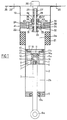
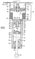
- the shock absorber of the invention comprises a piston 1 which slides inside a cylinder 2 and which delimits therein a first chamber 2 at the bottom side of the piston 1 and a second chamber 2 b which encloses the rod 3 made integral with the piston 1 for example by means of a threaded end 4.
- the cylinder 2 is secured at its lower end with a closure part 5 comprising a central bore provided with a sealing ring 5 a through which the rod 3 of the piston passes.
- the piston rod has a hooking ring 6 a which can be connected to the wheel of the motor vehicle.
- the piston is made in the form of a hollow part having a central core 7 provided with a thread receiving the threaded end 4 of the piston rod 3 is secured to the side walls of the piston 1 by ribs 8 leaving a free passage for hydraulic fluid.
- the central core 7 also has a housing acting as a reference chamber 9 delimited laterally by an annular wall 10 secured to the central core 7.
- the reference chamber 9 is filled with a reference fluid, for example a gas, the pressure of which is substantially constant taking into account the small variable volume of the chamber 9.
- the chamber 9 is limited at its upper part to be movable by the lower surface of a control valve 11 which is in the form of an auxiliary piston 11 a which can slide in sealed manner inside the chamber 9.
- control valve 11 has in fact a lower part 11 a which slides inside the chamber 9 and an upper plate 11 b of larger diameter, coming from its upper face in sealing contact with a seat secured to a washer 12 fixed to the side walls of the piston 1 by a clamping ring 13.
- the control valve 11 is urged in the direction of its closing against the seat of the washer 12 by the action of a spring 14 which bears on the one hand on a flange of the central core 7 of the piston 1 and of on the other hand on an annular cup 14 a surrounding the lower part 11 a of the control valve 11.
- the plate 11 b of the control valve 11 has perforations 15 cooperating with a non-return valve 16 held against the lower surface of the plate 11 b by the cup 15 and the spring 14 so as to allow the limited passage of the hydraulic fluid between the first chamber 2 a and the second bedroom 2 b .
- the washer 12 also has holes 17 cooperating with a non-return valve 18 held by clamping between the washer 12 and the clamping ring 13 so as to allow a limited passage of hydraulic fluid from the second chamber 2b to the first chamber 2 a .
- the upper part of the shock absorber is occupied by a hydraulic fluid reservoir 19 fixed directly to the body 20 of the vehicle.
- the cylinder 2 is surrounded at its upper part by an elastic elastomer block 21 which is integral with the external wall of the cylinder 2 and with the internal wall of a cylindrical sleeve 22 which continues upwards to form the reservoir 19 and has in its upper part a fixing flange on the body 20 of the motor vehicle by means of screws 23.
- a separation element 24 is fixed inside the sleeve 22 so as to separate the hydraulic fluid located in the tank 19 hydraulic fluid in the first chamber 2 a .
- the separation piece 24 has a central bore receiving a rotary shaft 25 which extends vertically upward through the reservoir 19 to the drive motor 26 mounted directly on the body 20 of the vehicle outside the damper.
- the passage of the shaft 25 in the reservoir 19 is done by means of a sealing and guide sleeve 27 provided with an appropriate seal 28.
- the shaft 25 after having passed through the separation piece 24 is mounted with clamping by means of a threaded ring 29 against an anti-friction washer 30 which facilitates the rotation of the shaft 25 relative to the fixed separation piece 24.
- the ring 29 also has a shoulder which allows the support of a helical spring 31 acting so as to close a valve 32 having holes 33. The valve 32 is held between the ring 29 and a washer 34.
- the valve 32 closes in its peripheral zone a plurality of passages axial 35 practiced in the separation piece 24.
- the rigidity of the valve 32 is chosen so that said valve has practically no braking effect on the fluid escaping through the passages 35 from the reservoir 19 to the first chamber 2 a during a detent movement of the piston 1.
- the role of the valve 32 is therefore essentially to prevent any flow of hydraulic fluid in the opposite direction, that is to say from the first chamber 2 a to the reservoir 19 during a compression movement of the piston 1.
- a ring 36 provided with two groups of perforations is mounted so as to be integral with the rotary shaft 25 and to be in contact by its lower front face with the upper front face of a passage piece 38 mounted fixed relative to the separation piece 24.
- the passage piece 38 comprises two passages 39 communicating on its upper front face with two oblong curvilinear grooves 40 which can be put in communication with the holes 37 of the ring 36 as a function of the rotation of the latter with the shaft 25.
- the passages 39 communicate with passages 41 passing through the separation piece 24.
- a non-return valve 42 is further mounted between the passage piece 38 and the separation piece 24 so as to allow the passage of the fluid from the first chamber 2 a up to reservoir 19 and prevent any passage of fluid in the opposite direction.
- An additional non-return valve 43 is mounted above the ring 36 and cooperates with a spring 44 so as to prevent, like the valve 42, any passage of hydraulic fluid from the reservoir 19 to the first chamber 2 a .
- the action of the motor 26 causing the rotation of the shaft 25 causes the rotation of the ring 36 so that a greater or lesser number of perforations 37 allow the passage of the fluid coming from the bores 39.
- the non-blocked passages laminate l oil passing from the lower part of the separation piece 24, that is to say from the first chamber 2 a of the damper.
- the non-return valve 42 is chosen to be relatively rigid in order to allow the passage of oil only from bottom to top and only for high oil flows. Under these conditions, the action of the non-return valve 42 is limited to high compression speeds and the pressure drop through this valve is greater than the opening pressure of the control valve 11.
- the p1 pressure in the first chamber 2 a increases depending on the compression speed V. It is the same difference between the pressures p 1 and p 2 which also grows depending on the compression rate. It will be noted that the pressure p1 must always remain greater than the difference p1 - p2 to prevent the pressure p2 prevailing in the second chamber 2b from being less than atmospheric pressure, which would cause cavitation phenomena harmful to the operation of the damper. This is obtained by a suitable choice of the rigidity of the valve 42 which increases the pressure p1.
- the control valve 11 When the pressure in the chamber 2 has reached a certain limit value which corresponds to a predetermined limit of the compression rate, the control valve 11 is controlled to the opening allowing the passage of hydraulic fluid directly from the first chamber 2a to the second chamber 2 b between the upper surface of the plate 11 b and the seat of the washer 12.
- the pressure difference between the chambers 2 a and 2 b decreases as soon as the control valve 11 is open, that is to say beyond the aforementioned limit compression speed. This results in a damping force which decreases when the compression speed exceeds said limit.
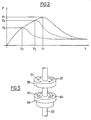
- the curve of variation of the damping force F as a function of the compression speed of the rod V is illustrated in solid lines in FIG. 2.
- the maximum value F1 of the damping force appears for the limiting speed V1 and depends on the reference pressure in the chamber 9 and the preload of the spring 14 also depends on the flow rate of hydraulic fluid passing through the separation piece 24 through the passage piece 38 and the ring 36.
- a rotation of the ring 36 which modifies the number of passages 37 allowing the passage of fluid therefore makes it possible to vary the characteristics of the damper by modifying the opening time of the control valve 11.
- the modified curves are shown in dotted lines in FIG. 2.
- a new limit value V2 less than V2 is obtained and this results in a maximum damping force F2 less than the maximum force F1.
- a maximum compression speed V3 can be obtained corresponding to the opening of the control valve 11 less than V2 the corresponding damping force F3 being less than the damping force F2.
- the cylinder 2 is further delimited at its upper part by an elastic block 21 as has been said previously. It will be noted that the existence of such an elastic block 21 is by no means essential and that the damper of the invention could function perfectly in the absence of such an elastic block.
- the elastic block 21 however plays a role during sudden or very brutal compression on the shock absorber. In this case, in fact, the elastic block 21 compresses even before any movement of the rod 3. This results in a reduction in the useful volume of the first chamber 2 a which causes an increase in the pressure in said chamber and the premature opening. of the control valve 11. The existence of the elastic block 21 therefore prevents the rapid establishment of the damping force, which makes it possible to obtain, on the curves illustrated in FIG. 2, a slightly rounded maximum which improves the comfort of the suspension.
- the damping force is created only by the valve 18 which allows a passage limited by the channels 17 through the piston 1.
- the valve 32 chosen very flexible, plays a simple role of valve make up and practically does not oppose the exit of the hydraulic fluid from the reservoir 19.
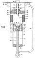
- the reservoir 19 is under pressure greater than atmospheric pressure so as to avoid any cavitation of hydraulic fluid in the first chamber 2 a during a detent movement of the rod 3.
- the reservoir 19 is placed in communication by the flexible pipe 45 with a axial pipe 46 located in the rod 3 and in communication with the chamber 9.
- the reference chamber 9 is therefore at the same pressure, greater than atmospheric pressure, as the reservoir 19.
- the non-return valve 47 is mounted directly between the ring 48 and a spacer 49.
- the rigidity of the valve 47, the peripheral zone of which blocks the passages 35, is chosen so as to cause a reduction in pressure in the first chamber 2 a during a rapid expansion movement of the rod 3.
- the valve 47 therefore does not play, as was the case for valve 32 of the embodiment of FIG. 1, a simple role of replenishing the hydraulic fluid coming from the reservoir 19.
- FIG. 5 illustrates by way of example an application of the invention to a shock absorber whose general structure is identical to that of the shock absorbers illustrated in FIGS. 1 and 4 but which includes means controlled independently to vary the operating characteristics of the shock absorber not only during a compression movement but also during an expansion movement.
- identical parts have the same references.
- the separation piece 24 is equipped with two assemblies operating alternately during a compression movement or during an expansion movement. For a compression movement, we find on the left of the Figure 5 controlled means similar to those already illustrated in Figures 1 and 4.
- the passages 39 a we find in the passage piece 38 a the passages 39 a while the curved grooves 40 a which play the same role as the grooves 40 of the passage piece 38 are formed directly on the upper front surface of the separation piece 24 of to cooperate with the various passageways 37 in the ring 36 which are arranged in groups as was the case for the passages 37 of the ring 36.
- the hydraulic fluid can therefore pass through a number of passages 37 a and then by grooves 40 a and passages 39 b located in the separation piece 24, penetrate the passages 39 a of the passage piece 38 a .
- a very flexible non-return valve 83 prevents the passage of the fluid through the separation piece 24 in the other direction, that is to say from the first chamber 2 a to the reservoir 19.
- the separation piece 24 also has passages 84 closed by a relatively rigid non-return valve 85 held between the separation piece 24 and a shoulder of the passage piece 38 a .
- control motors 26 and 26 a are normally associated with potentiometers or angular encoders making it possible to measure the position of the shafts 25 and 25 a so as to ensure that the flow of fluid controlled through the various restrictions is indeed the desired flow.
- motors 26 and 26 has stepping motors which are then systematically abutted when the vehicle is started. The exact position of the shafts 25 and 25 a is then obtained by counting and counting down the pulses causing the motors to rotate in one direction or the other.
- the structure of the controlled means as it has been described hitherto, that is to say comprising the rotary shafts 25 and 25 a carrying the rotary rings 36 and 36 a can be replaced by other means of classic type.
- shock absorber of the invention can be easily done by means located in a part of the shock absorber linked to the body of the vehicle, which makes it possible to arrange the electrical control member such as the motors 26 and 26 to outside the enclosure filled with damper oil.
- the connections between the parts altering the flow rate through the restrictions and actuators such as motors 26 and 26 a are provided with rigid axles.
- the motors 26 and 26 a can be controlled independently. It is also possible in certain cases to simplify the control by acting in the same way on the two motors 26 and 26 a , or even by replacing them with a single motor linked to the control means by two appropriate transmissions.
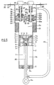
- FIG. 6 illustrates by way of example an application of the invention on a two-tube type shock absorber.
- the cylinder 2 comprises in its upper part a control part 6 to which is fixed, by means not shown, an upper closing part 50.
- An outer cylindrical envelope 51, concentric with the cylinder 2, serves as a housing for all of the elements of the damper and is integral with the lower closure part 5 and the upper closure part 50.
- the control piece 6 defines with the upper closing piece 50 an intermediate space 52 and a reference chamber 53 separated by a flexible membrane 54 hermetic to gases and kept clamped between two respective front surfaces of the control piece 6 and the piece upper closure 50.
- the reference chamber 53 is filled with a gas at a substantially constant reference pressure.
- the control part 6 has a central bore 55 having on its upper part a valve seat 56 on which comes to bear a substantially conical portion 57 of the control valve which has an upper portion 57a integral with the membrane 54.
- the valve 57 also has the opposite of the portion 57 has a rod 57 b which passes through the bore 55 and has at its end a washer 58 on which rests a return spring 59 of the control valve 57 which is supported also on the control panel 6.
- the control part 6 further comprises passages 60 capable of bringing the intermediate space 52 into communication with the first chamber 2 a of the cylinder.
- a very flexible non-return valve 61 maintained by means of a nut 62 prevents the circulation of the fluid hydraulics from the first chamber 2 a to the intermediate space 52.
- the control part 6 further comprises radial passages 63 allowing circulation in both directions of the hydraulic fluid between the intermediate space 52 and the annular space 51 b delimited by the cylinder 2 and the concentric outer casing 51.
- Passages 64 and a very flexible non-return valve 65 held by a nut 66 are provided in the lower part 5 to allow the circulation of the hydraulic fluid from the annular space 51 b towards the second bedroom 2 b and prohibit it in the other direction.
- the upper closing part 50 comprises passages 67 providing communication between the annular space 51b and the portion 51a of the outer casing 51 located above the closure part 50.
- the piston 1 includes passage 68 cooperating with a rigid non-return valve 69 so as to allow a limited passage of hydraulic fluid from the second chamber 2 b to the first chamber 2 a and prohibit any movement in the opposite direction.
- the piston 1 also has passages 70 cooperating with a rigid non-return valve 71 to allow limited circulation of hydraulic fluid from the first chamber 2 a to the second chamber 2 b and to prevent any circulation in the opposite direction.
- Calibrated orifices such as 72 and 73 are provided in the wall of the cylinder 2 in the vicinity respectively of its lower part and its upper part.
- the cylindrical external envelope 51 is closed at its upper part by an elastic elastomer block 74 which is integral with the external wall of the envelope 51 and which is fixed by its external peripheral surface inside a cylindrical sleeve 76 which extends upwards and has in its upper part a fixing flange 77 by means of which the sleeve 76 can be fixed to the body of the motor vehicle 78 by means of screws 80.
- the sleeve 76 constitutes the reservoir of the shock absorber and contains a gas in its upper part 81.
- a flexible hose 82 connects the part 81 of the reservoir with the reference chamber 53 so that said chamber and the reservoir can be placed under high pressure above atmospheric pressure.
- the portion 51a of the cylindrical casing 51 is separated from the tank by a separating part 24 which has the same structure as that which has already been described with reference to the embodiment of Figure 4.
- the include the drive motor 26 which rotates the ring 36 to vary the flow of hydraulic fluid from the upper portion 51a to the reservoir 81 during a compression movement of the rod 3 causing, according the rotation of the shaft 25 a modification of the operating characteristics in compression as was already the case in the embodiment of FIG. 4.
- a rigid valve 47 has been shown here which has the same characteristics as that illustrated in FIG. 4.
- the rod 3 is released, the same action is obtained as described above on the block elastic 74.
- the commands for varying the operating characteristics of the shock absorber can also be carried out manually either directly on the shock absorber or remotely via a mechanical link.
- shock absorbers of the invention therefore make it possible to take account of these different quantities which can be processed by a microprocessor to modify the operating characteristics of the shock absorbers by taking account of the operation and movement of the vehicle.
Landscapes
- Engineering & Computer Science (AREA)
- General Engineering & Computer Science (AREA)
- Mechanical Engineering (AREA)
- Fluid-Damping Devices (AREA)
- Vehicle Body Suspensions (AREA)
Claims (16)
Applications Claiming Priority (2)
| Application Number | Priority Date | Filing Date | Title |
|---|---|---|---|
| FR8710311 | 1987-07-21 | ||
| FR8710311A FR2618507B1 (fr) | 1987-07-21 | 1987-07-21 | Amortisseur hydraulique muni de moyens permettant de faire varier les caracteristiques de fonctionnement |
Publications (2)
| Publication Number | Publication Date |
|---|---|
| EP0304599A1 EP0304599A1 (de) | 1989-03-01 |
| EP0304599B1 true EP0304599B1 (de) | 1991-10-09 |
Family
ID=9353379
Family Applications (1)
| Application Number | Title | Priority Date | Filing Date |
|---|---|---|---|
| EP88111197A Expired - Lifetime EP0304599B1 (de) | 1987-07-21 | 1988-07-13 | Mit Mitteln zur Änderung der Dämpfungscharakteristik ausgerüsteter hydraulischer Stossdämpfer |
Country Status (6)
| Country | Link |
|---|---|
| US (1) | US4972928A (de) |
| EP (1) | EP0304599B1 (de) |
| JP (1) | JP2831657B2 (de) |
| DE (1) | DE3865399D1 (de) |
| ES (1) | ES2025741T3 (de) |
| FR (1) | FR2618507B1 (de) |
Cited By (1)
| Publication number | Priority date | Publication date | Assignee | Title |
|---|---|---|---|---|
| US6951267B2 (en) | 2003-05-22 | 2005-10-04 | Hyundai Motor Company | Damping force-variable shock absorber |
Families Citing this family (57)
| Publication number | Priority date | Publication date | Assignee | Title |
|---|---|---|---|---|
| US4872537A (en) * | 1988-06-06 | 1989-10-10 | Brian Warner | Adjustable damper means for shock absorber |
| US5158161A (en) * | 1989-07-17 | 1992-10-27 | Atsugi Unisia Corporation | Reverse installation type variable damping force shock absorber variable of damping characteristics both for bounding and rebounding stroke motions |
| AU624729B2 (en) * | 1989-07-17 | 1992-06-18 | Atsugi Unisia Corporation | Reverse installation type variable damping force shock absorber variable of damping characteristics both for bounding and rebounding stroke motions |
| US5129488A (en) * | 1989-11-16 | 1992-07-14 | Atsugi Unisia Corporation | Vibration mode responsive variable damping force shock absorber with feature of automatic selection of damping mode depending upon vibration mode of vehicular body |
| US5490684A (en) * | 1990-10-01 | 1996-02-13 | Leonard Studio Equipment, Inc. | Split chassis camera pedestal |
| US5113979A (en) * | 1991-02-20 | 1992-05-19 | Monroe Auto Equipment Company | Base valve for a shock absorber |
| US5190126A (en) * | 1991-09-16 | 1993-03-02 | Charles Curnutt | Shock absorber with air cavity controlled orifices |
| DE4320446A1 (de) * | 1992-08-08 | 1994-02-10 | Bosch Gmbh Robert | Stoßdämpfer |
| US5295563A (en) * | 1993-03-01 | 1994-03-22 | General Motors Corporation | Active suspension actuator with control flow through the piston rod |
| ATE159474T1 (de) * | 1993-07-23 | 1997-11-15 | Leonard Studio Equip | Kamerawagen |
| US6611743B2 (en) * | 1999-11-11 | 2003-08-26 | Yamaha Hatsudoki Kabushiki Kaisha | Suspension for a motorcycle |
| DE10138195C1 (de) * | 2001-08-03 | 2003-02-06 | Zf Sachs Ag | Schwingungsdämpfer nach dem Einrohrprinzip |
| WO2003102425A2 (en) * | 2002-05-29 | 2003-12-11 | Progressive Suspension, Inc. | Hydraulic dampers with pressure regulated control valve and remote pressure adjustment |
| JP2005214232A (ja) * | 2004-01-27 | 2005-08-11 | Ntn Corp | 補機用オートテンショナ |
| US7562750B2 (en) * | 2004-02-10 | 2009-07-21 | Tenneco Automotive Operating Company Inc. | Air pressure proportional damper for shock absorber |
| US7124865B2 (en) * | 2004-02-13 | 2006-10-24 | Progressive Suspension, Inc. | Pressure regulating dampers |
| US7921973B2 (en) * | 2006-05-31 | 2011-04-12 | Techno-Sciences, Inc. | Adaptive energy absorption system for a vehicle seat |
| US7878312B2 (en) * | 2006-05-31 | 2011-02-01 | University Of Maryland | Adaptive energy absorption system for a vehicle seat |
| US7822522B2 (en) * | 2006-05-31 | 2010-10-26 | Techno-Sciences, Inc. (corporation) | Adaptive energy absorption system for a vehicle seat |
| US9494209B1 (en) | 2007-06-21 | 2016-11-15 | Bill J. Gartner | Regressive hydraulic damper |
| US9150075B2 (en) | 2008-03-19 | 2015-10-06 | Fox Factory, Inc. | Methods and apparatus for suspending vehicles |
| US9156325B2 (en) | 2008-03-19 | 2015-10-13 | Fox Factory, Inc. | Methods and apparatus for vehicle suspension having multiple gas volumes |
| US20100244340A1 (en) * | 2008-03-19 | 2010-09-30 | Wootten Dennis K | Methods and apparatus for combined variable damping and variable spring rate suspension |
| US8869959B2 (en) | 2008-07-24 | 2014-10-28 | Fox Factory, Incorporated | Vehicle suspension damper |
| US8857580B2 (en) | 2009-01-07 | 2014-10-14 | Fox Factory, Inc. | Remotely operated bypass for a suspension damper |
| US10060499B2 (en) | 2009-01-07 | 2018-08-28 | Fox Factory, Inc. | Method and apparatus for an adjustable damper |
| US11306798B2 (en) | 2008-05-09 | 2022-04-19 | Fox Factory, Inc. | Position sensitive suspension damping with an active valve |
| US20100170760A1 (en) | 2009-01-07 | 2010-07-08 | John Marking | Remotely Operated Bypass for a Suspension Damper |
| US8627932B2 (en) | 2009-01-07 | 2014-01-14 | Fox Factory, Inc. | Bypass for a suspension damper |
| US9452654B2 (en) | 2009-01-07 | 2016-09-27 | Fox Factory, Inc. | Method and apparatus for an adjustable damper |
| US10047817B2 (en) | 2009-01-07 | 2018-08-14 | Fox Factory, Inc. | Method and apparatus for an adjustable damper |
| US8393446B2 (en) | 2008-08-25 | 2013-03-12 | David M Haugen | Methods and apparatus for suspension lock out and signal generation |
| DE102008057268A1 (de) * | 2008-11-13 | 2010-05-20 | Dt Swiss Ag | Federgabel für ein Fahrrad |
| DE102008057269A1 (de) * | 2008-11-13 | 2010-05-20 | Dt Swiss Ag | Federgabel |
| US9140325B2 (en) | 2009-03-19 | 2015-09-22 | Fox Factory, Inc. | Methods and apparatus for selective spring pre-load adjustment |
| US9422018B2 (en) | 2008-11-25 | 2016-08-23 | Fox Factory, Inc. | Seat post |
| US10036443B2 (en) | 2009-03-19 | 2018-07-31 | Fox Factory, Inc. | Methods and apparatus for suspension adjustment |
| US12491961B2 (en) | 2008-11-25 | 2025-12-09 | Fox Factory, Inc. | Seat post |
| US9038791B2 (en) | 2009-01-07 | 2015-05-26 | Fox Factory, Inc. | Compression isolator for a suspension damper |
| US11299233B2 (en) | 2009-01-07 | 2022-04-12 | Fox Factory, Inc. | Method and apparatus for an adjustable damper |
| US9556925B2 (en) * | 2009-01-07 | 2017-01-31 | Fox Factory, Inc. | Suspension damper with by-pass valves |
| US8936139B2 (en) | 2009-03-19 | 2015-01-20 | Fox Factory, Inc. | Methods and apparatus for suspension adjustment |
| US8838335B2 (en) | 2011-09-12 | 2014-09-16 | Fox Factory, Inc. | Methods and apparatus for suspension set up |
| US8672106B2 (en) | 2009-10-13 | 2014-03-18 | Fox Factory, Inc. | Self-regulating suspension |
| EP2312180B1 (de) | 2009-10-13 | 2019-09-18 | Fox Factory, Inc. | Vorrichtung zur Steuerung eines hydraulischen Dämpfers |
| JP5519255B2 (ja) * | 2009-11-30 | 2014-06-11 | 三井造船株式会社 | 岸壁クレーン |
| US10697514B2 (en) | 2010-01-20 | 2020-06-30 | Fox Factory, Inc. | Remotely operated bypass for a suspension damper |
| EP2530355B1 (de) | 2011-05-31 | 2019-09-04 | Fox Factory, Inc. | Vorrichtungen für lageempfindliche und/oder anpassbare Aufhängungsdämpfung |
| US8950558B2 (en) | 2011-12-29 | 2015-02-10 | Fox Factory, Inc. | Dampers with thermal expansion compensation |
| US11279199B2 (en) | 2012-01-25 | 2022-03-22 | Fox Factory, Inc. | Suspension damper with by-pass valves |
| US10330171B2 (en) | 2012-05-10 | 2019-06-25 | Fox Factory, Inc. | Method and apparatus for an adjustable damper |
| DE112014003754B4 (de) * | 2013-08-14 | 2023-10-05 | Tenneco Automotive Operating Company Inc. | Verfahren zum Zusammenbauen eines Niederdruck-Einrohr-Stossdämpfer mit hoher Einfederungsdämpfung |
| US10737546B2 (en) | 2016-04-08 | 2020-08-11 | Fox Factory, Inc. | Electronic compression and rebound control |
| US11970041B2 (en) * | 2019-02-22 | 2024-04-30 | Fox Factory, Inc. | Adjustable air chamber for a shock |
| CN110748597B (zh) * | 2019-11-11 | 2020-05-15 | 深圳奥景源科技有限公司 | 一种复合减震器 |
| EP4100660A2 (de) | 2020-02-07 | 2022-12-14 | Timoney Dynamic Solutions Limited | Gasfeder für eine kraftfahrzeugaufhängung |
| CN112081852B (zh) * | 2020-09-21 | 2024-12-10 | 广州大学 | 一种变阻尼半主动阻尼器 |
Family Cites Families (13)
| Publication number | Priority date | Publication date | Assignee | Title |
|---|---|---|---|---|
| DE354053C (de) * | 1922-06-01 | Robert Woerner | Stuetzraederanordnung fuer zweiraedrige, einen Wagenkasten tragende Motorfahrzeuge | |
| US2182016A (en) * | 1936-12-22 | 1939-12-05 | Deutsch Fritz Albert | Fluid retarding or braking device |
| BE491915A (de) * | 1948-11-10 | 1900-01-01 | ||
| FR2287627A1 (fr) * | 1974-10-11 | 1976-05-07 | Sirven Jacques | Amortisseur hydraulique de suspension de vehicule |
| FR2415752A1 (fr) * | 1978-01-25 | 1979-08-24 | Sirven Jacques | Amortisseur hydraulique de suspension de vehicule |
| JPS54111064A (en) * | 1978-02-18 | 1979-08-31 | Honda Motor Co Ltd | Damping-force adjusting apparatus in hydraulic shock- absorber |
| FR2497896A1 (fr) * | 1980-08-29 | 1982-07-16 | Messier Hispano Sa | Amortisseur |
| GB2101266B (en) * | 1981-07-09 | 1985-08-21 | Lucas Industries Ltd | Self-pumping struts for vehicle suspension systems |
| JPS5872744A (ja) * | 1981-10-28 | 1983-04-30 | Kayaba Ind Co Ltd | 複筒型油圧緩衝器の減衰力調整装置 |
| JPS60179315A (ja) * | 1984-02-28 | 1985-09-13 | Nhk Spring Co Ltd | 車両用懸架装置 |
| JPS61108543U (de) * | 1984-12-20 | 1986-07-09 | ||
| FR2575254B1 (fr) * | 1984-12-20 | 1989-06-02 | Sirven Jacques | Amortisseur pour suspension de vehicule automobile |
| DE3523628A1 (de) * | 1985-07-02 | 1987-01-15 | Bayerische Motoren Werke Ag | Ventilsystem fuer steuerbare, hydraulische schwingungsdaempfer |
-
1987
- 1987-07-21 FR FR8710311A patent/FR2618507B1/fr not_active Expired - Fee Related
-
1988
- 1988-07-11 US US07/217,360 patent/US4972928A/en not_active Expired - Fee Related
- 1988-07-13 ES ES198888111197T patent/ES2025741T3/es not_active Expired - Lifetime
- 1988-07-13 EP EP88111197A patent/EP0304599B1/de not_active Expired - Lifetime
- 1988-07-13 DE DE8888111197T patent/DE3865399D1/de not_active Expired - Lifetime
- 1988-07-21 JP JP63180438A patent/JP2831657B2/ja not_active Expired - Lifetime
Cited By (1)
| Publication number | Priority date | Publication date | Assignee | Title |
|---|---|---|---|---|
| US6951267B2 (en) | 2003-05-22 | 2005-10-04 | Hyundai Motor Company | Damping force-variable shock absorber |
Also Published As
| Publication number | Publication date |
|---|---|
| JP2831657B2 (ja) | 1998-12-02 |
| US4972928A (en) | 1990-11-27 |
| DE3865399D1 (de) | 1991-11-14 |
| JPS6440732A (en) | 1989-02-13 |
| ES2025741T3 (es) | 1992-04-01 |
| EP0304599A1 (de) | 1989-03-01 |
| FR2618507B1 (fr) | 1993-12-03 |
| FR2618507A1 (fr) | 1989-01-27 |
Similar Documents
| Publication | Publication Date | Title |
|---|---|---|
| EP0304599B1 (de) | Mit Mitteln zur Änderung der Dämpfungscharakteristik ausgerüsteter hydraulischer Stossdämpfer | |
| EP0003290B1 (de) | Hydraulischer Dämpfer für Fahrzeugaufhängung | |
| EP0416987B1 (de) | Ventil für hydraulische Flüssigkeit und ein mit einem solchen Ventil ausgerüsteter Dämpfer | |
| EP0275503B1 (de) | Dämpfer mit Lastausgleich | |
| EP0185389B1 (de) | Dämpfer für Kraftfahrzeugaufhängung | |
| FR2594922A1 (fr) | Procede pour regler la force d'amortissement d'un amortisseur | |
| FR2657821A1 (de) | ||
| FR2609129A1 (fr) | Dispositif pour amortir des mouvements, notamment ceux de la suspension d'une automobile | |
| FR2550137A1 (fr) | Dispositif amortisseur d'oscillations pour vehicule automobile | |
| FR2552513A1 (fr) | Appareil de suspension de vehicule | |
| FR2661643A1 (fr) | Suspension de vehicule de type hydropneumatique notamment pour vehicules automobiles. | |
| FR2573365A1 (fr) | Suspension pour vehicule | |
| FR2529284A1 (fr) | Disque amortisseur pour disque d'embrayage | |
| FR2557036A1 (fr) | Suspension hydropneumatique a reglage du niveau pour vehicules | |
| FR3086985A1 (fr) | Amortisseur hydraulique avec reglage automatique suivant une acceleration radiale | |
| FR2596837A1 (fr) | Perfectionnements aux supports antivibratoires de type hydraulique | |
| FR2664007A1 (fr) | Amortisseur hydraulique pilote pour vehicule automobile. | |
| FR3006730A1 (fr) | Amortisseur avec amortissement hydraulique en fin de course | |
| FR2973853A1 (fr) | Amortisseur hydraulique en particulier pour vehicule automobile | |
| EP0430746B1 (de) | Abstützvorrichtung, insbesondere für die Achse einer Hinterradaufhängung an der Karosserie eines Kraftfahrzeuges | |
| EP1193099B1 (de) | Aufhängungstange einer Antriebseinheit eines Kraftfahrzeuges und Aufhängevorrichtung mit einer solchen Stange | |
| FR2621663A1 (fr) | Amortisseur hydraulique du type a force d'amortissement reglable | |
| FR3086359A1 (fr) | Amortisseur hydraulique avec butee hydraulique de fin de course a positionnement auto-ajustable | |
| FR3120017A1 (fr) | Véhicule de type à selle à hauteur ajustable et son procédé de commande | |
| FR3146179A1 (fr) | Amortisseur à inertie variable de suspension pour véhicule automobile |
Legal Events
| Date | Code | Title | Description |
|---|---|---|---|
| PUAI | Public reference made under article 153(3) epc to a published international application that has entered the european phase |
Free format text: ORIGINAL CODE: 0009012 |
|
| AK | Designated contracting states |
Kind code of ref document: A1 Designated state(s): DE ES FR GB IT |
|
| 17P | Request for examination filed |
Effective date: 19890808 |
|
| 17Q | First examination report despatched |
Effective date: 19891019 |
|
| GRAA | (expected) grant |
Free format text: ORIGINAL CODE: 0009210 |
|
| AK | Designated contracting states |
Kind code of ref document: B1 Designated state(s): DE ES FR GB IT |
|
| ITF | It: translation for a ep patent filed | ||
| GBT | Gb: translation of ep patent filed (gb section 77(6)(a)/1977) | ||
| REF | Corresponds to: |
Ref document number: 3865399 Country of ref document: DE Date of ref document: 19911114 |
|
| REG | Reference to a national code |
Ref country code: ES Ref legal event code: FG2A Ref document number: 2025741 Country of ref document: ES Kind code of ref document: T3 |
|
| PLBE | No opposition filed within time limit |
Free format text: ORIGINAL CODE: 0009261 |
|
| STAA | Information on the status of an ep patent application or granted ep patent |
Free format text: STATUS: NO OPPOSITION FILED WITHIN TIME LIMIT |
|
| 26N | No opposition filed | ||
| PGFP | Annual fee paid to national office [announced via postgrant information from national office to epo] |
Ref country code: FR Payment date: 19990616 Year of fee payment: 12 |
|
| PGFP | Annual fee paid to national office [announced via postgrant information from national office to epo] |
Ref country code: GB Payment date: 19990706 Year of fee payment: 12 |
|
| PGFP | Annual fee paid to national office [announced via postgrant information from national office to epo] |
Ref country code: ES Payment date: 19990714 Year of fee payment: 12 |
|
| PGFP | Annual fee paid to national office [announced via postgrant information from national office to epo] |
Ref country code: DE Payment date: 19990715 Year of fee payment: 12 |
|
| PG25 | Lapsed in a contracting state [announced via postgrant information from national office to epo] |
Ref country code: GB Free format text: LAPSE BECAUSE OF NON-PAYMENT OF DUE FEES Effective date: 20000713 |
|
| PG25 | Lapsed in a contracting state [announced via postgrant information from national office to epo] |
Ref country code: ES Free format text: LAPSE BECAUSE OF NON-PAYMENT OF DUE FEES Effective date: 20000714 |
|
| GBPC | Gb: european patent ceased through non-payment of renewal fee |
Effective date: 20000713 |
|
| PG25 | Lapsed in a contracting state [announced via postgrant information from national office to epo] |
Ref country code: FR Free format text: LAPSE BECAUSE OF NON-PAYMENT OF DUE FEES Effective date: 20010330 |
|
| REG | Reference to a national code |
Ref country code: FR Ref legal event code: ST |
|
| PG25 | Lapsed in a contracting state [announced via postgrant information from national office to epo] |
Ref country code: DE Free format text: LAPSE BECAUSE OF NON-PAYMENT OF DUE FEES Effective date: 20010501 |
|
| REG | Reference to a national code |
Ref country code: ES Ref legal event code: FD2A Effective date: 20010810 |
|
| PG25 | Lapsed in a contracting state [announced via postgrant information from national office to epo] |
Ref country code: IT Free format text: LAPSE BECAUSE OF NON-PAYMENT OF DUE FEES;WARNING: LAPSES OF ITALIAN PATENTS WITH EFFECTIVE DATE BEFORE 2007 MAY HAVE OCCURRED AT ANY TIME BEFORE 2007. THE CORRECT EFFECTIVE DATE MAY BE DIFFERENT FROM THE ONE RECORDED. Effective date: 20050713 |