EP0241316B1 - Verfahren zur Herstellung einer niedergeschlagenen kristalliner Schicht - Google Patents
Verfahren zur Herstellung einer niedergeschlagenen kristalliner Schicht Download PDFInfo
- Publication number
- EP0241316B1 EP0241316B1 EP87303224A EP87303224A EP0241316B1 EP 0241316 B1 EP0241316 B1 EP 0241316B1 EP 87303224 A EP87303224 A EP 87303224A EP 87303224 A EP87303224 A EP 87303224A EP 0241316 B1 EP0241316 B1 EP 0241316B1
- Authority
- EP
- European Patent Office
- Prior art keywords
- deposition surface
- thin film
- substrate
- silicon
- nucleation
- Prior art date
- Legal status (The legal status is an assumption and is not a legal conclusion. Google has not performed a legal analysis and makes no representation as to the accuracy of the status listed.)
- Expired - Lifetime
Links
Images


Classifications
-
- H—ELECTRICITY
- H10—SEMICONDUCTOR DEVICES; ELECTRIC SOLID-STATE DEVICES NOT OTHERWISE PROVIDED FOR
- H10P—GENERIC PROCESSES OR APPARATUS FOR THE MANUFACTURE OR TREATMENT OF DEVICES COVERED BY CLASS H10
- H10P14/00—Formation of materials, e.g. in the shape of layers or pillars
- H10P14/20—Formation of materials, e.g. in the shape of layers or pillars of semiconductor materials
- H10P14/29—Formation of materials, e.g. in the shape of layers or pillars of semiconductor materials characterised by the substrates
- H10P14/2901—Materials
- H10P14/2922—Materials being non-crystalline insulating materials, e.g. glass or polymers
-
- C—CHEMISTRY; METALLURGY
- C23—COATING METALLIC MATERIAL; COATING MATERIAL WITH METALLIC MATERIAL; CHEMICAL SURFACE TREATMENT; DIFFUSION TREATMENT OF METALLIC MATERIAL; COATING BY VACUUM EVAPORATION, BY SPUTTERING, BY ION IMPLANTATION OR BY CHEMICAL VAPOUR DEPOSITION, IN GENERAL; INHIBITING CORROSION OF METALLIC MATERIAL OR INCRUSTATION IN GENERAL
- C23C—COATING METALLIC MATERIAL; COATING MATERIAL WITH METALLIC MATERIAL; SURFACE TREATMENT OF METALLIC MATERIAL BY DIFFUSION INTO THE SURFACE, BY CHEMICAL CONVERSION OR SUBSTITUTION; COATING BY VACUUM EVAPORATION, BY SPUTTERING, BY ION IMPLANTATION OR BY CHEMICAL VAPOUR DEPOSITION, IN GENERAL
- C23C16/00—Chemical coating by decomposition of gaseous compounds, without leaving reaction products of surface material in the coating, i.e. chemical vapour deposition [CVD] processes
- C23C16/04—Coating on selected surface areas, e.g. using masks
-
- C—CHEMISTRY; METALLURGY
- C23—COATING METALLIC MATERIAL; COATING MATERIAL WITH METALLIC MATERIAL; CHEMICAL SURFACE TREATMENT; DIFFUSION TREATMENT OF METALLIC MATERIAL; COATING BY VACUUM EVAPORATION, BY SPUTTERING, BY ION IMPLANTATION OR BY CHEMICAL VAPOUR DEPOSITION, IN GENERAL; INHIBITING CORROSION OF METALLIC MATERIAL OR INCRUSTATION IN GENERAL
- C23C—COATING METALLIC MATERIAL; COATING MATERIAL WITH METALLIC MATERIAL; SURFACE TREATMENT OF METALLIC MATERIAL BY DIFFUSION INTO THE SURFACE, BY CHEMICAL CONVERSION OR SUBSTITUTION; COATING BY VACUUM EVAPORATION, BY SPUTTERING, BY ION IMPLANTATION OR BY CHEMICAL VAPOUR DEPOSITION, IN GENERAL
- C23C16/00—Chemical coating by decomposition of gaseous compounds, without leaving reaction products of surface material in the coating, i.e. chemical vapour deposition [CVD] processes
- C23C16/22—Chemical coating by decomposition of gaseous compounds, without leaving reaction products of surface material in the coating, i.e. chemical vapour deposition [CVD] processes characterised by the deposition of inorganic material, other than metallic material
- C23C16/24—Deposition of silicon only
-
- C—CHEMISTRY; METALLURGY
- C23—COATING METALLIC MATERIAL; COATING MATERIAL WITH METALLIC MATERIAL; CHEMICAL SURFACE TREATMENT; DIFFUSION TREATMENT OF METALLIC MATERIAL; COATING BY VACUUM EVAPORATION, BY SPUTTERING, BY ION IMPLANTATION OR BY CHEMICAL VAPOUR DEPOSITION, IN GENERAL; INHIBITING CORROSION OF METALLIC MATERIAL OR INCRUSTATION IN GENERAL
- C23C—COATING METALLIC MATERIAL; COATING MATERIAL WITH METALLIC MATERIAL; SURFACE TREATMENT OF METALLIC MATERIAL BY DIFFUSION INTO THE SURFACE, BY CHEMICAL CONVERSION OR SUBSTITUTION; COATING BY VACUUM EVAPORATION, BY SPUTTERING, BY ION IMPLANTATION OR BY CHEMICAL VAPOUR DEPOSITION, IN GENERAL
- C23C16/00—Chemical coating by decomposition of gaseous compounds, without leaving reaction products of surface material in the coating, i.e. chemical vapour deposition [CVD] processes
- C23C16/44—Chemical coating by decomposition of gaseous compounds, without leaving reaction products of surface material in the coating, i.e. chemical vapour deposition [CVD] processes characterised by the method of coating
-
- C—CHEMISTRY; METALLURGY
- C30—CRYSTAL GROWTH
- C30B—SINGLE-CRYSTAL GROWTH; UNIDIRECTIONAL SOLIDIFICATION OF EUTECTIC MATERIAL OR UNIDIRECTIONAL DEMIXING OF EUTECTOID MATERIAL; REFINING BY ZONE-MELTING OF MATERIAL; PRODUCTION OF A HOMOGENEOUS POLYCRYSTALLINE MATERIAL WITH DEFINED STRUCTURE; SINGLE CRYSTALS OR HOMOGENEOUS POLYCRYSTALLINE MATERIAL WITH DEFINED STRUCTURE; AFTER-TREATMENT OF SINGLE CRYSTALS OR A HOMOGENEOUS POLYCRYSTALLINE MATERIAL WITH DEFINED STRUCTURE; APPARATUS THEREFOR
- C30B25/00—Single-crystal growth by chemical reaction of reactive gases, e.g. chemical vapour-deposition growth
- C30B25/02—Epitaxial-layer growth
- C30B25/18—Epitaxial-layer growth characterised by the substrate
-
- H—ELECTRICITY
- H10—SEMICONDUCTOR DEVICES; ELECTRIC SOLID-STATE DEVICES NOT OTHERWISE PROVIDED FOR
- H10P—GENERIC PROCESSES OR APPARATUS FOR THE MANUFACTURE OR TREATMENT OF DEVICES COVERED BY CLASS H10
- H10P14/00—Formation of materials, e.g. in the shape of layers or pillars
- H10P14/20—Formation of materials, e.g. in the shape of layers or pillars of semiconductor materials
- H10P14/24—Formation of materials, e.g. in the shape of layers or pillars of semiconductor materials using chemical vapour deposition [CVD]
-
- H—ELECTRICITY
- H10—SEMICONDUCTOR DEVICES; ELECTRIC SOLID-STATE DEVICES NOT OTHERWISE PROVIDED FOR
- H10P—GENERIC PROCESSES OR APPARATUS FOR THE MANUFACTURE OR TREATMENT OF DEVICES COVERED BY CLASS H10
- H10P14/00—Formation of materials, e.g. in the shape of layers or pillars
- H10P14/20—Formation of materials, e.g. in the shape of layers or pillars of semiconductor materials
- H10P14/27—Formation of materials, e.g. in the shape of layers or pillars of semiconductor materials using selective deposition, e.g. simultaneous growth of monocrystalline and non-monocrystalline semiconductor materials
- H10P14/271—Formation of materials, e.g. in the shape of layers or pillars of semiconductor materials using selective deposition, e.g. simultaneous growth of monocrystalline and non-monocrystalline semiconductor materials characterised by the preparation of substrate for selective deposition
-
- H—ELECTRICITY
- H10—SEMICONDUCTOR DEVICES; ELECTRIC SOLID-STATE DEVICES NOT OTHERWISE PROVIDED FOR
- H10P—GENERIC PROCESSES OR APPARATUS FOR THE MANUFACTURE OR TREATMENT OF DEVICES COVERED BY CLASS H10
- H10P14/00—Formation of materials, e.g. in the shape of layers or pillars
- H10P14/20—Formation of materials, e.g. in the shape of layers or pillars of semiconductor materials
- H10P14/27—Formation of materials, e.g. in the shape of layers or pillars of semiconductor materials using selective deposition, e.g. simultaneous growth of monocrystalline and non-monocrystalline semiconductor materials
- H10P14/276—Lateral overgrowth
-
- H—ELECTRICITY
- H10—SEMICONDUCTOR DEVICES; ELECTRIC SOLID-STATE DEVICES NOT OTHERWISE PROVIDED FOR
- H10P—GENERIC PROCESSES OR APPARATUS FOR THE MANUFACTURE OR TREATMENT OF DEVICES COVERED BY CLASS H10
- H10P14/00—Formation of materials, e.g. in the shape of layers or pillars
- H10P14/20—Formation of materials, e.g. in the shape of layers or pillars of semiconductor materials
- H10P14/29—Formation of materials, e.g. in the shape of layers or pillars of semiconductor materials characterised by the substrates
- H10P14/2901—Materials
- H10P14/2902—Materials being Group IVA materials
- H10P14/2905—Silicon, silicon germanium or germanium
-
- H—ELECTRICITY
- H10—SEMICONDUCTOR DEVICES; ELECTRIC SOLID-STATE DEVICES NOT OTHERWISE PROVIDED FOR
- H10P—GENERIC PROCESSES OR APPARATUS FOR THE MANUFACTURE OR TREATMENT OF DEVICES COVERED BY CLASS H10
- H10P14/00—Formation of materials, e.g. in the shape of layers or pillars
- H10P14/20—Formation of materials, e.g. in the shape of layers or pillars of semiconductor materials
- H10P14/32—Formation of materials, e.g. in the shape of layers or pillars of semiconductor materials characterised by intermediate layers between substrates and deposited layers
- H10P14/3202—Materials thereof
- H10P14/3238—Materials thereof being insulating materials
-
- H—ELECTRICITY
- H10—SEMICONDUCTOR DEVICES; ELECTRIC SOLID-STATE DEVICES NOT OTHERWISE PROVIDED FOR
- H10P—GENERIC PROCESSES OR APPARATUS FOR THE MANUFACTURE OR TREATMENT OF DEVICES COVERED BY CLASS H10
- H10P14/00—Formation of materials, e.g. in the shape of layers or pillars
- H10P14/20—Formation of materials, e.g. in the shape of layers or pillars of semiconductor materials
- H10P14/34—Deposited materials, e.g. layers
- H10P14/3402—Deposited materials, e.g. layers characterised by the chemical composition
- H10P14/3404—Deposited materials, e.g. layers characterised by the chemical composition being Group IVA materials
- H10P14/3411—Silicon, silicon germanium or germanium
Definitions
- This invention relates to a method for forming a crystalline silicon deposited film, particularly to a method for forming a crystalline silicon deposited film controlled in grain size and prepared by utilising the difference in nucleation density of silicon according to the kinds of the deposition surface materials.
- the present invention is applicable for formation of a crystalline silicon deposited film to be used for electronic devices, optical devices, magnetic devices, piezoelectric devices or surface acoustic devices, etc., such as semiconductor integrated circuits, optical integrated circuits, magnetic circuits, etc.
- single crystal thin films to be used for semiconductor electronic devices or optical devices have been formed by epitaxial growth on a single crystal substrate.
- epitaxial growth of Si, Ge, GaAs, etc. can be done from liquid phase, gas phase or solid phase on Si single crystal substrate (silicon wafer), and it has been also known that epitaxial growth of a single crystal such as GaAs, GaAlAs, etc., occurs on a GaAs single crystal substrate.
- semiconductor devices and integrated circuits, electroluminescent devices such as semiconductor lasers or LED have been prepared.
- the method for forming a single crystal thin film of the prior art by epitaxial growth may be understood to be dependent greatly on its substrate material.
- Mathews et al have examined about combinations of the substrate material with epitaxial growth layer (EPITAXIAL GROWTH, Academic Press, New York, 1975, ed. by J.W. Mathews).
- the size of the substrate is presently about 6 inches for Si wafer, and enlargement of GaAs, sapphire substrate is further retarded.
- the single crystal substrate is high in production cost, the cost per chip becomes higher.
- the crystal structure of the deposited film becomes amorphous or polycrystalline.
- the amorphous film refers to a state in which near distance order to the extent of the closest atoms is preserved, but no longer distance order exists, while the polycrystalline film refers to single crystal grains having no specific crystal direction gathered as separated at the grain boundaries.
- the deposition temperature is about 600 °C or lower, it becomes an amorphous silicon, while it becomes a polycrystalline silicon with grain sizes distributed between some ten to some hundred nm (some hundred to some thousand ⁇ ) at a temperature higher than said temperature.
- the grain sizes and their distribution of polycrystalline silicon will be varied greatly depending on the formation method.
- the method for forming a polycrystalline thin film with great grain sizes by melting and solidification had the problems that an enormous time is required due to scanning of amorphous or single crystal thin film with energy beam for every wafer to be poor in bulk productivity, and also that it is not suited for enlargement of area.
- US-A-3 620 833 discloses a method of depositing semiconductor single crystals on a substrate comprising a layer of insulating material, such as silicon dioxide, provided with nucleation sites, wherein the substrate is subjecte to a semiconductor (e.g. silicon) process which results in the formation of semiconductor single crystals at the nucleation sites. Hovewer, this document does not disclose sufficient details for implementing the process.
- a semiconductor e.g. silicon
- Diamond thin film which is particularly broad in bandgap as 5.5 eV as the semiconductor, can be actuated at higher temperature (about 500 °C or less) as compared with Si, Ge, GaAs, etc., which are semiconductor materials of the prior art.
- the carrier mobility of both electrons and positive holes surpass that of Si (1800 cm 2 /V ⁇ sec for electrons, 1600 cm 2 /V ⁇ sec for positive holes), and thermal conductivity is also extremely high. For this reason, it has been expected to be promising for application in semiconductor devices of the great consumption power type with great heat generation quantity.
- diamond nuclei are generated by utilizing excitation with microwave, using a hydrocarbon type gas such as CH 4 , etc., and by irradiation with hot filament or electron beam, but the nucleation density is generally low, whereby a continuous thin film can be obtained with difficulty. Even if a continuous thin film may be formed, it has a polycrystalline structure with great grain size distribution and can be difficultly applied for semiconductor device.
- a compensating agent such as hydrogen atoms (H) or halogen atoms(X), etc.
- H hydrogen atoms
- X halogen atoms
- the vacuum vapor deposition method there have been employed the vacuum vapor deposition method, the plasma CVD method, the thermal CVD method, the reactive sputtering method, the ion plating method, the optical CVD method, etc.
- the plasma CVD method has been widely used and industrialized.
- the liquid phase epitaxy is a method for precipitating a semiconductor crystal on a substrate by dissolving a starting material for semiconductor at high temperature to a super-saturated state in a solvent metal which is molten to a liquid and cooling the solution.
- a solvent metal which is molten to a liquid and cooling the solution.
- the gas phase epitaxy has been attempted by physical methods such as the vacuum vapor deposition method, the sputtering method, etc., or chemical methods such as hydrogen reduction of a metal chloride or otherwise thermal pyrolysis of a metal organic compound or a metal hydride.
- the molecular beam epitaxy which is a kind of the vacuum vapor deposition method is a dry process under ultra-high vacuum, and therefore high purification and low temperature growth of crystals are possible, whereby there is the advantage that comoposition and concentration can be well controlled to give a relatively flat deposited film.
- the hydrogen reduction method of a metal chloride or the thermal pyrolysis method of a metal organic compound or a metal hydride are generally called the halide CVD method, the hydride CVD method, MO-CVD method. for these methods, by the reason that a film forming device can be made with relative ease and also as the starting materials, i.e. metal chloride, metal hydrides and organic metals, those with high purities are now readily available, they have studied widely at the present time and application for various devices has been investigated.
- DE-A-3525211 discloses a method of depositing amorphous silicon in which reagent gases are activated in separate chambers before introduction into the reaction chamber.
- gas vapour components used to deposit silicon specifically a chain or cyclic silane compound of which hydrogen atoms are partially or wholly substituted with halogen atoms and one or both of hydrogen gas and halogen gas are activated in separate chambers prior to being brought into the reaction chamber where silicon is to be deposited on the substrate.
- Embodiments of the present invention provide a method for forming a polycrystalline silicon film controlled in grain boundary position, etc., without restriction with respect to the base materials, for example, without restriction with respect to materials, constitutions, sizes, etc., of the substrate.
- Embodiments of the present invention also provide a method for forming the above film with good efficiency according to simple steps without use of a special device.
- Embodiments of the present invention provide a method for forming a deposited film which is easy in control of film quality simultaneously with saving energy and can give a crystalline deposited film having desired characteristics uniformly over a large area and excellent in semiconductive characteristics.
- Embodiments of the present invention provide a method for forming a deposited film which is excellent in productivity and bulk productivity and can form simply and efficiently a crystalline silicon deposited film having high quality and excellent physical characteristics such as electrical, optical or semiconductive characteristics, etc.
- the method for forming a deposited film of the present invention has a specific advantage in forming a deposited film by use of active species without utilising plasma reaction since the plasma CVD method of the prior art forms plasma discharging by permitting discharging energy, etc., to act on starting gases for formation of a deposited film.
- the present method is not subject to any bad influence by etching or abnormal discharging, etc., during film formation.
- the method for forming a deposited film of the present invention utilises the reaction of an active species (A) obtained by activating a chain or cyclic silane compound (SX) of which hydrogen atoms are partially or wholly substituted with halogen atoms with an active species (B) formed from activating hydrogen gas, halogen gas or admixture thereof, it requires no high temperature for deposition, and therefore there is no disturbance of structure by heat, and no heating installation during production and no expense accompanied with running thereof are required, whereby a device can be made at a lower cost. It becomes possible to select the substrate material from a wide scope of materials without depending on heat resistance.
- the method is not restricted by the shape and the size of the substrate, and at the same time the starting materials employed may be very small in amounts, whereby the film forming space can be made smaller to improve the yield dramatically.
- the size and locations of the crystal grains can be determined by arranging the locations of the deposition surface areas as desired on the substrate.
- the activated species (A) from the activation space (A) should preferably be selected and used as desired from those having a lifetime of 0.1 sec. or longer, more preferably 1 sec. or longer, optimally 10 sec. or longer, from the standpoint of productivity and easiness in handling, and the constituent elements of the active species (A) become the components constituting the deposited film formed in the film forming space.
- the hydrogen gas, halogen gas or admixture is activated to become the active species (B) by the action of an activation energy in the activation space (B) before introduction into the film forming space, and introduced from the activation space (A) at the same time during formation of the deposited film to undergo chemical mutual reaction with the active species (A) containing constituent elements which become the constituent components of the deposited film formed.
- gaseous or readily gasifiable compounds such as SiF 4 , (SiF 2 ) 5 , (SiF 2 ) 6 , (SiF 2 ) 4 , Si 2 F 6 , Si 3 F 8 , SiHF 3 , SiH 2 F 2 , SiCl 4 , (SiCl 2 ) 5 , SiBr 4 , (SiBr 2 ) 5 , Si 2 Cl 6 , Si 2 Br 6 , SiHCl 3 , SiH 2 Cl 2 , SiH 3 Cl, SiHBr 3 , SiHI 3 , Si 2 Cl 3 F 3 , and the like.
- activation energies such as electrical energies, including microwave, RF, low frequency DC, etc., heat energies such as heater heating, IR-ray heating, etc., photoenergy, etc. in view of respective conditions and the device.
- the halogen gas for forming active species (B) in the activation space (B) may be one of F 2 gas, Cl 2 gas, or gasified Br 2 , or I 2 .
- an inert gas such as helium, argon, neon, etc., may be added.
- the proportion in amount of the above activated species (A) to the activated species (B) to be introduced into the film forming space will depend on the depositing conditions, the kind of the activated species, etc., but may preferably be 10 : 1 to 1 : 10, more preferably 8 : 2 to 4 : 6.
- the deposited film formed according to the present invention can be doped with a dopant impurity element during or after film formation.
- a dopant impurity element there may be employed, as p-type impurity, an element belonging to the group IIIA of the periodic table such as B, Al, Ga, In, Tl, etc. and, as n-type impurity, an element belonging to the group VA of the periodic table such as N, P, As, Sb, Bi, etc. as suitable ones. Particularly, B, Ga, P and Sb are most preferred.
- the amount of the impurity to be doped will depend on the desired electrical and optical characteristics.
- the substance containing such an impurity atoms as the component is preferable to select a compound which is gaseous under normal temperature and normal pressure, or gaseous at least under the conditions for formation of deposited film and can be readily gasified by a suitable gasifying device.
- Such compounds may include PH 3 , P 2 H 4 , PF 3 , PF 5 , PCl 3 , AsH 3 , AsF 3 , AsF 5 , AsCl 3 , SbH 3 , SbF 5 , BiH 3 , BF 3 , BCl 3 , BBr 3 , B 2 H 6 , B 4 H 10 , B 5 H 9 , B 5 H 11 , B 6 H 10 , B 6 H 12 , AlCl 3 , etc.
- the compounds containing impurity element may be used either singly or as a combination of two or more compounds.
- the substances for introduction of impurities may be directly introduced under gaseous state into the film forming space, or alternatively activated previously in the activation space (A) or the activation space (B) or a third activation space (C) before introduction into the film forming space.
- nucleation surfaces By utilising the difference in nucleus formation density according to the kinds of the materials constituting the nucleation surfaces, by arranging the nucleation surfaces scatteringly with a desired pattern on the substrate, desired crystalline deposited film can be formed selectively.
- the substrate to be used for obtaining Si crystal in the present invention for example, those having Si 3 N 4 arranged scatteringly on SiO 2 film or those having SiO 2 covered over Si 3 N 4 film to have partially the subbing Si 3 N 4 exposed may be employed.
- substrates utilize the property of silicon crystal nuclei which are formed with ease on Si 3 N 4 and with difficulty on SiO 2 , and in the method for forming deposited film of the present invention, both amorphous and crystalline materials can be used, provided that they have difference in difficulty and easiness in formation of nuclei.
- the substrate temperature (Ts) during film formation may be set suitably depending on the kind of the deposited film to be formed and the kind of the substrate used.
- the nucleus with the size exceeding rc is called “stable nucleus”, and unless otherwise particularly noted, “nucleus” in the following basic description of the present invention refers to this "stable nucleus". Also, among “stable nucleus”, those with small r are called “initial nucleus”.
- nuclei grow to become shaped in islands, and further grow whereby contact mutually between islands progresses until sometimes coalescence occurs and via a network structure, it becomes finally a continuous film to cover completely over the substrate surface. Following such a process, a thin film is deposited on the substrate.
- the density of nucleus formed per unit area of the substrate surface, the size of nucleus and the nucleation speed are determined depending on the state of the system of deposition, and particularly the interaction between the flying atoms and the substrate surface material is an important factor.
- a specific crystal direction grows in parallel to the substrate due to anisotropy relative to the crystal surface of the interface energy at the interface between the deposited material and the substrate, and when the substrate is amorphous, the crystal direction within the substrate plane is not constant. For this reason, grain boundaries are formed by collision mutually between nuclei or islands, and particularly in the case of collision mutually between islands with some sizes or greater, grain boundaries are formed as such upon occurrence of coalescence. Since the grain boundaries formed do not move easily in the solid phase, the grain sizes are determined at that point.
- the selective deposition method is a method in which a thin film is formed selectively on the substrate by utilizing the differences between the materials in factors influencing nucleus formation in the thin film forming process such as surface energy, attachment coefficient, release coefficient, surface diffusion speed, etc.
- Figs. 2A and 2B are illustrations of the selective deposition method.
- a thin film 2 comprising a material different in the above factors from the substrate 1 is formed at a desired portion.
- a thin film 3 grows only on the thin film 2, whereby it is possible to give rise to a phenomenon that no growth occurs on the substrate 1.
- the thin film 3 formed self-matchingly can be grown, whereby it becomes possible to omit the lithographic step by use of a resist as practiced in the prior art.
- SiO 2 may be used as the substrate 1, and Si, GaAs, silicon nitride as the thin film 2.
- Fig. 3 is a graph showing the change with lapse of time of nucleation density (ND) on the deposited surface of SiO 2 and the deposited surface of silicon nitride.
- the nucleation density (ND) on SiO 2 is saturated at l0 3 cm -2 or less, and the value is not substantially changed even after 20 minutes.
- SiCl 4 gas is diluted with H 2 and deposited according to theCVD method under the conditions of a pressure of 2.27x10 4 Pa (170 Torr) and a temperature of 1000°C.
- Such a phenomenon depends greatly on the difference in adsorption coefficient, release coefficient, surface diffusion coefficient, etc., relative to Si of the material surfaces of SiO 2 and silicon nitride, but the fact that SiO 2 itself is etched by the reaction of SiO 2 with Si atom itself to form silicon monooxide with higher vapor pressure, while no such etching phenomenon occurs on silicon nitride may be also considered to be a cause to effect selective deposition (T. Yonehara, S. Yoshioka, S. Miyazawa, Journal of Applied Physics 53, 6839, (1982)).
- nucleation density difference As shown in the same graph, sufficiently great nucleation density difference ( ⁇ ND) as shown in the same graph can be obtained.
- SiO 2 is desirable as the material for the deposition surface, this is not limitative and sufficiently practical nucleation density difference ( ⁇ ND) can be obtained even by use of SiO x (0 ⁇ x ⁇ 2).
- nucleation density may be sufficiently l0 3 -fold or more in density of nuclei as shown by the same graph, and sufficient selective formation of deposited film can be done with the materials as exemplified below.
- ions of Si, N, etc. may be injected locally into the SiO 2 surface to form a region having excessive Si or N.
- the present invention utilizes selective deposition based on such nucleation density difference ( ⁇ ND) and, by forming a sufficiently minute region of a different kind of material having sufficiently greater nucleation density than the material of the deposition surface, so that a single nucleus may grow on the region, a single crystal is to be grown selectively only at the site where such fine different kind of of material exists.
- ⁇ ND nucleation density difference
- the material with higher nucleation density (for example, Si 3 N 4 ) is not required to be a bulk material, but it may also be formed as a thin film on the surface of base plate of any desired material to form the above crystal formation surface.
- Figs. 4(A) - 4(D) are illustrations of the formation steps showing a first embodiment of the method for forming film according to the present invention
- Figs. 5(A) and 5(B) are perspective views corresponding to Figs. 4(A) and 4(D).
- nucleation surfaces (S NDL ) 12-1, 12-2, of a material different from the substrate 11 enabling the above selective nucleation are arranged sufficiently finely.
- the distance l is set equal to the size of the single crystal region required for formation of semiconductor device or group of devices or greater.
- the nucleation surfaces (S NDL ) 12-1, 12-2 are required to be formed to a sufficiently fine size (area) to the extent that only a single nucleus may be formed.
- the nucleus grows while maintaining the single crystal structure, and become island-shaped single crystal grains 13-1, 13-2, as shown in Fig. 4(B). For forming island-shaped single crystal grains 13-1, 13-2, it is desirable to determine the conditions so that substantially no nucleation may occur at all on other surfaces than the nucleation surfaces (S NDL ) on the substrate 11.
- the crystal direction in the normal line direction of the substrate 11 of the island-shaped single crystal grains 13-1, 13-2 is determined so as to make the interface energy of the material of the substrate 11 and the material forming nucleus minimum.
- surface or interface energy has anisotropy depending on the crystal face.
- the crystal direction within the substrate plane in amorphous substrate is not determined.
- the island-shaped single crystal grains 13-1, 13-2 further grow to become single crystals 13A-1, 13A-2, until the adjacent single crystals 13A-1, 13A-2, contact each other as shown in Fig. 4(C), but since the crystal directions within the substrate plane are not constant, a crystal grain boundary 14 is formed at the intermediate position between the nucleation surfaces (S NDL ) 12-1 and 12-2.
- the single crystals 13A-1, 13A-2 grow three-dimensionally, but crystal faces with slow growth speed appear as the facet. For this reason, the surfaces of single crystals 13A-1, 13A-2 are flattened by etching or polishing, and further the portion of the grain boundary 14 is removed to form thin films of single crystals 15-1, 15-2,... containing no grain boundary in shape of lattices as shown in Fig. 4(D) and Fig. 5(B).
- the size of the single crystal films 15-1, 15-2, ... is determined by the interval 1 between the nucleation surfaces (S NDL ) 12A-1, 12A-2, as described above. That is, by determining appropriately the formation pattern of the nucleation surface (S NDL ) 12A-1, 12A-2, the position of the grain boundary can be controlled to form single crystals with desired sizes at a desired arrangement.
- FIGS. 6(A)-6(D) are illustrations of the formation steps of crystal showing a second embodiment of the present invention.
- a thin film non-nucleation surface (S NDS )5 comprising a material with small nucleation density (ND) enabling selective nucleation is formed
- nucleation surfaces (S NDL )12 comprising a different kind of material with greater nucleation density (ND) are formed with an interval l thereon, and a single crystal layer 15 can be formed in the same manner as in the above embodiment.
- Figs. 7(A)-7(C) are illustrations of the formation steps showing a third embodiment of the present invention
- Figs. 8(A) and 8(B) are perspective views of the substrates in Figs. 7(A) and 7(C).
- recesses 16 with desired size and shape are formed on the amorphous insulating substrate 11, and nucleation surfaces (S NDL ) 12 with sufficiently fine size for forming only single nucleus are formed therein.
- island-shaped single crystal grains 13 are grown similarly as in the first embodiment.
- single crystal grains 13 are grown until embedding the recess 16 to form a single crystal 17.
- Figs. 9(A)-9(C) are illustrations of the formation steps of crystal showing a fourth embodiment of the present invention.
- a thin film non-nucleation surface (S NDS ) 18 comprising a material with small nucleation density(ND) enabling selective nucleation is formed, and recesses 16 with desired size and shape are formed thereon. and, within the recesses are formed minutely nucleation surfaces (S NDL )12 comprising a material with greater nucleation density (ND) which is different from the material forming the nonnucleation surface (S NDS ), and single crystals 17 are formed in the same manner as in the fifth embodiment.
- S NDL minutely nucleation surfaces
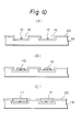
- Figs. 10(A)-10(C) are illustrations of the formation steps of a crystal showing a fifth embodiment of the present invention.
- a thin film nonnucleation surface (S NDS )20 comprising a material with sufficiently small nucleation density (ND) enabling selective nucleation is formed, and following the same procedure as in the above embodiments, single crystals 17 can be formed.
- S NDS thin film nonnucleation surface
- ND nucleation density
- Figs. 11(A)-11(D) are illustrations of the steps for forming crystal showing a sixth embodiment of the present invention.
- Figs. 11(A)-11(C) are the same as Figs. 4(A)-4(C). That is, a plurality (two in the figure) of nucleation surfaces 12 are formed with an interval of l , and single crystal grains 13 subjected to overgrowth on the nucleation surfaces 12 are formed. By permitting the single crystal grains 13 to further grow to form single crystals 13A, a grain boundary 14 is formed approximately at the center between the nucleation surfaces (S NDL ) 12, and by flattening the surface of single crystal 13A, a polycrystalline layer 21 with regular grain sizes which are approximately equal to l as shown in Fig. 11(D) can be obtained.
- the grain size of the polycrystalline layer 21 is determined by the interval l between the nucleation surfaces (S NDL ) 12, it becomes possible to control the grain size of the polycrystal.
- the grain size of a polycrystal was changed by a plural number of factors such as the formation method, formation temperature, etc., and also when preparing a polycrystal with large grain size, it had a grain size distribution with a considerable width.
- the grain size and grain size distribution can be determined with good controllability by the interval l between the nucleation surfaces 12.
- the above polycrystal layer 21 may be formed by forming a non-nucleation surface (S NDS ) 5 with small nucleation density (ND) on a desired substrate 4 and nucleation surfaces (S NDL ) 12-1, 12-2 with greater nucleation density (ND).
- S NDS non-nucleation surface
- S NDL nucleation surfaces
- ND nucleation density
- the substrate material and structure are not limited, but the polycrystal layer 21 can be formed by controlling the grain size and the grain size distribution.
- non-nucleation surface a quartz substrate which is a material with small nucleation density (ND) can be also used as the substrate 11, or alternatively non-nucleation surface (S NDS ) may be provided by forming SiO 2 layer on the surface of any desired base substrate such as metal, semiconductor, magnetic material, piezoelectric material, insulator, etc., by use of the sputtering method, the CVD method, the vacuum vapor deposition method, etc.
- SiO 2 is desirable, but SiO x (0 ⁇ x ⁇ 1) with the value of x being varied may be also employed.
- silicon nitride layer e.g. Si 3 N 4 layer
- a polycrystalline silicon layer e.g. Si 3 N 4 layer
- the silicon nitride layer or polycrystalline silicon layer is subjected to patterning according to conventional lithographic technique or lithographic technique by use of X-ray, electron beam or ion beam, whereby nucleation surface (S NDL ) 12 having fine area of preferably 10 ⁇ m or less, more preferably several micron or less, optimally about 1 ⁇ m or less.
- S NDL nucleation surface
- the substrate temperature, pressure, etc. may be conveniently determined, but the substrate temperature may be preferably 100 to 600 °C.
- grains 13 of single crystals of Si grow on the nucleation surfaces (S NDS ) 12 comprising silicon nitride layer or polycrystalline silicon layer on the SiO 2 layer as the center, and grow to sizes of some 10 ⁇ m or more.
- RIE reactive ion etching
- C-MOS complementary type electrical field effect transistor
- the thickness of the active layer of the device formed is thinner than the case when employing Si wafer, there is no erroneous actuation by the charges generated when radiation is irradiated. Further, due to lowering in unwanted capacity, speed-up of the device can be effected. Also, since any desired substrate can be used, a single crystal layer can be formed on a substrate of large area at lower cost than when employing Si wafer. Further, since a single crystal layer can be formed also on other semiconductors, piezoelectric materials, dielectric materials, etc., a multi-functional three-dimensional integrated circuit can be realized. Thus, the present invention exhibits a number of excellent effects.
- the material for formation of nucleation surface (S NDL ) is not limited to Si 3 N 4 , but silicon nitrides with various chemical composition ratios may be employed.
- the chemical composition ratio of silicon nitride may be varied e.g. as follows.
- the composition ratio of Si and N in the deposited silicon nitride film can be varied to a great extent.
- Fig.12 is a graph showing an example of the relationship between the flow rate ratio of SiH 4 and NH 3 and the composition ratio of Si and N in the silicon nitride film formed.
- the deposition conditions at this time were RF output of 175 W, substrate temperature of 380 °C and the flow rate of NH 3 gas was varied with the SiH 4 gas flow rate being fixed at 300 cc/min.
- the Si/N ratio in the silicon nitride film was found to be varied from 1.1 to 0.58 according to Auger's electron spectrophotometry.
- the silicon nitride film formed by heat treatment of Si at about 1200 °C in ammonia or N 2 can be obtained with a composition further approximate to the stoichiometric ratio, since the formation method is performed under thermal equilibrium.
- the above nucleus of Si can be grown on the nucleation surface (S NDL ) comprising silicon nitride to form Si single crystal based on the nucleation density ( ⁇ ND) corresponding to the chemical composition ratio of silicon nitride.
- Fig. 17 is a graph showing the relationship between Si/N composition ratio and nucleation density (ND). As shown in the same graph, by varying the chemical composition ratio of the silicon nitride film, the nucleation density of the Si single crystal nucleus formed thereon changes to a great extent.
- the nucleation conditions in the graph shown in Fig. 13 correspond to the case when Si single crystal nucleus was formed by reacting SiCl 4 gas reduced to 2.33 Pa (175 Torr) with H 2 at 1000°C. Of course, another graph will be obtained if nucleation conditions such as gas species, pressure, temperature, etc., are changed.
- the phenomenon that the nucleation density thus changes according to the chemical composition ratio of silicon nitride affects the size (area) of the nucleation surface (S NDL ) when employing silicon nitride as the material for forming the nucleation surface (S NDL ) which is formed sufficiently finely to the extent that a single nucleus may be grown. That is, when employing silicon nitride having a composition with great nucleation density (ND) only a single crystal can be formed on the nucleation surface (S NDL ) by forming the nucleation surface (S NDL ) extremely finely as compared with the silicon nitride with relatively smaller nucleation density (ND).
- ND nucleation density
- ND nucleation density
- S NDL size of nucleation surface formed of silicon nitride, etc.
- ND nucleation density
- S NDL size of nucleation surface
- nucleation density difference when forming Si single crystal nucleus
- ion injection of Si, N, P, B, F, Ar, He, C, As, Ga, Ge, etc. may be effected locally onto the SiO 2 surface which is a material for forming non-nucleation surface (S NDS ) with smaller nucleation density to form a modified region with a desired size on the surface of the SiO 2 layer, and utilize this modified region as the nucleation surface (S NDL ) with greater nucleation density (ND).
- S NDS non-nucleation surface
- ND nucleation density
- the SiO 2 layer surface is covered with a photoresist layer and the desired portions are exposed, developed, and dissolved to have the SiO 2 layer surface exposed.
- SiF 4 gas as the source gas, Si ions are implanted onto the SiO 2 layer surface portion exposed at 10 keV at a density of 1 x 10 16 - 1 x 10 18 cm -2 .
- the projected flying distance in this case is 11.4nm (114 ⁇ ), and the Si concentration on the exposed surface of SiO 2 layer reaches about 10 22 cm -3 . Since the SiO 2 layer is originally amorphous, the modified region made excessively enriched in Si by injection of Si ions is also amorphous.
- ion injection can be effected with the use of a resist as the mask, but it is also possible to inject a narrowed Si ion beam selectively at a desired position on the SiO 2 layer surface within a desired area without use of a resist mark by use of converged ion beam technique.
- Si excessive modified region is formed in the SiO 2 layer surface portion at a desired position with a desired size.
- Si single crystal is permitted to grow in vapor phase.
- Fig. 14 is a graph showing the relationship between the injected amount of Si ions and the nucleation density (ND).
- nucleation density is increased as the Si + injected amount is more.
- this modified region sufficiently finely, only single nucleus of Si can be permitted to grow with this modified region as the nucleation surface (S NDL ), whereby a single crystal can be grown as described above.
- Formation of the modified region to a sufficiently fine size to the extent for growth of only a single nucleus can be accomplished easily by patterning of a resist, or narrowing of the beam of converged ion beam.
- Figs. 15(A) - 15(D) are illustrations of the formation steps showing a seventh embodiment of the present invention
- Figs. 16(A) and 16(B) are perspective views corresponding to Figs.15(A) and 15(D).
- an amorphous insulating thin film 12 with relatively greater nucleation density (ND) such as Si 3 N 4 , etc.
- ND nucleation density
- on said thin film 12 is formed selectively a thin film 11 at a desired position with a different material having smaller nucleation density relative to the material forming the thin film 12 which enables the above selective nucleation with an interval of a distance l , thereby arranging nucleation surfaces (S NDL )12A-1, 12A-2 with sufficiently small areas so as to form only single nucleus thereon.
- This distance l may be set at a size which is equal to or greater than the size of the single crystal region required for formation of a semiconductor device or a group of devices.
- the nucleation surfaces (S NDL )12A-1, 12A-2 are required to be formed to a sufficiently fine size (area) to the extent that only a single nucleus may be formed.
- the size of the nucleation surfaces (S NDL )12A-1, 12A-2 which may be different depending on the kind of the material, may be several microns or less. Further, the nucleus formed as above grows while maintaining the single crystal structure, and become island-shaped single crystal grains 13-1, 13-2 as shown in Fig. 15 (B).
- island-shaped single crystal grains 13-1, 13-2 it is desirable to determine the conditions so that substantially no nucleation may occur at all on other surfaces than the nucleation surfaces (S NDL )12A-1, 12A-2 [ non-nucleation surface (S NDS )11A].
- the crystal direction in the normal line d direction of the thin film 12 of the island-shaped single crystal grains 13-1, 13-2 is determined so as to make the interface energy of the material of the film 12 and the material forming nucleus minimum.
- surface or interface energy has anisotropy depending on the crystal face.
- the crystal direction within the surface plane in amorphous surface is not determined.
- the island-shaped single crystal grains 13-1, 13-2 further grow to become single crystals 13A-1, 13A-2 until the adjacent single crystals 13A-1, 13A-2 contact each other as shown in Fig. 15(C), but since the crystal directions within the substrate plane vary from one single crystal to another, a crystal grain boundary 14 is formed at the intermediate position between the nucleation surfaces (S NDL ) 12-1 and 12-2.
- the single crystals 13A-1, 13A-2 grow three-dimensionally, but crystal faces with slow growth speed appear as the facet. For this reason, the surfaces of single crystals 13A-1, 13A-2 are flattened by etching or polishing, and further the portion of the grain boundary 14 is removed to form thin films of single crystals 15-1, 15-2, ... containing no grain boundary in shape of lattices as shown in Fig. 15(D) and Fig. 16(B).
- the size of the single crystal films 15-1, 15-2, ... is determined by the interval 1 between the nucleation surfaces (S NDL )12A-1, 12A-2 as described above. That is, by determining appropriately the formation pattern of the nucleation surface (S NDL ) 12A-1, 12A-2, the position of the grain boundary can be controlled to form single crystal with desired sizes at a desired arrangement.
- Figs. 17 (A) - 17(C) are illustrations of the formation steps showing an eighth embodiment of the present invention
- Figs. 18(A) and 18(B) are perspective views of the substrates in Figs.17(A) and 17(C).
- thin film 12 and 11 are provided on the base substrate 10 to form nucleation surfaces (S NDL )12A-1, 12A-2 and non-nucleation surface (S NDS )11A.
- S NDL nucleation surfaces
- S NDS non-nucleation surface
- a thin film 11-1 is formed with same material as the thin film lla or a material having nucleation density equal to or smaller than said material.
- a substrate for formation of crystal having nucleation surfaces (S NDL )12A-1, 12A-2 with sufficiently fine sizes for forming only single nucleus within recesses 14-1, 14-2 is formded.
- island-shaped single crystal grains 13-1, 13-2 are grown similarly as in the first embodiment.
- single crystal grains 13-1, 13-2 are grown until embedding the concavity 14-1, 14-2 to form single crystals 15-1, 15-2.
- Figs. 19(A) - 19(D) are illustrations of the steps for forming film showing a ninth embodiment of the present invention.
- Figs. 19(A) - 19 (C) are the same as Figs. 15(A) - 15 (C). That is, a plurality (two in the Figure) of nucleation surfaces 12A-1, 12A-2 are formed with an interval of l , and single crystal grains 13-1, 13-2 subjected to over growth on the nucleation surfaces 12A-1, 12A-2 are formed.
- a grain boundary 14 is formed approximately at the center between the non-nucleation surfaces (S NDS )11A, and by flattening the surface of single crystal 13A-1, 13A-2, a polycrystalline layer 16 with regular grain sizes which are approximately equal to l can be obtained.
- the grain size of the polycrystalline layer 16 is determined by the interval l between the nucleation surfaces (S NDL )12A-1, 12A-2, it becomes possible to control the grain size of the polycrystal.
- the grain size of a polycrystal was changed by a plural number of factors such as the formation method, formation temperature, etc., and also when preparing a polycrystal with large grain size, it had a grain size distribution with a considerable width.
- the grain size and grain size distribution can be determined with good controllability by the interval l between the nucleation surfaces (S NDL )12A-1, 12A-2.
- a polycrystal layer may be formed as above by forming a thin film 5 having a non-nucleation surface (S NDS )5A with small nucleation density (ND) on a desired substrate 9 and plural nucleation surfaces (S NDL )9A with greater nucleation density (ND) at desired positions and intervals.
- the substrate material and structure are not limited, provided that the nucleation density difference ( ⁇ ND) is taken into consideration, but the polycrystal layer can be formed by controlling the grain size and the grain size distribution.
- Fig. 20 is a partial sectional view showing the schematic construction of an example of apparatus for forming deposited film in which the process of the present invention is practiced.
- 101 is a deposition chamber (film forming space) in which deposition of silicon thin film is effected, and the deposition chamber 101 is internally connected to an evacuation system not shown through an evacuation outlet 106, whereby the deposition chamber 101 can be maintained at a desired pressure.
- the introducing pipe 102 for radicals (SX) containing e.g., silicon and a halogen which is the active species (A)
- the introducing pipe 103 for e.g., hydrogen radicals as active species (B) respectively.
- the tips of the respective radical introducing pipes are thick at the acting chambers 108, 108A, and narrowed at the outlets 109, 109A.
- a substrate supporting member 104 is held by the roller 110 so as to be movable reciprocally in the direction perpendicular to the paper surface. And on said supporting member 104 is held a support 105 for deposition.
- the respective radicals coming out from the outlet 109, 109A are mixed and reacted with each other in the vicinity of the substrate within the deposition chamber 101 to form a film on the substrate 105.
- the radicals (SX) and hydrogen radicals are formed from the respective starting material gases in the active species forming chambers such as heating furnaces or plasma chambers, etc., not shown, respectively, and thereafter introduced through the introducing pipes 102, 103, respectively into the acting chambers 108, 108A. Their amounts are controlled by massflow controllers on the gas source side from the heating furnace or plasma chamber.
- Roller 110 is provided only for depositing silicon thin film over the whole surface of the substrate by moving the substrate 105.
- the introducing pipe 111 is an introducing pipe for another gas having chemical or physical etching activity (etching gas), and in some cases the etching gas is previously activated in the heating furnace or plasma furnace not shown and led to the outlet 114. From the outlet 114, the etching gas for attacking the film is released to cut or exclude selectively the bonds except in the growth direction of the characteristics of the film.
- Introduction of the etching gas, other than through such separate introduction pipes, can be also done through the introduction pipes 102, 103 mixed with a starting gases, when the reactivity with the starting gases is low.
- the substrate 118 was prepared according to the steps shown in Fig. 21.
- a glass substrate 206 comprising substantially uniform composition material as shown in Fig. 22 (A) was washed and then according to the thermal CVD method amorphous SiN(A-SiN) thin film 207 was formed with a thickness of about 2 ⁇ m on the whole surface of the substrate 206 [Fig. 21(B)].
- the laser was irradiated with Ar-CW laser of 488 nm (4880 ⁇ ), at a scanning speed of 2.5 cm/sec and at an energy of 10 W.
- Ar-CW laser 488 nm (4880 ⁇ )
- the surface of the C-Si 3 N 4 layer 208 was scanned by means of the above laser annealing device in O 2 atmosphere to form locally the SiO 2 layer 209 [Fig. 21(D)].
- the substrate 118 having C-Si 3 N 4 layer 208A exposed at constant intervals with other portions being covered with SiO 2 layer 209 was formed.
- the domains of C-Si 3 N 4 layer 208A exposed on the substrate surface were about 4 ⁇ m in diameter with intervals of 3 ⁇ m.
- Si 2 F 6 as the starting gas for formation of radicals containing silicon and halogen, it was permitted to flow at a flow rate of 100 SCCM into the reaction furnace maintained at 800 °C to be decomposed therein, followed by release through the introducing pipe 102 into the acting chamber 108.
- Ar gas was permitted to flow through the introducing pipe 111 at a rate of 150 SCCM, and a microwave of 2.45 GHz was introduced at a power of 1.0 w/cm 2 into said introducing pipe 103 to effect discharging and decompose H 2 , followed by release of the decomposed gas into the activating chamber 108 at a flow rate of 25 SCCM.
- the substrate temperature was maintained at 270 °C and the pressure at 13.3 Pa (0.1 Torr).
- Fig. 21(E) is a schematic drawing showing the cross-section of the crystalline silicon deposited film 204 obtained on the substrate 118.
- the size of the crystal grain was determined so that the crystal grain boundary 210 was at the same distance from the exposed portions 208A of the crystalline substrate 209 other than the SiO 2 layer 204.
- the smoothness was found to be good without wavy pattern, etc., and the film thickness irregularity was ⁇ 4% or less.
- the mobility and electroconductivity of the crystalline Si deposited film of the sample prepared were measured according to the Van der Pauw method, they were found to be 150 (cm/V ⁇ sec) and 5x10 -6 (S ⁇ cm -1 ), respectively.
- TFT thin film transistor
- an n + layer (specific resistivity ⁇ ⁇ 1 ⁇ cm) which is the ohmic contact layer 3103 doped with P was formed to a thickness of 100 nm (1000 ⁇ ), and then an active layer 3102 was remained by photolithography, followed by etching of the channel portion 3106 to form the above contact layer 3103.
- NH 3 and SiH 4 were decomposed to deposit a Si-N-H film with a film thickness of 300 nm (3000 ⁇ ), dielectric constant of 67 and a dielectric strength 3 x 10 6 V/cm, V FB ⁇ OV at a substrate temperature of 200 °C.
- the method for forming deposited film of the present invention can form a deposited film only by contacting an activated species (A) with an activated species (B), and has the advantage of requiring particularly no reaction exciting energy from the outside. Accordingly, it becomes possible to lower the substrate temperature. Also, since the material for nucleating selectively the crystal nucleus can be arranged at a desired position on the substrate surface, any desired polycrystalline or single crystalline deposited film with extremely high orientation and great grain size can be formed. Further, simultaneously with saving of energy, it is possible to obtain a crystalline deposited film having uniform film quality and characteristics over a large area with easy management of the film quality. Further, a crystalline film excellent in productivity, bulk productivity and having high quality with excellent electrical, optical semiconductive and other physical properties can be obtained with ease.
Landscapes
- Chemical & Material Sciences (AREA)
- Metallurgy (AREA)
- Chemical Kinetics & Catalysis (AREA)
- Engineering & Computer Science (AREA)
- Materials Engineering (AREA)
- General Chemical & Material Sciences (AREA)
- Organic Chemistry (AREA)
- Mechanical Engineering (AREA)
- Inorganic Chemistry (AREA)
- Crystallography & Structural Chemistry (AREA)
- Crystals, And After-Treatments Of Crystals (AREA)
- Laminated Bodies (AREA)
- Chemical Vapour Deposition (AREA)
- Recrystallisation Techniques (AREA)
- Surface Treatment Of Glass (AREA)
Claims (18)
- Verfahren zum Abscheiden von Einzelkristallen aus Silicium auf der Oberfläche eines Substrates mit den Schritten:dadurch gekennzeichnet, daßSchaffen auf einer freien Oberfläche des Substrates einer Vielzahl von Abscheidungsflächenbereichen, die jeweils eine andere Zusammensetzung als die des benachbarten Abscheidungsflächenbereiches besitzen und unter ausgewählten Abscheidungsbedingungen die Eigenschaft aufweisen, Siliciumkerne mit einer höheren Kernbildungsdichte zu bilden als die des benachbarten Abscheidungsflächenbereiches, wobei jeder der Abscheidungsflächenbereiche an voneinander beabstandeten Stellen auf dem Substrat angeordnet ist, die vom benachbarten Abscheidungsflächenbereich getrennt sind; undAbscheiden des Siliciums auf der exponierten freien Oberfläche des Substrates derart, daß die Siliciumkerne selektiv auf der Vielzahl der Abscheidungsflächenbereiche gebildet werden;i) die Vielzahl der Flächenbereiche eine Oberflächeneigenschaft besitzt, die ein epitaxiales Wachstum eines Einzelkristalls aus Silicium ausschließt;ii) jeder aus der Vielzahl der Abscheidungsflächenbereiche auf eine solche Größe beschränkt ist, daß das Silicium auf jedem der Vielzahl der Abscheidungsflächenbereiche unter den ausgewählten Abscheidungsbedingungen nur einen einzigen Kern suprakritischer Größe bildet, der zu einem einzigen Siliciumkristall wächst;iii) die Abscheidung des Siliciums durch die folgenden Schritte durchgeführt wird:Einführen einer kettenförmigen oder zyklischen Silanverbindung, bei der Wasserstoffatome teilweise oder vollständig durch Halogenatome substituiert sind, in eine erste Aktivierungskammer, Ausbilden einer ersten aktivierten Spezies in der ersten Aktivierungskammer aus der kettenförmigen oder zyklischen Silanverbindung durch Verwendung von Aktivierungsenergie;Einführen eines Wasserstoffgases und/oder Halogengases in eine zweite und separate Aktivierungskammer, Ausbilden der aktivierten Spezies in der zweiten und separaten Aktivierungskammer aus dem Wasserstoffgas und/oder einem Halogengas durch Verwendung von Aktivierungsenergie; und dannBringen der ersten und zweiten aktivierten Spezies aus der ersten und zweiten Aktivierungskammer in eine Reaktionskammer, die das Substrat enthält, wodurch die erste und zweite aktivierte Spezies in chemischen Kontakt kommen und eine Vielzahl von angeregten Vorläufern bilden, von denen mindestens einer die Siliciumquelle für die Einzelkristalle aus Silicium bildet.
- Verfahren nach Anspruch 1, bei dem das Halogengas Fluorgas ist.
- Verfahren nach Anspruch 1, bei dem das Halogengas Chlorgas ist.
- Verfahren nach einem der vorangehenden Ansprüche, bei dem eine Verbindung, die aus PH3, P2 H4, PF3, PF5, PCl3, AsH3, AsF3, AsF5, AsCl3, SbH3, SbF5, BiH3, BF3, BCl3, BBr3, B2 H6, B4 H10, B5 H11, B6 H10, B6 H12, AlCl3 ausgewählt ist, im gasförmigen Zustand direkt in die Reaktionskammer eingeführt wird, um das abgeschiedene Silicium mit einer Verunreinigung zu dotieren.
- Verfahren nach einem der Ansprüche 1 bis 3, bei dem eine Verbindung, die aus PH3, P2 H4, PF3, PF5, PCl3, AsH3, AsF3, AsF5, AsCl3, SbH3, SbF5, BiH3, BF3, BCl3, BBr3, B2 H6, B4 H10, B5 H11, B6 H10, B6 H12, AlCl3, ausgewählt ist, in der ersten oder zweiten Aktivierungskammer oder in einer dritten Aktivierungskammer aktiviert und dann in die Reaktionskammer eingeführt wird, um das abgeschiedene Silicium mit einer Verunreinigung zu dotieren.
- Verfahren nach einem der vorangehenden Ansprüche, bei dem die Vielzahl der Abscheidungsflächenbereiche aus amorphem Material besteht.
- Verfahren nach einem der vorangehenden Ansprüche, bei dem der benachbarte Abscheidungsflächenbereich aus Siliciumoxid besteht und die Vielzahl der Abscheidungflächenbereiche aus Siliciumnitrid besteht.
- Verfahren nach einem der Ansprüche 1 bis 6, bei dem der benachbarte Abscheidungsflächenbereich aus Siliciumdioxid besteht und die Vielzahl der Abscheidungsflächenbereiche Bereiche aus Siliciumdioxid, das mit Ionen implantiert ist, die aus Si, N, P, B, F, Ar, He, C, As, Ga oder Ge ausgewählt sind, sind.
- Verfahren nach Anspruch 1, bei dem der benachbarte Abscheidungsflächenbereich eine Oberfläche eines amorphen isolierenden Substrates ist und die Vielzahl der Abscheidungsflächenbereiche aus einem Material besteht, das sich von dem Material des benachbarten Abscheidungsflächenbereiches unterscheidet, und bei dem die Vielzahl der Abscheidungsflächenbereiche auf dem benachbarten Abscheidungsflächenbereich angeordnet ist.
- Verfahren nach Anspruch 1, bei dem der benachbarte Abscheidungsflächenbereich eine Oberfläche eines Dünnfilmes ist und die Vielzahl der Abscheidungsflächenbereiche aus einem Material besteht, das sich von dem Material des benachbarten Abscheidungsflächenbereiches unterscheidet, und bei dem die Vielzahl der Abscheidungsflächenbereiche auf dem benachbarten Abscheidungsflächenbereich angeordnet ist.
- Verfahren nach Anspruch 1, bei dem der benachbarte Abscheidungsflächenbereich eine Oberfläche aus einem amorphen isolierenden Substrat ist, das Ausnehmungen aufweist, bei dem die Vielzahl der Abscheidungsflächenbereiche aus einem Material besteht, das sich von dem Material des benachbarten Abscheidungsflächenbereiches unterscheidet, und bei dem einer aus der Vielzahl der Abscheidungsflächenbereiche auf der Oberfläche der Basis einer entsprechenden Ausnehmung vorgesehen ist.
- Verfahren nach Anspruch 1, bei dem der benachbarte Abscheidungsflächenbereich eine Oberfläche aus einem Dünnfilm ist, der Ausnehmungen aufweist und sich auf der Oberfläche eines Substrates befindet, und bei dem die Vielzahl der Abscheidungsflächenbereiche aus einem Material besteht, das sich von dem Material des benachbarten Abscheidungsflächenbereiches unterscheidet, und bei dem einer aus der Vielzahl der Abscheidungsflächenbereiche auf der Oberfläche der Basis von einer entsprechenden Ausnehmung vorgesehen ist.
- Verfahren nach Anspruch 1, bei dem der benachbarte Abscheidungsflächenbereich eine Oberfläche aus einem Dünnfilm ist, der sich auf einer Oberfläche eines Substrates mit Ausnehmungen befindet, und bei dem einer der Vielzahl der Abscheidungsflächenbereiche auf dem benachbarten Abscheidungsflächenbereich auf der Basis einer entsprechenden Ausnehmung vorgesehen ist.
- Verfahren nach Anspruch 1, bei dem der benachbarte Abscheidungsflächenbereich eine Oberfläche eines ersten Dünnfilmes ist, der auf einem zweiten amorphen isolierenden Dünnfilm aus einem Material, das sich vom Material des benachbarten Abscheidungsflächenbereiches unterscheidet, angeordnet ist, und bei dem die Vielzahl der Abscheidungsflächenbereiche entsprechende Bereiche der Oberfläche des zweiten amorphen isolierenden Dünnfilmes sind, die an Öffnungen des ersten Dünnfilmes exponiert sind.
- Verfahren nach Anspruch 1, bei dem das Substrat ein Basissubstrat, einen ersten Dünnfilm auf der Oberfläche des Basissubstrates, einen zweiten Dünnfilm auf der Oberfläche des ersten Dünnfilmes und einen dritten Dünnfilm auf der Oberfläche des zweiten Dünnfilmes umfasst, wobei der dritte Dünnfilm mit einer Vielzahl von Ausnehmungen versehen ist, die entsprechende Bereiche des zweiten Dünnfilmes freigeben, der zweite Dünnfilm entsprechende Öffnungen an der Basis einer jeden entsprechenden Ausnehmung aufweist, die entsprechende Bereiche des ersten Dünnfilmes freigeben, der benachbarte Abscheidungsflächenbereich die freiliegende Oberfläche des zweiten und dritten Dünnfilmes ist, die Vielzahl der Abscheidungsflächenbereiche von den Bereichen des freiliegenden ersten Dünnfilmes gebildet wird und der dritte Dünnfilm unter den ausgewählten Abscheidungsbedingungen die Eigenschaft besitzt, Siliciumkerne mit einer Kernbildungsdichte zu bilden, die der des zweiten Dünnfilmes entspricht oder niedriger als diese ist.
- Verfahren nach einem der Ansprüche 9, 10 oder 14, bei dem ein aus jedem Einzelkern gewachsenes Einzelkristall solange wachsen gelassen wird, bis benachbarte Einzelkristalle einander kontaktieren.
- Verfahren nach Anspruch 16, bei dem die Oberflächen der Einzelkristalle durch Ätzen oder Polieren eingeebnet werden.
- Verfahren nach Anspruch 17, bei dem die zwischen den Einzelkristallen gebildeten Korngrenzen entfernt werden.
Applications Claiming Priority (4)
| Application Number | Priority Date | Filing Date | Title |
|---|---|---|---|
| JP8393086 | 1986-04-11 | ||
| JP83930/86 | 1986-04-11 | ||
| JP85516/87 | 1987-04-06 | ||
| JP62085516A JP2692804B2 (ja) | 1986-04-11 | 1987-04-06 | 結晶性堆積膜の形成方法 |
Publications (3)
| Publication Number | Publication Date |
|---|---|
| EP0241316A2 EP0241316A2 (de) | 1987-10-14 |
| EP0241316A3 EP0241316A3 (de) | 1988-09-21 |
| EP0241316B1 true EP0241316B1 (de) | 1998-07-22 |
Family
ID=26424966
Family Applications (1)
| Application Number | Title | Priority Date | Filing Date |
|---|---|---|---|
| EP87303224A Expired - Lifetime EP0241316B1 (de) | 1986-04-11 | 1987-04-13 | Verfahren zur Herstellung einer niedergeschlagenen kristalliner Schicht |
Country Status (5)
| Country | Link |
|---|---|
| EP (1) | EP0241316B1 (de) |
| AT (1) | ATE168821T1 (de) |
| AU (2) | AU7143987A (de) |
| CA (1) | CA1329756C (de) |
| DE (1) | DE3752203T2 (de) |
Families Citing this family (8)
| Publication number | Priority date | Publication date | Assignee | Title |
|---|---|---|---|---|
| JPH02258689A (ja) * | 1989-03-31 | 1990-10-19 | Canon Inc | 結晶質薄膜の形成方法 |
| JP2577090B2 (ja) * | 1989-08-07 | 1997-01-29 | キヤノン株式会社 | 結晶半導体膜の形成方法 |
| US5278092A (en) * | 1989-08-07 | 1994-01-11 | Canon Kabushiki Kaisha | Method of forming crystal semiconductor film |
| FR2666172B1 (fr) * | 1990-08-24 | 1997-05-16 | Thomson Csf | Transistor de puissance et procede de realisation. |
| JPH04165672A (ja) * | 1990-10-29 | 1992-06-11 | Mitsubishi Electric Corp | 埋込み型光電子集積素子の製造方法 |
| JP2753153B2 (ja) * | 1991-04-15 | 1998-05-18 | キヤノン株式会社 | 発光素子 |
| DE19845792A1 (de) * | 1998-09-21 | 2000-03-23 | Inst Halbleiterphysik Gmbh | Verfahren zur Erzeugung einer amorphen oder polykristallinen Schicht auf einem Isolatorgebiet |
| GB2362754A (en) * | 2000-05-25 | 2001-11-28 | Nanogate Ltd | A method of growing single crystals |
Citations (2)
| Publication number | Priority date | Publication date | Assignee | Title |
|---|---|---|---|---|
| US3620833A (en) * | 1966-12-23 | 1971-11-16 | Texas Instruments Inc | Integrated circuit fabrication |
| DE3525211A1 (de) * | 1984-07-16 | 1986-01-16 | Canon K.K., Tokio/Tokyo | Vorrichtung zur bildung eines aufgedampften bzw. abgeschiedenen films |
Family Cites Families (6)
| Publication number | Priority date | Publication date | Assignee | Title |
|---|---|---|---|---|
| DE2151346C3 (de) * | 1971-10-15 | 1981-04-09 | Deutsche Itt Industries Gmbh, 7800 Freiburg | Verfahren zum Herstellung einer aus Einkristallschichtteilen und Polykristallschichtteilen bestehenden Halbleiterschicht auf einem Einkristallkörper |
| JPS5767938A (en) * | 1980-10-16 | 1982-04-24 | Canon Inc | Production of photoconductive member |
| JPS6046074B2 (ja) * | 1981-06-30 | 1985-10-14 | 日本電信電話株式会社 | 半導体結晶成長方法 |
| US4443488A (en) * | 1981-10-19 | 1984-04-17 | Spire Corporation | Plasma ion deposition process |
| JPS5969495A (ja) * | 1982-10-13 | 1984-04-19 | Nippon Telegr & Teleph Corp <Ntt> | シリコン単結晶膜の形成方法 |
| US4592792A (en) * | 1985-01-23 | 1986-06-03 | Rca Corporation | Method for forming uniformly thick selective epitaxial silicon |
-
1987
- 1987-04-10 CA CA000534415A patent/CA1329756C/en not_active Expired - Fee Related
- 1987-04-13 AU AU71439/87A patent/AU7143987A/en not_active Abandoned
- 1987-04-13 EP EP87303224A patent/EP0241316B1/de not_active Expired - Lifetime
- 1987-04-13 DE DE3752203T patent/DE3752203T2/de not_active Expired - Fee Related
- 1987-04-13 AT AT87303224T patent/ATE168821T1/de not_active IP Right Cessation
-
1991
- 1991-02-05 AU AU70290/91A patent/AU651806B2/en not_active Ceased
Patent Citations (2)
| Publication number | Priority date | Publication date | Assignee | Title |
|---|---|---|---|---|
| US3620833A (en) * | 1966-12-23 | 1971-11-16 | Texas Instruments Inc | Integrated circuit fabrication |
| DE3525211A1 (de) * | 1984-07-16 | 1986-01-16 | Canon K.K., Tokio/Tokyo | Vorrichtung zur bildung eines aufgedampften bzw. abgeschiedenen films |
Non-Patent Citations (1)
| Title |
|---|
| British Journal of Applied Physics, vol. 18, no. 10, October 1967, pages 1357-1382 * |
Also Published As
| Publication number | Publication date |
|---|---|
| EP0241316A2 (de) | 1987-10-14 |
| CA1329756C (en) | 1994-05-24 |
| AU651806B2 (en) | 1994-08-04 |
| ATE168821T1 (de) | 1998-08-15 |
| AU7029091A (en) | 1991-04-18 |
| DE3752203T2 (de) | 1998-12-24 |
| EP0241316A3 (de) | 1988-09-21 |
| AU7143987A (en) | 1987-10-15 |
| DE3752203D1 (de) | 1998-08-27 |
Similar Documents
| Publication | Publication Date | Title |
|---|---|---|
| EP0244081B1 (de) | Verfahren zur Herstellung eines Kristalls und Kristallkörper, die nach diesem Verfahren hergestellt werden | |
| KR100870507B1 (ko) | 트리실란을 사용한, 혼합 기판상의 증착 | |
| US5693139A (en) | Growth of doped semiconductor monolayers | |
| US5130103A (en) | Method for forming semiconductor crystal and semiconductor crystal article obtained by said method | |
| JP2662396B2 (ja) | 結晶性堆積膜の形成方法 | |
| US5246886A (en) | Process for depositing a silicon-containing polycrystalline film on a substrate by way of growing Ge-crystalline nucleus | |
| US5254481A (en) | Polycrystalline solar cell manufacturing method | |
| EP0251767A2 (de) | Halbleiterschaltung des isolierten Typs und dessen Herstellungsverfahren | |
| KR20090015138A (ko) | 클로로폴리실란들을 이용한 실리콘-포함 막들의 선택적 증착 방법들 및 시스템들 | |
| US5447117A (en) | Crystal article, method for producing the same and semiconductor device utilizing the same | |
| JP2596547B2 (ja) | 太陽電池及びその製造方法 | |
| EP0241316B1 (de) | Verfahren zur Herstellung einer niedergeschlagenen kristalliner Schicht | |
| CA1337170C (en) | Method for forming crystalline deposited film | |
| EP0240309B1 (de) | Herstellungsverfahren eines Kristalls und so hergestellter Kristall | |
| US5135607A (en) | Process for forming deposited film | |
| EP0284435B1 (de) | Selektives Herstellungsverfahren von Schichten aus II-VI-Verbindungen | |
| JP2692804B2 (ja) | 結晶性堆積膜の形成方法 | |
| EP0241311B1 (de) | Verfahren zur Herstellung einer niedergeschlagenen Schicht | |
| EP0284434A2 (de) | Verfahren zur Herstellung von Kristallen | |
| EP0276959A2 (de) | Verfahren zur Herstellung kristalliner Artikel | |
| EP0284433B1 (de) | Kristalline Gegenstände und Verfahren zu ihrer Herstellung | |
| EP0289117B1 (de) | Verfahren zur Herstellung von Kristallen auf einem Substrat | |
| JP2592832B2 (ja) | 結晶の形成方法 | |
| JP2659746B2 (ja) | ▲ii▼−▲vi▼族化合物結晶物品およびその形成方法 |
Legal Events
| Date | Code | Title | Description |
|---|---|---|---|
| PUAI | Public reference made under article 153(3) epc to a published international application that has entered the european phase |
Free format text: ORIGINAL CODE: 0009012 |
|
| AK | Designated contracting states |
Kind code of ref document: A2 Designated state(s): AT BE CH DE ES FR GB GR IT LI LU NL SE |
|
| PUAL | Search report despatched |
Free format text: ORIGINAL CODE: 0009013 |
|
| AK | Designated contracting states |
Kind code of ref document: A3 Designated state(s): AT BE CH DE ES FR GB GR IT LI LU NL SE |
|
| 17P | Request for examination filed |
Effective date: 19890215 |
|
| 17Q | First examination report despatched |
Effective date: 19910205 |
|
| GRAG | Despatch of communication of intention to grant |
Free format text: ORIGINAL CODE: EPIDOS AGRA |
|
| GRAG | Despatch of communication of intention to grant |
Free format text: ORIGINAL CODE: EPIDOS AGRA |
|
| GRAH | Despatch of communication of intention to grant a patent |
Free format text: ORIGINAL CODE: EPIDOS IGRA |
|
| GRAH | Despatch of communication of intention to grant a patent |
Free format text: ORIGINAL CODE: EPIDOS IGRA |
|
| GRAA | (expected) grant |
Free format text: ORIGINAL CODE: 0009210 |
|
| AK | Designated contracting states |
Kind code of ref document: B1 Designated state(s): AT BE CH DE ES FR GB GR IT LI LU NL SE |
|
| PG25 | Lapsed in a contracting state [announced via postgrant information from national office to epo] |
Ref country code: AT Free format text: LAPSE BECAUSE OF FAILURE TO SUBMIT A TRANSLATION OF THE DESCRIPTION OR TO PAY THE FEE WITHIN THE PRESCRIBED TIME-LIMIT Effective date: 19980722 Ref country code: BE Free format text: LAPSE BECAUSE OF FAILURE TO SUBMIT A TRANSLATION OF THE DESCRIPTION OR TO PAY THE FEE WITHIN THE PRESCRIBED TIME-LIMIT Effective date: 19980722 Ref country code: IT Free format text: LAPSE BECAUSE OF FAILURE TO SUBMIT A TRANSLATION OF THE DESCRIPTION OR TO PAY THE FEE WITHIN THE PRE;WARNING: LAPSES OF ITALIAN PATENTS WITH EFFECTIVE DATE BEFORE 2007 MAY HAVE OCCURRED AT ANY TIME BEFORE 2007. THE CORRECT EFFECTIVE DATE MAY BE DIFFERENT FROM THE ONE RECORDED.SCRIBED TIME-LIMIT Effective date: 19980722 Ref country code: NL Free format text: LAPSE BECAUSE OF FAILURE TO SUBMIT A TRANSLATION OF THE DESCRIPTION OR TO PAY THE FEE WITHIN THE PRESCRIBED TIME-LIMIT Effective date: 19980722 Ref country code: CH Free format text: LAPSE BECAUSE OF FAILURE TO SUBMIT A TRANSLATION OF THE DESCRIPTION OR TO PAY THE FEE WITHIN THE PRESCRIBED TIME-LIMIT Effective date: 19980722 Ref country code: GR Free format text: LAPSE BECAUSE OF NON-PAYMENT OF DUE FEES Effective date: 19980722 Ref country code: LI Free format text: LAPSE BECAUSE OF FAILURE TO SUBMIT A TRANSLATION OF THE DESCRIPTION OR TO PAY THE FEE WITHIN THE PRESCRIBED TIME-LIMIT Effective date: 19980722 |
|
| REF | Corresponds to: |
Ref document number: 168821 Country of ref document: AT Date of ref document: 19980815 Kind code of ref document: T |
|
| REG | Reference to a national code |
Ref country code: CH Ref legal event code: EP |
|
| REF | Corresponds to: |
Ref document number: 3752203 Country of ref document: DE Date of ref document: 19980827 |
|
| PG25 | Lapsed in a contracting state [announced via postgrant information from national office to epo] |
Ref country code: SE Free format text: LAPSE BECAUSE OF FAILURE TO SUBMIT A TRANSLATION OF THE DESCRIPTION OR TO PAY THE FEE WITHIN THE PRESCRIBED TIME-LIMIT Effective date: 19981022 |
|
| ET | Fr: translation filed | ||
| NLV1 | Nl: lapsed or annulled due to failure to fulfill the requirements of art. 29p and 29m of the patents act | ||
| PG25 | Lapsed in a contracting state [announced via postgrant information from national office to epo] |
Ref country code: ES Free format text: LAPSE BECAUSE OF FAILURE TO SUBMIT A TRANSLATION OF THE DESCRIPTION OR TO PAY THE FEE WITHIN THE PRESCRIBED TIME-LIMIT Effective date: 19990119 |
|
| REG | Reference to a national code |
Ref country code: CH Ref legal event code: PL |
|
| PG25 | Lapsed in a contracting state [announced via postgrant information from national office to epo] |
Ref country code: LU Free format text: LAPSE BECAUSE OF NON-PAYMENT OF DUE FEES Effective date: 19990413 |
|
| PLBE | No opposition filed within time limit |
Free format text: ORIGINAL CODE: 0009261 |
|
| STAA | Information on the status of an ep patent application or granted ep patent |
Free format text: STATUS: NO OPPOSITION FILED WITHIN TIME LIMIT |
|
| 26N | No opposition filed | ||
| REG | Reference to a national code |
Ref country code: GB Ref legal event code: IF02 |
|
| PGFP | Annual fee paid to national office [announced via postgrant information from national office to epo] |
Ref country code: GB Payment date: 20030331 Year of fee payment: 17 |
|
| PGFP | Annual fee paid to national office [announced via postgrant information from national office to epo] |
Ref country code: FR Payment date: 20030422 Year of fee payment: 17 |
|
| PGFP | Annual fee paid to national office [announced via postgrant information from national office to epo] |
Ref country code: DE Payment date: 20030424 Year of fee payment: 17 |
|
| PG25 | Lapsed in a contracting state [announced via postgrant information from national office to epo] |
Ref country code: GB Free format text: LAPSE BECAUSE OF NON-PAYMENT OF DUE FEES Effective date: 20040413 |
|
| PG25 | Lapsed in a contracting state [announced via postgrant information from national office to epo] |
Ref country code: DE Free format text: LAPSE BECAUSE OF NON-PAYMENT OF DUE FEES Effective date: 20041103 |
|
| GBPC | Gb: european patent ceased through non-payment of renewal fee |
Effective date: 20040413 |
|
| PG25 | Lapsed in a contracting state [announced via postgrant information from national office to epo] |
Ref country code: FR Free format text: LAPSE BECAUSE OF NON-PAYMENT OF DUE FEES Effective date: 20041231 |
|
| REG | Reference to a national code |
Ref country code: FR Ref legal event code: ST |