EP0241316A2 - Verfahren zur Herstellung einer niedergeschlagenen kristalliner Schicht - Google Patents
Verfahren zur Herstellung einer niedergeschlagenen kristalliner Schicht Download PDFInfo
- Publication number
- EP0241316A2 EP0241316A2 EP87303224A EP87303224A EP0241316A2 EP 0241316 A2 EP0241316 A2 EP 0241316A2 EP 87303224 A EP87303224 A EP 87303224A EP 87303224 A EP87303224 A EP 87303224A EP 0241316 A2 EP0241316 A2 EP 0241316A2
- Authority
- EP
- European Patent Office
- Prior art keywords
- nucleation
- ndl
- forming
- substrate
- nds
- Prior art date
- Legal status (The legal status is an assumption and is not a legal conclusion. Google has not performed a legal analysis and makes no representation as to the accuracy of the status listed.)
- Granted
Links
Images


Classifications
-
- H—ELECTRICITY
- H10—SEMICONDUCTOR DEVICES; ELECTRIC SOLID-STATE DEVICES NOT OTHERWISE PROVIDED FOR
- H10P—GENERIC PROCESSES OR APPARATUS FOR THE MANUFACTURE OR TREATMENT OF DEVICES COVERED BY CLASS H10
- H10P14/00—Formation of materials, e.g. in the shape of layers or pillars
- H10P14/20—Formation of materials, e.g. in the shape of layers or pillars of semiconductor materials
- H10P14/29—Formation of materials, e.g. in the shape of layers or pillars of semiconductor materials characterised by the substrates
- H10P14/2901—Materials
- H10P14/2922—Materials being non-crystalline insulating materials, e.g. glass or polymers
-
- C—CHEMISTRY; METALLURGY
- C23—COATING METALLIC MATERIAL; COATING MATERIAL WITH METALLIC MATERIAL; CHEMICAL SURFACE TREATMENT; DIFFUSION TREATMENT OF METALLIC MATERIAL; COATING BY VACUUM EVAPORATION, BY SPUTTERING, BY ION IMPLANTATION OR BY CHEMICAL VAPOUR DEPOSITION, IN GENERAL; INHIBITING CORROSION OF METALLIC MATERIAL OR INCRUSTATION IN GENERAL
- C23C—COATING METALLIC MATERIAL; COATING MATERIAL WITH METALLIC MATERIAL; SURFACE TREATMENT OF METALLIC MATERIAL BY DIFFUSION INTO THE SURFACE, BY CHEMICAL CONVERSION OR SUBSTITUTION; COATING BY VACUUM EVAPORATION, BY SPUTTERING, BY ION IMPLANTATION OR BY CHEMICAL VAPOUR DEPOSITION, IN GENERAL
- C23C16/00—Chemical coating by decomposition of gaseous compounds, without leaving reaction products of surface material in the coating, i.e. chemical vapour deposition [CVD] processes
- C23C16/04—Coating on selected surface areas, e.g. using masks
-
- C—CHEMISTRY; METALLURGY
- C23—COATING METALLIC MATERIAL; COATING MATERIAL WITH METALLIC MATERIAL; CHEMICAL SURFACE TREATMENT; DIFFUSION TREATMENT OF METALLIC MATERIAL; COATING BY VACUUM EVAPORATION, BY SPUTTERING, BY ION IMPLANTATION OR BY CHEMICAL VAPOUR DEPOSITION, IN GENERAL; INHIBITING CORROSION OF METALLIC MATERIAL OR INCRUSTATION IN GENERAL
- C23C—COATING METALLIC MATERIAL; COATING MATERIAL WITH METALLIC MATERIAL; SURFACE TREATMENT OF METALLIC MATERIAL BY DIFFUSION INTO THE SURFACE, BY CHEMICAL CONVERSION OR SUBSTITUTION; COATING BY VACUUM EVAPORATION, BY SPUTTERING, BY ION IMPLANTATION OR BY CHEMICAL VAPOUR DEPOSITION, IN GENERAL
- C23C16/00—Chemical coating by decomposition of gaseous compounds, without leaving reaction products of surface material in the coating, i.e. chemical vapour deposition [CVD] processes
- C23C16/22—Chemical coating by decomposition of gaseous compounds, without leaving reaction products of surface material in the coating, i.e. chemical vapour deposition [CVD] processes characterised by the deposition of inorganic material, other than metallic material
- C23C16/24—Deposition of silicon only
-
- C—CHEMISTRY; METALLURGY
- C23—COATING METALLIC MATERIAL; COATING MATERIAL WITH METALLIC MATERIAL; CHEMICAL SURFACE TREATMENT; DIFFUSION TREATMENT OF METALLIC MATERIAL; COATING BY VACUUM EVAPORATION, BY SPUTTERING, BY ION IMPLANTATION OR BY CHEMICAL VAPOUR DEPOSITION, IN GENERAL; INHIBITING CORROSION OF METALLIC MATERIAL OR INCRUSTATION IN GENERAL
- C23C—COATING METALLIC MATERIAL; COATING MATERIAL WITH METALLIC MATERIAL; SURFACE TREATMENT OF METALLIC MATERIAL BY DIFFUSION INTO THE SURFACE, BY CHEMICAL CONVERSION OR SUBSTITUTION; COATING BY VACUUM EVAPORATION, BY SPUTTERING, BY ION IMPLANTATION OR BY CHEMICAL VAPOUR DEPOSITION, IN GENERAL
- C23C16/00—Chemical coating by decomposition of gaseous compounds, without leaving reaction products of surface material in the coating, i.e. chemical vapour deposition [CVD] processes
- C23C16/44—Chemical coating by decomposition of gaseous compounds, without leaving reaction products of surface material in the coating, i.e. chemical vapour deposition [CVD] processes characterised by the method of coating
-
- C—CHEMISTRY; METALLURGY
- C30—CRYSTAL GROWTH
- C30B—SINGLE-CRYSTAL GROWTH; UNIDIRECTIONAL SOLIDIFICATION OF EUTECTIC MATERIAL OR UNIDIRECTIONAL DEMIXING OF EUTECTOID MATERIAL; REFINING BY ZONE-MELTING OF MATERIAL; PRODUCTION OF A HOMOGENEOUS POLYCRYSTALLINE MATERIAL WITH DEFINED STRUCTURE; SINGLE CRYSTALS OR HOMOGENEOUS POLYCRYSTALLINE MATERIAL WITH DEFINED STRUCTURE; AFTER-TREATMENT OF SINGLE CRYSTALS OR A HOMOGENEOUS POLYCRYSTALLINE MATERIAL WITH DEFINED STRUCTURE; APPARATUS THEREFOR
- C30B25/00—Single-crystal growth by chemical reaction of reactive gases, e.g. chemical vapour-deposition growth
- C30B25/02—Epitaxial-layer growth
- C30B25/18—Epitaxial-layer growth characterised by the substrate
-
- H—ELECTRICITY
- H10—SEMICONDUCTOR DEVICES; ELECTRIC SOLID-STATE DEVICES NOT OTHERWISE PROVIDED FOR
- H10P—GENERIC PROCESSES OR APPARATUS FOR THE MANUFACTURE OR TREATMENT OF DEVICES COVERED BY CLASS H10
- H10P14/00—Formation of materials, e.g. in the shape of layers or pillars
- H10P14/20—Formation of materials, e.g. in the shape of layers or pillars of semiconductor materials
- H10P14/24—Formation of materials, e.g. in the shape of layers or pillars of semiconductor materials using chemical vapour deposition [CVD]
-
- H—ELECTRICITY
- H10—SEMICONDUCTOR DEVICES; ELECTRIC SOLID-STATE DEVICES NOT OTHERWISE PROVIDED FOR
- H10P—GENERIC PROCESSES OR APPARATUS FOR THE MANUFACTURE OR TREATMENT OF DEVICES COVERED BY CLASS H10
- H10P14/00—Formation of materials, e.g. in the shape of layers or pillars
- H10P14/20—Formation of materials, e.g. in the shape of layers or pillars of semiconductor materials
- H10P14/27—Formation of materials, e.g. in the shape of layers or pillars of semiconductor materials using selective deposition, e.g. simultaneous growth of monocrystalline and non-monocrystalline semiconductor materials
- H10P14/271—Formation of materials, e.g. in the shape of layers or pillars of semiconductor materials using selective deposition, e.g. simultaneous growth of monocrystalline and non-monocrystalline semiconductor materials characterised by the preparation of substrate for selective deposition
-
- H—ELECTRICITY
- H10—SEMICONDUCTOR DEVICES; ELECTRIC SOLID-STATE DEVICES NOT OTHERWISE PROVIDED FOR
- H10P—GENERIC PROCESSES OR APPARATUS FOR THE MANUFACTURE OR TREATMENT OF DEVICES COVERED BY CLASS H10
- H10P14/00—Formation of materials, e.g. in the shape of layers or pillars
- H10P14/20—Formation of materials, e.g. in the shape of layers or pillars of semiconductor materials
- H10P14/27—Formation of materials, e.g. in the shape of layers or pillars of semiconductor materials using selective deposition, e.g. simultaneous growth of monocrystalline and non-monocrystalline semiconductor materials
- H10P14/276—Lateral overgrowth
-
- H—ELECTRICITY
- H10—SEMICONDUCTOR DEVICES; ELECTRIC SOLID-STATE DEVICES NOT OTHERWISE PROVIDED FOR
- H10P—GENERIC PROCESSES OR APPARATUS FOR THE MANUFACTURE OR TREATMENT OF DEVICES COVERED BY CLASS H10
- H10P14/00—Formation of materials, e.g. in the shape of layers or pillars
- H10P14/20—Formation of materials, e.g. in the shape of layers or pillars of semiconductor materials
- H10P14/29—Formation of materials, e.g. in the shape of layers or pillars of semiconductor materials characterised by the substrates
- H10P14/2901—Materials
- H10P14/2902—Materials being Group IVA materials
- H10P14/2905—Silicon, silicon germanium or germanium
-
- H—ELECTRICITY
- H10—SEMICONDUCTOR DEVICES; ELECTRIC SOLID-STATE DEVICES NOT OTHERWISE PROVIDED FOR
- H10P—GENERIC PROCESSES OR APPARATUS FOR THE MANUFACTURE OR TREATMENT OF DEVICES COVERED BY CLASS H10
- H10P14/00—Formation of materials, e.g. in the shape of layers or pillars
- H10P14/20—Formation of materials, e.g. in the shape of layers or pillars of semiconductor materials
- H10P14/32—Formation of materials, e.g. in the shape of layers or pillars of semiconductor materials characterised by intermediate layers between substrates and deposited layers
- H10P14/3202—Materials thereof
- H10P14/3238—Materials thereof being insulating materials
-
- H—ELECTRICITY
- H10—SEMICONDUCTOR DEVICES; ELECTRIC SOLID-STATE DEVICES NOT OTHERWISE PROVIDED FOR
- H10P—GENERIC PROCESSES OR APPARATUS FOR THE MANUFACTURE OR TREATMENT OF DEVICES COVERED BY CLASS H10
- H10P14/00—Formation of materials, e.g. in the shape of layers or pillars
- H10P14/20—Formation of materials, e.g. in the shape of layers or pillars of semiconductor materials
- H10P14/34—Deposited materials, e.g. layers
- H10P14/3402—Deposited materials, e.g. layers characterised by the chemical composition
- H10P14/3404—Deposited materials, e.g. layers characterised by the chemical composition being Group IVA materials
- H10P14/3411—Silicon, silicon germanium or germanium
Definitions
- This invention relates to a method for forming a crystalline deposited film, particularly to a method for forming a crystalline deposited film of a single crystal or a polycrystal controlled in grain size prepared by utilizing the difference in nucleation density of the deposited materials according to the kinds of the deposited surface materials.
- the present invention is applicable for formation of a crystalline deposited film such as a single crystal or a polycrystal to be used for electronic devices, optical devices, magnetic devices, piezoelectric devices or surface acoustic devices, etc., such as semiconductor integrated circuits, optical integrated circuits, magnetic circuits, etc.
- single crystal thin film to be used for semiconductor electronic devices or optical devices have been formed by epitaxial growth on a single crystal substrate.
- epitaxial growth of Si, Ge, GaAs, etc. can be done from liquid phase, gas phase or solid phase on Si single crystal substrate (silicon wafer), and it has been also known that epitaxial growth of a single crystal such as GaAs, GaAlAs, etc., occurs on a GaAs single crystal substrate.
- semiconductor devices and integrated circuits, electroluminescent devices such as semiconductor lasers or LED have been prepared.
- the method for forming a single crystal thin film of the prior art by epitaxial growth may be understood to be dependent greatly on its substrate material.
- Mathews et al have examined about combinations of the substrate material with epitaxial growth layer (EPITAXIAL GROWTH, Academic Press, New York, 1975, ed. by J.W. Mathews).
- the size of the substrate is presently about 6 inches for Si wafer, and enlargement of GaAs, sapphire substrate is further retarded.
- the single crystal substrate is high in production cost, the cost per chip becomes higher.
- the crystal structure of the deposited film becomes amorphous or polycrystalline.
- the amorphous film refers to a state in which near distance order to the extent of the closest atoms is preserved, but no longer distance order exists, while the polycrystalline film refers to single crystal grains having no specific crystal direction gathered as separated at the grain boundaries.
- the deposition temperature is about 600 °C or lower, it becomes an amorphous silicon, while it becomes a polycrystalline silicon with grain sizes distributed between some hundred to some thousand ⁇ at a temperature higher than said temperature.
- the grain sizes and their distribution of polycrystalline silicon will be varied greatly depending on the formation method.
- the method for forming a polycrystalline thin film with great grain sizes by melting and solidification had the problems that an enormous time is required due to scanning of amorphous or single crystal thin film with energy beam for every wafer to be poor in bulk productivity, and also that it is not suited for enlargement of area.
- Diamond thin film which is particularly broad in bandgap as 5.5 eV as the semiconductor, can be actuated at higher temperature (about 500 °C or less) as compared with Si, Ge, GaAs, etc., which are semiconductor materials of the prior art.
- the carrier mobility of both electrons and positive holes surpass that of Si (1800 cm2/V ⁇ sec for electrons, 1600 cm2/V ⁇ sec for positive holes), and thermal conductivity is also extremely high. For this reason, it has been expected to be promising for application in semiconductor devices of the great consumption power type with great heat generation quantity.
- diamond nuclei are generated by utilizing excitation with microwave, using a hydrocarbon type gas such as CH4, etc., and by irradiation with hot filament or electron beam, but the nucleation density is generally low, whereby a continuous thin film can be obtained with difficulty. Even if a continuous thin film may be formed, it has a polycrystalline structure with great grain size distribution and can be difficultly applied for semiconductor device.
- a compensating agent such as hydrogen atoms (H) or halogen atoms(X), etc.
- H hydrogen atoms
- X halogen atoms
- the vacuum vapor deposition method there have been employed the vacuum vapor deposition method, the plasma CVD method, the thermal CVD method, the reactive sputtering method, the ion plating method, the optical CVD method, etc.
- the plasma CVD method has been widely used and industrialized.
- the liquid phase epitaxy is a method for precipitating a semiconductor crystal on a substrate by dissolving a starting material for semiconductor at high temperature to a super-saturated state in a solvent metal which is molten to a liquid and cooling the solution.
- a solvent metal which is molten to a liquid and cooling the solution.
- the gas phase epitaxy has been attempted by physical methods such as the vacuum vapor deposition method, the sputtering method, etc., or chemical methods such as hydrogen reduction of a metal chloride or otherwise thermal pyrolysis of a metal organic compound or a metal hydride.
- the molecular beam epitaxy which is a kind of the vacuum vapor deposition method is a dry process under ultra-high vacuum, and therefore high purification and low temperature growth of crystals are possible, whereby there is the advantage that comoposition and concentration can be well controlled to give a relatively flat deposited film.
- the hydrogen reduction method of a metal chloride or the thermal pyrolysis method of a metal organic compound or a metal hydride are generally called the halide CVD method, the hydride CVD method, MO-CVD method. for these methods, by the reason that a film forming device can be made with relative ease and also as the starting materials, i.e. metal chloride, metal hydrides and organic metals, those with high purities are now readily available, they have studied widely at the present time and application for various devices has been investigated.
- a main object of the present invention is to provide a method for forming a crystalline deposited film which has overcome the problems of the prior art as described above.
- Another object of the present invention is to provide a method for forming a crystal of good quality such as single crystal containing no grain boundary or a polycrystal controlled in grain boundary, etc., without restriction with respect to the base materials, for. example, without restriction with respect to materials, constitutions, sizes, etc., of the substrate.
- Still another object of the present invention is to provide a method for forming the above crystal with good efficiency according to simple steps without use of a special device.
- Still another object of the present invention is to provide a method for forming a deposited film which is easy in control of film quality simultaneously with saving energy and can give a crystalline deposited film having desired characteristics uniformly over a large area and excellent in semiconductive characteristics.
- a further object of the present invention is to provide a method for forming a deposited film which is excellent in productivity and bulk productivity and can form simply and efficiently a crystalline deposited film having high quality and excellent physical characteristics such as electrical, optical or semiconductive characteristics, etc.
- a method for forming a crystalline deposited film which comprises introducing an active species (A) formed through decomposition of a compound containing silicon and a halogen and an active species (B) formed from a chemical substance for film formation having a property of effecting chemical mutual reaction with said active species (A) into a film forming space in which a substrate having a free surface with a nonnucleation surface (S NDS ) with smaller nucleation density and a nucleation surface (S NDL ) having sufficiently small area for crystal growth from only a single nucleus and having greater nucleation density (ND L ) than the nucleation density (ND S ) of said nonnucleation surface (S NDS ) being arranged adjacent thereto is previously arranged, thereby forming a single crystal on said nucleation surface (S NDL ) and permitting a single crystal to grow from said nucleus.
- S NDS nonnucleation surface
- S NDL nucleation surface
- the method for forming a deposited film of the present invention having the above constitution has one specific feature in forming a deposited film by use of active species without utilizing plasma reaction while the plasma CVD method of the prior art forms plasma discharging by permitting discharging energy, etc., to act on starting gases for formation of a deposited film, and therefore, the present method is not subjected to any bad influence by etching or abnormal discharging, etc., during film formation will not be raised.
- the method for forming a deposited film of the present invention utilizes the reaction of an active species (A) obtained by decomposing a compound (SX) containing silicon and a halogen which contains constituent elements of a deposited film with an active species (B) formed from a chemical substance and requires no high temperature for deposition, and therefore there is no disturbance of structure by heat, and no heating installation during production and no expense accompanied with running thereof are required, whereby a device can be made lower in cost. And, it becomes possible to select the substrate material from a wide scope of materials without depending on heat resistance.
- the method for forming a deposited film of the present invention forms a deposited film according to the reaction between an active species (A) and an active species (B) and enlargement of area is facilitated not depending on the shape and the size of the substrate, and at the same time starting materials employed may be very small in amounts, whereby the film forming space can be made smaller to improve dramatically the yield.
- the size of the crystal grain can be determined by arranging the nucleus for crystal growth as desired on the substrate, whereby a crystalline deposited film having characteristics suited for the purpose can be deposited at any desired region.
- the activated species (A) from the activation space (A) should preferably be selected and used as desired from those having the life of 0.1 sec. or longer, more preferably 1 sec. or longer, optimally 10 sec. or longer, from the standpoint of productivity and easiness in handling, and the constituent elements of the active species (A) become the components constituting the deposited film formed in the film forming space.
- the chemical substance for film formation is activated to become the active species (B) by the action of an activation energy in the activation space (B) before introduction into the film forming space, and introduced from the activation space (A) at the same time during formation of the deposited film to undergo chemical mutual reaction with the active species (A) containing constituent elements which become the constituent components of the deposited film formed.
- chain silicon halides represented by Si u Y 2u+2 u is an interger of 1 or more
- Y is at least one element selected from F, Cl, Br and I
- cyclic silicon halides Si v Y 2v v is an integer
- gaseous or readily gasifiable compounds such as SiF4, (SiF2)5, (SiF2)6, (SiF2)4, Si2F6, Si3F8, SiHF3, SiH2F2, SiCl4, (SiCl2)5, SiBr4, (SiBr2)5, Si2Cl6, Si2Br6, SiHCl3, SiH2Cl2, SiH3Cl, SiHBr3, SiHI3, Si2Cl3F3, and the like.
- the activated species (A) in addition to the above compound containing silicon and halogen, other silicon compounds, simple substance of silicon, hydrogen, halogen gases (e.g. F2 gas, CI2 gas, gasified Br2, I2, etc.) can be used in combination, if desired.
- halogen gases e.g. F2 gas, CI2 gas, gasified Br2, I2, etc.
- activation energies such as electrical energies, including microwave, RF, low frequency DC, etc., heat energies such as heater heating, IR-ray heating, etc., photoenergy, etc. in view of respective conditions and the device.
- hydrogen gas and/or halogen gases e.g. F2 gas, Cl2 gas, gasified Br2, I2, etc.
- an inert gas such as helium, argon, neon, etc.
- these chemical substances for film formation may be fed individually from the respective independent feeding sources to be introduced into the activation space (B), or they can be introduced into the respective independent activation spaces to be individually activated.
- the proportion in amount of the above activated species (A) to the activated species (B) to be introduced into the film forming space may suitably be determined depending on the depositing conditions, the kind of the activated species, etc., but may preferably be 10 : 1 to 1 : 10, more preferably 8 : 2 to 4 : 6.
- the deposited film formed according to the present invention can be doped with an impurity element so-called in the art of semiconductor during or after film formation.
- an impurity element to be used there may be employed, as p-type impurity, an element belonging to the group IIIA of the periodic table such as B, Al, Ga, In, Tl, etc. and, as n-type impurity, an element belonging to the group VA of the periodic table such as N, P, As, Sb, Bi, etc. as suitable ones. Particularly, B, Ga, P and Sb are most preferred.
- the amount of the impurity to be doped may be determined suitably depending on the desired electrical and optical characteristics.
- the substance containing such an impurity atoms as the component is preferable to select a compound which is gaseous under normal temperature and normal pressure, or gaseous at least under the conditions for formation of deposited film and can be readily gasified by a suitable gasifying device.
- a suitable gasifying device may include PH3, P2H4, PF3, PF5, PCl3, AsH3, AsF3, AsF5, AsCl3, SbH3, SbF5, BiH3, BF3, BCl3, BBr3, B2H6, B4H10, B5H9, B5H11, B6H10, B6H12, AlCl3, etc.
- the compounds containing impurity element may be used either singly or as a combination of two or more compounds.
- the substances for introduction of impurities may be directly introduced under gaseous state into the film forming space, or alternatively activated previously in the activation space (A) or the activation space (B) or a third activation space (C) before introduction into the film forming space.
- the dependency of growth speed upon face direction has been found during crystal growth of silicon or silicon containing materials. This may differ depending on the deposited film forming method or deposition conditions, but in the method of the present invention, the preferential order has been found to be (110) > (111) > (100).
- the condition with stronger orientability of (110) » (111) » (100) can be realized. It is realized in the present invention to strengthen the above orientability and accelerate the growth speed, particularly by setting a portion for accelerating nucleation on the substrate. And, not only formation of polycrystalline deposited film with great grain size oriented only toward the (110) face is possible, but it is also possible to grow a single crystal by selecting the size, shape, interval, material, etc., of the nucleus.
- nucleation surfaces By utilizing the difference in nucleus formation density according to the kinds of the materials constituting the nucleation surfaces, by arranging the nucleation surfaces scatteringly with a desired pattern on the substrate, desired crystalline deposited film can be formed selectively.
- a silicon single crystal covered with silicon oxide film to have the subbing silicon single crystal exposed, or a substrate with small growth of silicon crystals having silicon single crystal grains arranged thereon may be employed.
- crystals different in kind from silicon may be also used as the nucleus, but the materials of these crystals are required to satisfy the following conditions.
- the material which should constitute the surface of a suitable substrate for obtaining a deposited film of crystalline Si there may be included GaF2, ZnS, Yb, Mn3Ga, NaCoF3, Ni3Sn, Fe3C, NiTe x (x ⁇ 0.7), CoMnO3, NiMnO3, MaZn3, CuCl, AlP, Si, etc.
- a crystalline deposited film can be also obtained, and the method for forming deposited film of the present invention is not limited to the materials as described above.
- the substrate to be used for obtaining Si crystal in the present invention for example, those having Si3N4 arranged scatteringly on SiO2 film or those having SiO2 covered over Si3N4 film to have partially the subbing Si3N4 exposed may be employed.
- substrates utilize the property of silicon crystal nuclei which are formed with ease on Si3N4 and with difficulty on SiO2, and in the method for forming deposited film of the present invention, both amorphous and crystalline materials can be used, provided that they have difference in difficulty and easiness in formation of nuclei.
- the substrate temperature (Ts) during film formation may be set suitably depending on the kind of the deposited film to be formed and the kind of the substrate used.
- the deposition surface is made of a material different in kind from the flying atom, particularly an amorphous material
- the flying atoms are diffused freely on the substrate surface, or again evaporated (released).
- nucleus with the size exceeding rc is called “stable nucleus”, and unless otherwise particularly noted, “nucleus” in the following basic description of the present invention refers to this "stable nucleus”. Also, among “stable nucleus”, those with small r are called “initial nucleus”.
- Fig. l shows the manner in which free energy G is changed. In the same Figure, the radius of curvature of the stable nucleus when free energy G is at the maximum value is rc.
- nuclei grow to become shaped in islands, and further grow whereby contact mutually between islands progresses until sometimes coalescence occurs and via a network structure, it becomes finally a continuous film to cover completely over the substrate surface. Following such a process, a thin film is deposited on the substrate.
- the density of nucleus formed per unit area of the substrate surface, the size of nucleus and the nucleation speed are determined depending on the state of the system of deposition, and particularly the interaction between the flying atoms and the substrate surface material is an important factor.
- a specific crystal direction grows in parallel to the substrate due to anisotropy relative to the crystal surface of the interface energy at the interface between the deposited material and the substrate, and when the substrate is amorphous, the crystal direction within the substrate plane is not constant.
- grain boundaries are formed by collision mutually between nuclei or islands, and particularly in the case of collision mutually between islands with some sizes or greater, grain boundaries are formed as such upon occurrence of coalescence. Since the grain boundaries formed are difficultly movable in the solid phase, the grain sizes are determined at that point.
- the selective deposition method is a method in which a thin film is formed selectively on the substrate by utilizing the differences between the materials in factors influencing nucleus formation in the thin film forming process such as surface energy, attachment coefficient, release coefficient, surface diffusion speed, etc.
- Figs. 2A and 2B are illustrations of the selective deposition method.
- a thin film 2 comprising a material different in the above factors from the substrate l is formed at a desired portion
- a thin film 3 grows only on the thin film 2, whereby it is possible to give rise to a phenomenon that no growth occurs on the substrate l.
- the thin film 3 formed self-matchingly can be grown, whereby it becomes possible to omit the lithographic step by use of a resist as practiced in the prior art.
- SiO2 may be used as the substrate l, Si, GaAs, silicon nitrode as the thin film 2 and Si, W, GaAs, InP, etc., as the thin film 3 to be deposited.
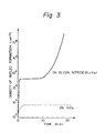
- Fig. 3 is a graph showing the change with lapse of time of nucleation density (ND) on the deposited surface of SiO2 and the deposited surface of silicon nitride.
- the nucleation density (ND) on SiO2 is saturated at l03 cm ⁇ 2 or less, and the value is not substantially changed even after 20 minutes.
- SiCl4 gas is diluted with H2 and deposited according to the CVD method under the conditions of a pressure of l70 Torr and a temperature of l000 °C.
- Such a phenomenon depends greatly on the difference in adsorption coefficient, release coefficient, surface diffusion coefficient, etc., relative to Si of the material surfaces of SiO2 and silicon nitride, but the fact that SiO2 itself is etched by the reaction of SiO2 with Si atom itself to form silicon monooxide with higher vapor pressure, while no such etching phenomenon occurs on silicon nitride may be also considered to be a cause to effect selective deposition (T. Yonehara, S. Yoshioka, S. Miyazawa, Journal of Applied Physics 53, 6839, (l982)).
- nucleation density difference As shown in the same graph, sufficiently great nucleation density difference ( ⁇ ND) as shown in the same graph can be obtained.
- SiO2 is desirable as the material for the deposition surface, this is not limitative and sufficiently practical nucleation density difference ( ⁇ ND) can be obtained even by use of SiO x (0 ⁇ x ⁇ 2).
- nucleation density may be sufficiently l03-fold or more in density of nuclei as shown by the same graph, and sufficient selective formation of deposited film can be done with the materials as exemplified below.
- ions of Si, N, etc. may be injected locally into the SiO2 surface to form a region having excessive Si or N.
- the present invention utilizes selective deposition based on such nucleation density difference ( ⁇ ND) and, by forming a sufficiently minute region of a different kind of material having sufficiently greater nucleation density than the material of the deposition surface, so that a single nucleus may grow on the region, a single crystal is to be grown selectively only at the site where such fine different kind of material exists.
- ⁇ ND nucleation density difference
- the material with higher nucleation density (for example, Si3N4) is not required to be a bulk material, but it may also be formed as a thin film on the surface of base plate of any desired material to form the above crystal formation surface.
- Figs. 4A - 4D are illustrations of the formation steps showing a first embodiment of the method for forming crystal according to the present invention
- Figs. 5A and 5B are perspective views corresponding to Figs. 4A and 4D.
- a thin film 5 non-nucleation surface (S NDS ) with small nucleation density which enables selective deposition is formed and a material different from the material forming the thin film 5 with smaller nucleation density is deposited thinly, followed by patterning according to lithography, etc., to form sufficiently finely nucleation surface 6 (S NDL ) (or called "Seed") comprising a different kind of material.
- S NDL sufficiently finely nucleation surface 6
- the size, the crystal structure and the composition of the substrate 4 may be any desired ones, and a substrate having a functional device formed thereon prepared according to conventional semiconductor technique may be employed.
- the nucleation surface (S NDL ) 6 comprising a different kind of material is also inclusive of modified regions having excessive Si or N formed by ion injection of Si or N into the thin film 5 as described above.
- a crystalline deposited film is formed. That is, a single nucleus of a thin film material is firstly formed only on the nucleation surface (S NDL ) 6.
- the nucleus grows while maintaining a single crystal structure to become a single crystal grain 7 in shape of an island as shown in Fig. 4(B). For forming an island-shaped single crystal grain 7, it is desirable to determine the conditions so that no nucleation may occur at all on the thin film 5, as already mentioned.
- the island-shaped single crystal grain 7 further grows while maintaining the single crystal structure with the nucleation surface (S NDL ) 6 as the center (lateral overgrowth), whereby it can cover over the whole surface of the thin film 5 as shown in the same Figure (C) (single crystal 7A).
- the single crystal 7A is flattened by etching or polishing, and a single crystal layer 8 capable of forming a desired device can be formed on the thin film 5 as shown in Fig. 4(D) and Fig. 5(B).
- any desired material can be used for the substrate 4 which is the supporting member. Further, in such a case, even when the substrate 4 may be one having a functional device, etc., formed thereon according to conventional semiconductor technique, the single crystal layer 8 can be easily formed thereon.
- the non-nucleation surface (S NDS ) is formed of thin film 5, but a substrate comprising a material with small nucleation density (ND) enabling selective nucleation may be used as such and nucleation surfaces (S NDL ) may be provided at any desired positions to form single crystal layers similarly thereon.
- ND nucleation density
- Figs. 6(A) - 6(D) are illustrations of the steps for forming crystal showing a second embodiment of the present invention.
- the nucleation surface (S NDL ) comprising a material with great nucleation density (ND) can be formed sufficiently minutely to form a single crystal layer 8 similarly as in the first embodiment
- Figs. 7(A) - 7(D) are illustrations of the formation steps showing a third embodiment of the method for forming crystal according to the present invention
- Figs. 8(A) and 8(B) are perspective views corresponding to Figs. 7(A) and 7(D).
- nucleation surfaces (S NDL ) 12-1, 12-2, of a material different from the substrate 11 enabling the above selective nucleation are arranged sufficiently finely.
- the distance l is set equal to the size of the single crystal region required for formation of semiconductor device or group of devices or greater.
- the nucleation surfaces (S NDL ) 12-1, 12-2 are required to be formed to a sufficiently fine size (area) to the extent that only a single nucleus may be formed.
- the nucleus grows while maintaining the single crystal structure, and become island-shaped single crystal grains 13-1, 13-2, as shown in Fig. 7(B). For forming island-shaped single crystal grains 13-1, 13-2, it is desirable to determine the conditions so that substantially no nucleation may occur at all on other surfaces than the nucleation surfaces (S NDL ) on the substrate 11.
- the crystal direction in the normal line direction of the substrate 11 of the island-shaped single crystal grains 13-1, 13-2 is determined so as to make the interface energy of the material of the substrate 11 and the material forming nucleus minimum.
- surface or interface energy has anisotropy depending on the crystal face.
- the crystal direction within the substrate plane in amorphous substrate is not determined.
- the island-shaped single crystal grains 13-1, 13-2 further grow to become single crystals 13A-1, 13A-2, until the adjacent single crystals 13A-1, 13A-2, contact each other as shown in Fig. 7(C), but since the crystal directions within the substrate plane are not constant, a crystal grain boundary 14 is formed at the intermediate position between the nucleation surfaces (S NDL ) 12-1 and 12-2.
- the single crystals 13A-1, 13A-2 grow three-dimensionally, but crystal faces with slow growth speed appear as the facet.
- the surfaces of single crystals 13A-1, 13A-2 are flattened by etching or polishing, and further the portion of the grain boundary 14 is removed to form thin films of single crystals 15-1, 15-2,... containing no grain boundary in shape of lattices as shown in Fig. 7(D) and Fig. 8(B).
- the size of the single crystal films 15-1, 15-2, ... is determined by the interval 1 between the nucleation surfaces (S NDL ) 12A-1, 12A-2, as described above. That is, by determining appropriately the formation pattern of the nucleation surface (S NDL ) 12A-1, 12A-2, the position of the grain boundary can be controlled to form single crystals with desired sizes at a desired arrangement
- Fig. 9(A)-(D) are illustrations of the formation steps of crystal showing a fourth embodiment of the present invention.
- a thin film non-nucleation surface (S NDS )5 comprising a material with small nucleation density (ND) enabling selective nucleation is formed
- nucleation surfaces (S NDL )12 comprising a different kind of material with greater nucleation density (ND) are formed with an interval l thereon, and a single crystal layer 15 can be formed in the same manner as in the above third embodiment.
- Figs. 10(A) - 10(C) are illustrations of the formation steps showing a fifth embodiment of the method for forming crystal according to the present invention
- Figs. 11(A) and 11(B) are perspective views of the substrates in Figs. 10(A) and 10(C).
- concavities 16 with desired size and shape are formed on the amorphous insulating substrate 11, and nucleation surfaces (S NDL ) 12 with sufficiently fine size for forming only single nucleus are formed therein.
- island-shaped single crystal grains 13 are grown similarly as in the first embodiment.
- single crystal grains 13 are grown until embedding the concavity 16 to form a single crystal layer 17.
- Fig. 12(A)-(C) are illustrations of the formation steps of crystal showing a sixth embodiment of the present invention.
- a thin film non-nucleation surface (S NDS ) 18 comprising a material with small nucleation density(ND) enabling selective nucleation is formed, and concavities 16 with desired size and shape are formed thereon. and, within the concavities are formed minutely nucleation surfaces (S NDL )12 comprising a material with greater nucleation density (ND) which is different from the material forming the nonnucleation surface (S NDS ), and single crystal layers 17 are formed in the same manner as in the fifth embodiment.
- S NDL minutely nucleation surfaces
- Fig. 13(A)-(C) are illustrations of the formation steps of crystal showing a seventh embodiment of the present invention.
- a thin film nonnucleation surface (S NDS )20 comprising a material with sufficiently small nucleation density (ND) enabling selective nucleation is formed, and following the same procedure as in the above embodiments, single crystal layers 17 can be formed.
- S NDS thin film nonnucleation surface
- ND nucleation density
- Fig. 14 is a schematic sectional view showing an example of the semiconductor electronic device with a multi-layer structure produced by use of the first embodiment of the present invention.
- Fig. 14 on the semiconductor substrate 1401 such as Si or GaAs, transistors 1402 or other semiconductor devices or optical devices are formed, and SiO2 layer 1403 having a surface for formation of, for example, nonnucleation surface (S NDS ) 1404 is formed thereon according to the CVD method or the sputtering method. And, as already mentioned, a thin film 1406 having nucleation surfaces (S NDL ) 1405 having sufficiently minute areas so that only a single nucleus are formed of, for example, Si3N4, and a single crystal is grown from said nucleation surface (S NDL ) 1405 to form an Si single crystal layer 1407.
- S NDS nonnucleation surface
- transistors 1408 or other semiconductor devices or optical devices are formed on the single crystal layer 1407 .
- the devices formed respectively on the substrate 1401 and the Si single crystal layer 1407 are electrically connected through the SiO2 layer 1403.
- transistor 1402 of the first layer (substrate 1401) and the transistor 1408 of the second layer (single crystal layer 1404) respectively as the MOS transistors and connecting these to form CMOS, a CMOS entirely free from mutual interaction can be produced.
- an electroluminescent device can be also formed integrated with its driving circuit to accomplish a high degree of integration.
- single crystal layers 1407 can be formed in many layers with SiO2 layer 1403 sandwiched therebetween, whereby a semiconductor electronic device with a multiple structure can be formed easily.
- Figs. 15(A)-15(D) are illustrations of the steps for forming crystal showing an eighth embodiment of the present invention.
- Figs. 15(A)-15(C) are the same as Figs. 7(A) - 7(C). That is, a plurality (two in the figure) of nucleation surfaces 12 are formed with an interval of l , and single crystal grains 13 subjected to overgrowth on the nucleation surfaces 12 are formed. By permitting the single crystal grains 13 to further grow to form single crystals 13A, a grain boundary 14 is formed approximately at the center between the nucleation surfaces (S NDL ) 12, and by flattening the surface of single crystal 13A, a polycrystalline layer 21 with regular grain sizes which are approximately equal to l as shown in Fig. 15(D) can be obtained.
- the grain size of the polycrystalline layer 21 is determined by the interval l between the nucleation surfaces (S NDL ) 12, it becomes possible to control the grain size of the polycrystal.
- the grain size of a polycrystal was changed by a plural number of factors such as the formation method, formation temperature, etc., and also when preparing a polycrystal with large grain size, it had a grain size distribution with a considerable width.
- the grain size and grain size distribution can be determined with good controllability by the interval l between the nucleation surfaces 12.
- the above polycrystal layer 21 may be formed by forming a non-nucleation surface (S NDS ) 5 with small nucleation density (ND) on a desired substrate 4 and nucleation surfaces (S NDL ) 12-1, 12-2 with greater nucleation density (ND).
- S NDS non-nucleation surface
- S NDL nucleation surfaces
- ND nucleation density
- the substrate material and structure are not limited, but the polycrystal layer 21 can be formed by controlling the grain size and the grain size distribution.
- non-nucleation surface a quartz substrate which is a material with small nucleation density (ND) can be also used as the substrate 11, or alternatively non-nucleation surface (S NDS ) may be provided by forming SiO2 layer on the surface of any desired base substrate such as metal, semiconductor, magnetic material, piezoelectric material, insulator, etc., by use of the sputtering method, the CVD method, the vacuum vapor deposition method, etc.
- SiO2 is desirable, but SiO x (0 ⁇ x ⁇ 1) with the value of x being varied may be also employed.
- silicon nitride layer e.g. Si3N4 layer
- a polycrystalline silicon layer e.g. Si3N4 layer
- S NDL nucleation surface
- the substrate temperature, pressure, etc. may be conveniently determined, but the substrate temperature may be preferably 100 to 600 °C.
- grains 13 of single crystals of Si grow on the nucleation surfaces (S NDS ) 12 comprising silicon nitride layer or polycrystalline silicon layer on the SiO2 layer as the center, and grow to sizes of some 10 ⁇ m or more.
- the surfaces of the single crystals 13A are flattened by selective etching of only Si, whereby a polycrystalline silicon layer 21 controlled in grain size can be formed (Fig. 15(D)). Further, by removing the grain boundary portion, island-shaped single crystalline silicon layers 15-1, 15-2 are formed (Fig. 7(D)). If unevenness on the surface of the single crystal grains 13A-1, 13A-2 are large, mechanical polishing may be conducted before etching.
- RIE reactive ion etching
- C-MOS complementary type electrical field effect transistor
- the thickness of the active layer of the device formed is thinner than the case when employing Si wafer, there is no erroneous actuation by the charges generated when radiation is irradiated. Further, due to lowering in unwanted capacity, speed-up of the device can be effected. Also, since any desired substrate can be used, a single crystal layer can be formed on a substrate of large area at lower cost than when employing Si wafer. Further, since a single crystal layer can be formed also on other semiconductors, piezoelectric materials, dielectric materials, etc., a multi-functional three-dimensional integrated circuit can be realized. Thus, the present invention exhibits a number of excellent effects.
- the material for formation of nucleation surface (S NDL ) is not limited to Si3N4, but silicon nitrides with various chemical composition ratios may be employed.
- the chemical composition ratio of silicon nitride may be varied e.g. as follows.
- the composition ratio of Si and N in the deposited silicon nitride film can be varied to a great extent.
- Fig. 16 is a graph showing an example of the relationship between the flow rate ratio of SiH4 and NH3 and the composition ratio of Si and N in the silicon nitride film formed.
- the deposition conditions at this time were RF output of 175 W, substrate temperature of 380 °C and the flow rate of NH3 gas was varied with the SiH4 gas flow rate being fixed at 300 cc/min.
- the Si/N ratio in the silicon nitride film was found to be varied from 1.1 to 0.58 according to Auger's electron spectrophotometry.
- the silicon nitride film formed by heat treatment of Si at about 1200 °C in ammonia or N2 can be obtained with a composition further approximate to the stoichiometric ratio, since the formation method is performed under thermal equilibrium.
- the above nucleus of Si can be grown on the nucleation surface (S NDL ) comprising silicon nitride to form Si single crystal based on the nucleation density ( ⁇ ND) corresponding to the chemical composition ratio of silicon nitride.
- Fig. 17 is a graph showing the relationship between Si/N composition ratio and nucleation density (ND). As shown in the same graph, by varying the chemical composition ratio of the silicon nitride film, the nucleation density of the Si single crystal nucleus formed thereon changes to a great extent
- the nucleation conditions in the graph shown in Fig. 17 correspond to the case when Si single crystal nucleus was formed by reacting SiCl4 gas reduced to 175 Torr with H2 at 1000°C. Of course, another graph will be obtained if nucleation conditions such as gas species, pressure, temperature, etc., are changed.
- the phenomenon that the nucleation density thus changes according to the chemical composition ratio of silicon nitride affects the size (area) of the nucleation surface (S NDL ) when employing silicon nitride as the material for forming the nucleation surface (S NDL ) which is formed sufficiently finely to the extent that a single nucleus may be grown. That is, when employing silicon nitride having a composition with great nucleation density (ND) only a single crystal can be formed on the nucleation surface (S NDL ) by forming the nucleation surface (S NDL ) extremely finely as compared with the silicon nitride with relatively smaller nucleation density (ND).
- ND nucleation density
- ND nucleation density
- S NDL size of nucleation surface formed of silicon nitride, etc.
- Si/N ratio in that case is about 0.5. .
- ⁇ ND nucleation density difference
- ion injection of Si, N, P, B, F, Ar, He, C, As, Ga, Ge, etc. may be effected locally onto the SiO2 surface which is a material for forming non-nucleation surface (S NDS ) with smaller nucleation density to form a modified region with a desired size on the surface of the SiO2 layer, and utilize this modified region as the nucleation surface (S NDL ) with greater nucleation density (ND).
- S NDS non-nucleation surface
- the SiO2 layer surface is covered with a photoresist layer and the desired portions are exposed, developed, and dissolved to have the SiO2 layer surface exposed.
- SiF4 gas as the source gas, Si ions are implanted onto the SiO2 layer surface portion exposed at 10 keV at a density of 1 ⁇ 1016 - 1 ⁇ 10 18 cm ⁇ 2.
- the projected flying distance in this case is 114 ⁇ , and the Si concentration on the exposed surface of SiO2 layer reaches about 1022 cm ⁇ 3. Since the SiO2 layer is originally amorphous, the modified region made excessively enriched in Si by injection of Si ions is also amorphous.
- ion injection can be effected with the use of a resist as the mask, but it is also possible to inject a narrowed Si ion beam selectively at a desired position on the SiO2 layer surface within a desired area without use of a resist mark by use of converged ion beam technique.
- Si excessive modified region is formed in the SiO2 layer surface portion at a desired position with a desired size.
- Si single crystal is permitted to grow in vapor phase.
- Fig. 18 is a graph showing the relationship between the injected amount of Si ions and the nucleation density (ND).
- nucleation density is increased as the Si+ injected amount is more.
- this modified region sufficiently finely, only single nucleus of Si can be permitted to grow with this modified region as the nucleation surface (S NDL ), whereby a single crystal can be grown as described above.
- Formation of the modified region to a sufficiently fine size to the extent for growth of only a single nucleus can be accomplished easily by patterning of a resist, or narrowing of the beam of converged ion beam.
- Figs. 19(A) - 19(D) are illustrations of the formation steps showing a 9th embodiment of the method for forming crystal according to the present invention
- Figs. 20(A) and 20(B) are perspective views corresponding to Figs. 19(A) and 19(D).
- a thin film 6 [ forming nucleation surface (S NDL )6A ] with greater nucleation density enabling selective nucleation, on which a material different from the material forming the thin film 6 with greater nucleation density is thinly deposited, followed by patterning according to lithography, etc., to form a thin film 5 comprising a different material and forming nonnucleation surface (S NDS )5A so as to provide sufficiently finely nucleation surfaces (S NDL )6A.
- S NDS nonnucleation surface
- the size, the crystal structure, and composition of the base substrate 4 may be chosen as desired, and it may be also a substrate having a functional device prepared according to conventional semiconductor technique formed thereon.
- the nucleation surface (S NDL )6A comprising a different material may be also formed as a modified region containing excessive Si, N or the like which may be formed by forming a thin film 6 beneath the SiO2 thin film 5 of a polycrystalline silicon or SiO2, and injecting ions of Si, N or the like into the exposed portions 6A.
- a single nucleus of a crystal formation material is formed only on the nucleation surface (S NDL )6A. That is, the nucleation surface (S NDL )6A is required to be formed sufficiently minutely so that only a single nucleus may be formed thereon.
- the size of the nucleation surface (S NDL )6A which may differ depending on the kind of the material, may be several microns or less.
- the nucleus grows while maintaining a single crystal structure to become a single crystal grain 7 in shape of an island as shown in Fig. 19(B). For forming an island-shaped single crystal grain 7, it is desirable to determine the conditions so that no nucleation may occur at all on the thin film 5A, as already mentioned.
- the island-shaped single crystal grain 7 further grows while maintaining the single crystal structure with the nucleation surface (S NDL )6A as the center (lateral over growth), whereby it can cover over the whole surface of the thin film 5 as shown in Fig. 19(C) (single crystal 7A).
- the single crystal 7a is flattened by etching or polishing, and a single crystal layer 8 capable of forming a desired device can be formed on the thin film 5 as shown in Fig. 19(D) and Fig. 20(B).
- any desired material can be used for the substrate 4 which is the supporting member. Further, in such a case, even when the substrate 4 may be one having a functional device etc., formed thereon according to conventional semiconductor technique, the single crystal layer 8 can be easily formed thereon.
- the nucleation surface (S NDL )6A is formed of thin film 6, but a substrate comprising a material with large nucleation density (ND) enabling selective nucleation may be used as such and non-nucleation surfaces (S NDS ) may be provided at any desired positions to form single crystal layers similarly thereon as shown in Fig. 21.
- ND nucleation density
- Figs. 21(A) - 21(D) are illustration of the steps for forming crystal showing a second embodiment of the present invention.
- a substrate 9 comprising a material with large nucleation density (ND) enabling selective nucleation
- a thin film 5 forming the non-nucleation surface (S NDS )5A which comprises a material with small nucleation density (ND) can be formed so as to give exposed portions of the substrate 9 as nucleation surface (S NDL )9A sufficiently minutely to form a single crystal layer 8 by the use of said substrate similarly as in the first embodiment.
- Figs. 22(A) - 22(D) are illustrations of the formation steps showing a 11th embodiment of the method for forming crystal according to the present invention
- Figs. 23(A) and 23(B) are perspective views corresponding to Figs. 22(A) and 22(D).
- an amorphous insulating thin film 12 with relatively greater nucleation density (ND) such as Si3N4, etc.
- ND nucleation density
- on said thin film 12 is formed selectively a thin film 11 at a desired position with a different material having smaller nucleation density relative to the material forming the thin film 12 which enables the above selective nucleation with an interval of a distance l , thereby arranging nucleation surfaces (S NDL )12A-1, 12A-2 with sufficiently small areas so as to form only single nucleus thereon.
- This distance l may be set at a size which is equal to or greater than the size of the single crystal region required for formation of a semiconductor device or a group of devices.
- the nucleation surfaces (S NDL )12A-1, 12A-2 are required to be formed to a sufficiently fine size (area) to the extent that only a single nucleus may be formed.
- the size of the nucleation surfaces (S NDL )12A-1, 12A-2 which may be different depending on the kind of the material, may be several microns or less. Further, the nucleus formed as above grows while maintaining the single crystal structure, and become island-shaped single crystal grains 13-1, 13-2 as shown in Fig. 22(B).
- island-shaped single crystal grains 13-1, 13-2 it is desirable to determine the conditions so that substantially no nucleation may occur at all on other surfaces than the nucleation surfaces (S NDL )12A-1, 12A-2 [ non-nucleation surface (S NDS )11A ].
- the crystal direction in the normal line d direction of the thin film 12 of the island-shaped single crystal grains 13-1, 13-2 is determined so as to make the interface energy of the material of the film 12 and the material forming nucleus minimum.
- surface or interface energy has anisotropy depending on the crystal face.
- the crystal direction within the surface plane in amorphous surface is not determined.
- the island-shaped single crystal grains 13-1, 13-2 further grow to become single crystals 13A-1, 13A-2 until the adjacent single crystals 13A-1, 13A-2 contact each other as shown in Fig. 22(C), but since the crystal directions within the substrate plane vary from one single crystal to another, a crystal grain boundary 14 is formed at the intermediate position between the nucleation surfaces (S NDL ) 12-1 and 12-2.
- the single crystals 13A-1, 13A-2 grow three-dimensionally, but crystal faces with slow growth speed appear as the facet. For this reason, the surfaces of single crystals 13A-1, 13A-2 are flattened by etching or polishing, and further the portion of the grain boundary 14 is removed to form thin films of single crystals 15-1, 15-2, ... containing no grain boundary in shape of lattices as shown in Fig. 22(D) and Fig. 23(B).
- the size of the single crystal films 15-1, 15-2, ... is determined by the interval 1 between the nucleation surfaces (S NDL )12A-1, 12A-2 as described above. That is, by determining appropriately the formation pattern of the nucleation surface (S NDL ) 12A-1, 12A-2, the position of the grain boundary can be controlled to form single crystal with desired sizes at a desired arrangement.
- Figs. 24(A) - 24(C) are illustrations of the formation steps showing a 12th embodiment of the method for forming crystal according to the present invention
- Figs. 25(A) and 24(B) are perspective views of the substrates in Figs. 24(A) and 24(C).
- thin film 12 and 11 are provided on the base substrate 10 to form nucleation surfaces (S NDL )12A-1, 12A-2 and non-nucleation surface (S NDS )11A.
- S NDL nucleation surfaces
- S NDS non-nucleation surface
- a thin film 11-1 is formed with same material as the thin film 11a or a material having nucleation density equal to or smaller than said material.
- a substrate for formation of crystal having nucleation surfaces (S NDL )12A-1, 12A-2 with sufficiently fine sizes for forming only single nucleus within concavities 14-1, 14-2 is formded.
- island-shaped single crystal grains 13-1, 13-2 are grown similarly as in the first embodiment.
- single crystal grains 13-1, 13-2 are grown until embedding the concavity 14-1, 14-2 to form a single crystal layer 15-1, 15-2.
- Figs. 26(A) - 26(D) are illustrations of the steps for forming crystal showing a 13th embodiment of the present invention.
- Figs. 26(A) - 26(C) are the same as Figs. 22(A) - 22(C). That is, a plurality (two in the Figure) of nucleation surfaces 12A-1, 12A-2 are formed with an interval of l , and single crystal grains 13-1, 13-2 subjected to over growth on the nucleation surfaces 12A-1, 12A-2 are formed.
- a grain boundary 14 is formed approximately at the center between the non-nucleation surfaces (S NDS )11A, and by flattening the surface of single crystal 13A-1, 13A-2, a polycrystalline layer 16 with regular grain sizes which are approximately equal to l as shown in Fig. 12(D) can be obtained.
- the grain size of the polycrystalline layer 16 is determined by the interval l between the nucleation surfaces (S NDL ) 12A-1, 12A-2, it becomes possible to control the grain size of the polycrystal.
- the grain size of a polycrystal was changed by a plural number of factors such as the formation method, formation temperature, etc., and also when preparing a polycrystal with large grain size, it had a grain size distribution with a considerable width.
- the grain size and grain size distribution can be determined with good controllability by the interval l between the nucleation surfaces (S NDL )12A-1, 12A-2.
- a polycrystal layer may be formed as above by forming a thin film 5 having a non-nucleation surface (S NDS )5A with small nucleation density (ND) on a desired substrate 9 and plural nucleation surfaces (S NDL )9A with greater nucleation density (ND) at desired positions and intervals.
- the substrate material and structure are not limited, provided that the nucleation density difference ( ⁇ ND) is taken into consideration, but the polycrystal layer can be formed by controlling the grain size and the grain size distribution.
- Fig. 27 is a partial sectional view showing schematic construction of an example of the device for forming deposited film in which the process of the present invention is practiced.
- 101 is a deposition chamber (film forming space) in which deposition of silicon thin film is effected, and the deposition chamber 101 is internally connected to an evacuation system not shown through an evacuation outlet 106, whereby the deposition chamber 101 can be maintained at a desired pressure.
- the introducing pipe 102 for radicals (SX) containing e.g., silicon and a halogen which is the active species (A)
- the introducing pipe 103 for e.g., hydrogen radicals as active species (B) respectively.
- the tips of the respective radical introducing pipes are thick at the acting chambers 108, 108A, and narrowed at the outlets 109, 109A.
- a substrate supporting member 104 is held by the roller 110 so as to be movable reciprocally in the direction perpendicular to the paper surface. And on said supporting member 104 is held a support 105 for deposition.
- the respective radicals coming out from the outlet 109, 109A are mixed and reacted with each other in the vicinity of the substrate within the deposition chamber 101 to form a film on the substrate 105.
- the radicals (SX) and hydrogen radicals are formed from the respective starting material gases in the active species forming chambers such as heating furnaces or plasma chambers, etc., not shown, respectively, and thereafter introduced through the introducing pipes 102, 103, respectively into the acting chambers 108, 108A. Their amounts are controlled by massflow controllers on the gas source side from the heating furnace or plasma chamber.
- Roller 110 is provided only for depositing silicon thin film over the whole surface of the substrate by moving the substrate 105.
- the introducing pipe 111 is an introducing pipe for another gas having chemical or physical etching activity (etching gas), and in some cases the etching gas is previously activated in the heating furnace or plasma furnace not shown and led to the outlet 114. From the outlet 114, the etching gas for attacking the film is released to cut or exclude selectively the bonds except in the growth direction of the characteristics of the film.
- Introduction of the etching gas, other than through such separate introduction pipes, can be also done through the introduction pipes 102, 103 mixed with a starting gases, when the reactivity with the starting gases is low.
- a deposited film according to the method of the present invention was prepared as described below.
- the substrate 118 was prepared according to the steps shown in Fig. 28. First, a polycrystalline silicon substrate 201 as shown in Fig. 28(A) was washed and then a thin silicon oxide film 202 was deposited on the whole surface of the substrate 201 according to the sputtering method (in this case, other than the sputtering method, various thin film deposition method, MBE method, CVD method, etc., may be employed). [Fig. 28(B)].
- the sputtering method in this case, other than the sputtering method, various thin film deposition method, MBE method, CVD method, etc., may be employed.
- an electron beam resist layer 203 was applied on the thin film 202 [-Fig. 28(C)], and the electron beam resist layer 203 was exposed to light by use of a photomask with a desired pattern, and the electron beam resist layer 203 was partially removed by development [Fig. 28(D)].
- the silicon oxide thin film 202 was etched to form a thin film 202A having a desired pattern [Fig. 28(E)].
- the regions of the silicon crystals exposed on the surface of the substrate 118 has a diameter of 3 ⁇ m and an interval of 15 ⁇ m.
- Si2F6 as the starting gas for formation of radicals containing silicon and halogen, it was permitted to flow at a flow rate of 100 SCCM into the reaction furnace maintained at 800 °C to be decomposed therein, followed by release through the introducing pipe 102 into the acting chamber 108.
- Ar gas was permitted to flow through the introducing pipe 111 at a rate of 150 SCCM, and a microwave of 2.45 GHz was introduced at a power of 1.0 w/cm2 into said introducing pipe 103 to effect discharging and decompose H2, followed by release of the decomposed gas into the activating chamber 108 at a flow rate of 25 SCCM.
- the substrate temperature was maintained at 330 °C and the pressure at 0.2 Torr.
- Fig. 28(F) shows schematically the crosssection of the crystalline silicon deposited film 205 obtained on the substrate 118.
- the size of the crystal grain 204 was determined so that the crystal grain bounderies 205 became equidistant from the exposed portions 201A of the crystal substrate 201 at which the silicon oxide layer 202 was removed.
- the smoothness was found to be good without wavy pattern, etc., and the film thickness irregularity was ⁇ 4% or less.
- the mobility and electroconductivity of the crystalline Si deposited film of the sample prepared were measured according to the Van der Pauw method, they were found to be 300 (cm/V ⁇ sec) and 9 ⁇ 10 ⁇ 6 (S ⁇ cm ⁇ 1), respectively.
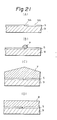
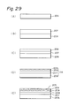
- the substrate 118 was prepared according to the steps shown in Fig. 29.
- a glass substrate 201 comprising substantially uniform composition material as shown in Fig. 29(A) was washed and then according to the thermal CVD method amorphous SiN(A-SiN) thin film 202 was formed with a thickness of about 2 ⁇ m on the whole surface of the substrate 201 [Fig. 29(B)].
- the laser was irradiated with Ar-CW laser of 4880 ⁇ , at a scanning speed of 2.5 cm/sec and at an energy of 10 W. Subsequently, the surface of the C-Si layer 203 was scanned by means of the above laser annealing device in O2 atmosphere to form selectively the SiO2 layer 204 [Fig. 29(D)].
- the substrate 118 having C-Si3N4 layer 203A exposed at constant intervals with other portions being covered with SiO2 layer 204 was formed.
- the domains of C-Si3N4 layer 203A exposed on the substrate surface were about 4 ⁇ m in diameter with intervals of 3 ⁇ m.
- crystalline silicon was deposited by means of the device shown in Fig. 27 similarly as described in Example 1. Deposition conditions were the same as in Example 1 except that the pressure was set at 0.1 Torr and the substrate temperature at 270°C.
- Fig. 29(E) is a schematic drawing showing the cross-section of the crystalline silicon deposited film 205 obtained on the substrate 118.
- the size of the crystal grain was determined so that the crystal grain boundary 206 was at the same distance from the exposed portions 203A of the crystalline substrate 201 other than the SiO2 layer 204.
- the smoothness was found to be good without wavy pattern, etc., and the film thickness irregularity was ⁇ 4% or less.
- the mobility and electroconductivity of the crystalline Si deposited film of the sample prepared were measured according to the Van der Pauw method, they were found to be 150 (cm/V ⁇ sec) and 5 ⁇ 10 ⁇ 6 (S ⁇ cm ⁇ 1), respectively.
- TFT thin film transistor
- an n+ layer (specific resistivity ⁇ ⁇ 1 ⁇ cm) which is the ohmic contact layer 3103 doped with P was formed to a thickness of 1000 ⁇ , and then an active layer 3102 was remained by photolithography, followed by etching of the channel portion 3106 to form the above contact layer 3103. Then, by use of the glow discharge method, NH3 and SiH4 were decomposed to deposit a Si-N-H film with a film thickness of 3000 ⁇ , dielectric constant of 67 and a dielectric strength 3 ⁇ 106 V/cm, V FB ⁇ OV at a substrate temperature of 200 °C.
- the TFT by use of the film as obtained above was found to have good characteristics.
- the method for forming deposited film of the present invention can form a deposited film only by contacting an activated species (A) with an activated species (B), and has the advantage of requiring particularly no reaction exciting energy from the outside. Accordingly, it becomes possible to lower the substrate temperature. Also, since a material which becomes the crystal nucleus for the deposited film or capable of forming selectively the crystal nucleus can be arranged at a desired position on the substrate surface, any desired polycrystalline or single crystalline deposited film with extremely high orientation and great grain size can be formed. Further, simultaneously with saving of energy, it is possible to obtain a crystalline deposited film having uniform film quality and characteristics over a large area with easy management of the film quality. Further, a crystalline film excellent in productivity, bulk productivity and having high quality with excellent electrical, optical semiconductive and other physical properties can be obtained with ease.
Landscapes
- Chemical & Material Sciences (AREA)
- Metallurgy (AREA)
- Chemical Kinetics & Catalysis (AREA)
- Engineering & Computer Science (AREA)
- Materials Engineering (AREA)
- General Chemical & Material Sciences (AREA)
- Organic Chemistry (AREA)
- Mechanical Engineering (AREA)
- Inorganic Chemistry (AREA)
- Crystallography & Structural Chemistry (AREA)
- Crystals, And After-Treatments Of Crystals (AREA)
- Laminated Bodies (AREA)
- Chemical Vapour Deposition (AREA)
- Recrystallisation Techniques (AREA)
- Surface Treatment Of Glass (AREA)
Applications Claiming Priority (4)
| Application Number | Priority Date | Filing Date | Title |
|---|---|---|---|
| JP8393086 | 1986-04-11 | ||
| JP83930/86 | 1986-04-11 | ||
| JP85516/87 | 1987-04-06 | ||
| JP62085516A JP2692804B2 (ja) | 1986-04-11 | 1987-04-06 | 結晶性堆積膜の形成方法 |
Publications (3)
| Publication Number | Publication Date |
|---|---|
| EP0241316A2 true EP0241316A2 (de) | 1987-10-14 |
| EP0241316A3 EP0241316A3 (de) | 1988-09-21 |
| EP0241316B1 EP0241316B1 (de) | 1998-07-22 |
Family
ID=26424966
Family Applications (1)
| Application Number | Title | Priority Date | Filing Date |
|---|---|---|---|
| EP87303224A Expired - Lifetime EP0241316B1 (de) | 1986-04-11 | 1987-04-13 | Verfahren zur Herstellung einer niedergeschlagenen kristalliner Schicht |
Country Status (5)
| Country | Link |
|---|---|
| EP (1) | EP0241316B1 (de) |
| AT (1) | ATE168821T1 (de) |
| AU (2) | AU7143987A (de) |
| CA (1) | CA1329756C (de) |
| DE (1) | DE3752203T2 (de) |
Cited By (8)
| Publication number | Priority date | Publication date | Assignee | Title |
|---|---|---|---|---|
| FR2645178A1 (fr) * | 1989-03-31 | 1990-10-05 | Canon Kk | Procede de formation d'un film cristallin |
| EP0412755A1 (de) * | 1989-08-07 | 1991-02-13 | Canon Kabushiki Kaisha | Verfahren zur Herstellung eines kristallinen Halbleiterfilms |
| EP0472452A1 (de) * | 1990-08-24 | 1992-02-26 | Thomson-Csf | Leistungstransistor und Verfahren zur Herstellung |
| EP0509452A1 (de) * | 1991-04-15 | 1992-10-21 | Canon Kabushiki Kaisha | Lichtemittierende Vorrichtung mit einer stufenförmigen Nichtnukleierungsschicht |
| US5278092A (en) * | 1989-08-07 | 1994-01-11 | Canon Kabushiki Kaisha | Method of forming crystal semiconductor film |
| US5384282A (en) * | 1990-10-29 | 1995-01-24 | Mitsubishi Denki Kabushiki Kaisha | Method for producing an embedded optoelectronic integrated circuit |
| WO2000017423A3 (de) * | 1998-09-21 | 2000-06-22 | Inst Halbleiterphysik Gmbh | Verfahren zur erzeugung einer amorphen oder polykristallinen schicht auf einem isolatorgebiet |
| WO2001090449A1 (en) * | 2000-05-25 | 2001-11-29 | Nanogate Ltd. | A method for growing single crystals |
Family Cites Families (8)
| Publication number | Priority date | Publication date | Assignee | Title |
|---|---|---|---|---|
| US3620833A (en) * | 1966-12-23 | 1971-11-16 | Texas Instruments Inc | Integrated circuit fabrication |
| DE2151346C3 (de) * | 1971-10-15 | 1981-04-09 | Deutsche Itt Industries Gmbh, 7800 Freiburg | Verfahren zum Herstellung einer aus Einkristallschichtteilen und Polykristallschichtteilen bestehenden Halbleiterschicht auf einem Einkristallkörper |
| JPS5767938A (en) * | 1980-10-16 | 1982-04-24 | Canon Inc | Production of photoconductive member |
| JPS6046074B2 (ja) * | 1981-06-30 | 1985-10-14 | 日本電信電話株式会社 | 半導体結晶成長方法 |
| US4443488A (en) * | 1981-10-19 | 1984-04-17 | Spire Corporation | Plasma ion deposition process |
| JPS5969495A (ja) * | 1982-10-13 | 1984-04-19 | Nippon Telegr & Teleph Corp <Ntt> | シリコン単結晶膜の形成方法 |
| JPS6126774A (ja) * | 1984-07-16 | 1986-02-06 | Canon Inc | 非晶質シリコン膜形成装置 |
| US4592792A (en) * | 1985-01-23 | 1986-06-03 | Rca Corporation | Method for forming uniformly thick selective epitaxial silicon |
-
1987
- 1987-04-10 CA CA000534415A patent/CA1329756C/en not_active Expired - Fee Related
- 1987-04-13 AU AU71439/87A patent/AU7143987A/en not_active Abandoned
- 1987-04-13 EP EP87303224A patent/EP0241316B1/de not_active Expired - Lifetime
- 1987-04-13 DE DE3752203T patent/DE3752203T2/de not_active Expired - Fee Related
- 1987-04-13 AT AT87303224T patent/ATE168821T1/de not_active IP Right Cessation
-
1991
- 1991-02-05 AU AU70290/91A patent/AU651806B2/en not_active Ceased
Cited By (12)
| Publication number | Priority date | Publication date | Assignee | Title |
|---|---|---|---|---|
| FR2645178A1 (fr) * | 1989-03-31 | 1990-10-05 | Canon Kk | Procede de formation d'un film cristallin |
| US5213997A (en) * | 1989-03-31 | 1993-05-25 | Canon Kabushiki Kaisha | Method for forming crystalline film employing localized heating of the substrate |
| EP0412755A1 (de) * | 1989-08-07 | 1991-02-13 | Canon Kabushiki Kaisha | Verfahren zur Herstellung eines kristallinen Halbleiterfilms |
| US5278092A (en) * | 1989-08-07 | 1994-01-11 | Canon Kabushiki Kaisha | Method of forming crystal semiconductor film |
| EP0472452A1 (de) * | 1990-08-24 | 1992-02-26 | Thomson-Csf | Leistungstransistor und Verfahren zur Herstellung |
| FR2666172A1 (fr) * | 1990-08-24 | 1992-02-28 | Thomson Csf | Transistor de puissance et procede de realisation. |
| US5273929A (en) * | 1990-08-24 | 1993-12-28 | Thomson-Csf | Method of manufacture transistor having gradient doping during lateral epitaxy |
| US5384282A (en) * | 1990-10-29 | 1995-01-24 | Mitsubishi Denki Kabushiki Kaisha | Method for producing an embedded optoelectronic integrated circuit |
| EP0509452A1 (de) * | 1991-04-15 | 1992-10-21 | Canon Kabushiki Kaisha | Lichtemittierende Vorrichtung mit einer stufenförmigen Nichtnukleierungsschicht |
| US5250819A (en) * | 1991-04-15 | 1993-10-05 | Canon Kabushiki Kaisha | Light emitting device having stepped non-nucleation layer |
| WO2000017423A3 (de) * | 1998-09-21 | 2000-06-22 | Inst Halbleiterphysik Gmbh | Verfahren zur erzeugung einer amorphen oder polykristallinen schicht auf einem isolatorgebiet |
| WO2001090449A1 (en) * | 2000-05-25 | 2001-11-29 | Nanogate Ltd. | A method for growing single crystals |
Also Published As
| Publication number | Publication date |
|---|---|
| EP0241316B1 (de) | 1998-07-22 |
| CA1329756C (en) | 1994-05-24 |
| AU651806B2 (en) | 1994-08-04 |
| ATE168821T1 (de) | 1998-08-15 |
| AU7029091A (en) | 1991-04-18 |
| DE3752203T2 (de) | 1998-12-24 |
| EP0241316A3 (de) | 1988-09-21 |
| AU7143987A (en) | 1987-10-15 |
| DE3752203D1 (de) | 1998-08-27 |
Similar Documents
| Publication | Publication Date | Title |
|---|---|---|
| EP0244081B1 (de) | Verfahren zur Herstellung eines Kristalls und Kristallkörper, die nach diesem Verfahren hergestellt werden | |
| US5846320A (en) | Method for forming crystal and crystal article obtained by said method | |
| US5246886A (en) | Process for depositing a silicon-containing polycrystalline film on a substrate by way of growing Ge-crystalline nucleus | |
| US5254481A (en) | Polycrystalline solar cell manufacturing method | |
| EP0251767A2 (de) | Halbleiterschaltung des isolierten Typs und dessen Herstellungsverfahren | |
| EP0307109A1 (de) | Verfahren zur Herstellung eines Halbleiterkristalls und dabei hergestellter Halbleiterkristall | |
| JP2596547B2 (ja) | 太陽電池及びその製造方法 | |
| AU651568B2 (en) | Method for forming crystalline deposited film | |
| EP0240309B1 (de) | Herstellungsverfahren eines Kristalls und so hergestellter Kristall | |
| EP0241316A2 (de) | Verfahren zur Herstellung einer niedergeschlagenen kristalliner Schicht | |
| US5334864A (en) | Process for selective formation of II-VI group compound film | |
| EP0284435B1 (de) | Selektives Herstellungsverfahren von Schichten aus II-VI-Verbindungen | |
| JP2692804B2 (ja) | 結晶性堆積膜の形成方法 | |
| US5254211A (en) | Method for forming crystals | |
| EP0284434A2 (de) | Verfahren zur Herstellung von Kristallen | |
| US5364815A (en) | Crystal articles and method for forming the same | |
| EP0284441A2 (de) | Kristallisches Verbundprodukt der II-VI-Gruppe und Verfahren zu seiner Herstellung | |
| CA1339827C (en) | Crystal articles and method for forming the same | |
| JP2659746B2 (ja) | ▲ii▼−▲vi▼族化合物結晶物品およびその形成方法 | |
| JP2659745B2 (ja) | ▲iii▼−v族化合物結晶物品およびその形成方法 | |
| EP0289117B1 (de) | Verfahren zur Herstellung von Kristallen auf einem Substrat | |
| JP2592832B2 (ja) | 結晶の形成方法 | |
| JPH01740A (ja) | 2−6族化合物結晶物品およびその形成方法 |
Legal Events
| Date | Code | Title | Description |
|---|---|---|---|
| PUAI | Public reference made under article 153(3) epc to a published international application that has entered the european phase |
Free format text: ORIGINAL CODE: 0009012 |
|
| AK | Designated contracting states |
Kind code of ref document: A2 Designated state(s): AT BE CH DE ES FR GB GR IT LI LU NL SE |
|
| PUAL | Search report despatched |
Free format text: ORIGINAL CODE: 0009013 |
|
| AK | Designated contracting states |
Kind code of ref document: A3 Designated state(s): AT BE CH DE ES FR GB GR IT LI LU NL SE |
|
| 17P | Request for examination filed |
Effective date: 19890215 |
|
| 17Q | First examination report despatched |
Effective date: 19910205 |
|
| GRAG | Despatch of communication of intention to grant |
Free format text: ORIGINAL CODE: EPIDOS AGRA |
|
| GRAG | Despatch of communication of intention to grant |
Free format text: ORIGINAL CODE: EPIDOS AGRA |
|
| GRAH | Despatch of communication of intention to grant a patent |
Free format text: ORIGINAL CODE: EPIDOS IGRA |
|
| GRAH | Despatch of communication of intention to grant a patent |
Free format text: ORIGINAL CODE: EPIDOS IGRA |
|
| GRAA | (expected) grant |
Free format text: ORIGINAL CODE: 0009210 |
|
| AK | Designated contracting states |
Kind code of ref document: B1 Designated state(s): AT BE CH DE ES FR GB GR IT LI LU NL SE |
|
| PG25 | Lapsed in a contracting state [announced via postgrant information from national office to epo] |
Ref country code: AT Free format text: LAPSE BECAUSE OF FAILURE TO SUBMIT A TRANSLATION OF THE DESCRIPTION OR TO PAY THE FEE WITHIN THE PRESCRIBED TIME-LIMIT Effective date: 19980722 Ref country code: BE Free format text: LAPSE BECAUSE OF FAILURE TO SUBMIT A TRANSLATION OF THE DESCRIPTION OR TO PAY THE FEE WITHIN THE PRESCRIBED TIME-LIMIT Effective date: 19980722 Ref country code: IT Free format text: LAPSE BECAUSE OF FAILURE TO SUBMIT A TRANSLATION OF THE DESCRIPTION OR TO PAY THE FEE WITHIN THE PRE;WARNING: LAPSES OF ITALIAN PATENTS WITH EFFECTIVE DATE BEFORE 2007 MAY HAVE OCCURRED AT ANY TIME BEFORE 2007. THE CORRECT EFFECTIVE DATE MAY BE DIFFERENT FROM THE ONE RECORDED.SCRIBED TIME-LIMIT Effective date: 19980722 Ref country code: NL Free format text: LAPSE BECAUSE OF FAILURE TO SUBMIT A TRANSLATION OF THE DESCRIPTION OR TO PAY THE FEE WITHIN THE PRESCRIBED TIME-LIMIT Effective date: 19980722 Ref country code: CH Free format text: LAPSE BECAUSE OF FAILURE TO SUBMIT A TRANSLATION OF THE DESCRIPTION OR TO PAY THE FEE WITHIN THE PRESCRIBED TIME-LIMIT Effective date: 19980722 Ref country code: GR Free format text: LAPSE BECAUSE OF NON-PAYMENT OF DUE FEES Effective date: 19980722 Ref country code: LI Free format text: LAPSE BECAUSE OF FAILURE TO SUBMIT A TRANSLATION OF THE DESCRIPTION OR TO PAY THE FEE WITHIN THE PRESCRIBED TIME-LIMIT Effective date: 19980722 |
|
| REF | Corresponds to: |
Ref document number: 168821 Country of ref document: AT Date of ref document: 19980815 Kind code of ref document: T |
|
| REG | Reference to a national code |
Ref country code: CH Ref legal event code: EP |
|
| REF | Corresponds to: |
Ref document number: 3752203 Country of ref document: DE Date of ref document: 19980827 |
|
| PG25 | Lapsed in a contracting state [announced via postgrant information from national office to epo] |
Ref country code: SE Free format text: LAPSE BECAUSE OF FAILURE TO SUBMIT A TRANSLATION OF THE DESCRIPTION OR TO PAY THE FEE WITHIN THE PRESCRIBED TIME-LIMIT Effective date: 19981022 |
|
| ET | Fr: translation filed | ||
| NLV1 | Nl: lapsed or annulled due to failure to fulfill the requirements of art. 29p and 29m of the patents act | ||
| PG25 | Lapsed in a contracting state [announced via postgrant information from national office to epo] |
Ref country code: ES Free format text: LAPSE BECAUSE OF FAILURE TO SUBMIT A TRANSLATION OF THE DESCRIPTION OR TO PAY THE FEE WITHIN THE PRESCRIBED TIME-LIMIT Effective date: 19990119 |
|
| REG | Reference to a national code |
Ref country code: CH Ref legal event code: PL |
|
| PG25 | Lapsed in a contracting state [announced via postgrant information from national office to epo] |
Ref country code: LU Free format text: LAPSE BECAUSE OF NON-PAYMENT OF DUE FEES Effective date: 19990413 |
|
| PLBE | No opposition filed within time limit |
Free format text: ORIGINAL CODE: 0009261 |
|
| STAA | Information on the status of an ep patent application or granted ep patent |
Free format text: STATUS: NO OPPOSITION FILED WITHIN TIME LIMIT |
|
| 26N | No opposition filed | ||
| REG | Reference to a national code |
Ref country code: GB Ref legal event code: IF02 |
|
| PGFP | Annual fee paid to national office [announced via postgrant information from national office to epo] |
Ref country code: GB Payment date: 20030331 Year of fee payment: 17 |
|
| PGFP | Annual fee paid to national office [announced via postgrant information from national office to epo] |
Ref country code: FR Payment date: 20030422 Year of fee payment: 17 |
|
| PGFP | Annual fee paid to national office [announced via postgrant information from national office to epo] |
Ref country code: DE Payment date: 20030424 Year of fee payment: 17 |
|
| PG25 | Lapsed in a contracting state [announced via postgrant information from national office to epo] |
Ref country code: GB Free format text: LAPSE BECAUSE OF NON-PAYMENT OF DUE FEES Effective date: 20040413 |
|
| PG25 | Lapsed in a contracting state [announced via postgrant information from national office to epo] |
Ref country code: DE Free format text: LAPSE BECAUSE OF NON-PAYMENT OF DUE FEES Effective date: 20041103 |
|
| GBPC | Gb: european patent ceased through non-payment of renewal fee |
Effective date: 20040413 |
|
| PG25 | Lapsed in a contracting state [announced via postgrant information from national office to epo] |
Ref country code: FR Free format text: LAPSE BECAUSE OF NON-PAYMENT OF DUE FEES Effective date: 20041231 |
|
| REG | Reference to a national code |
Ref country code: FR Ref legal event code: ST |