EP0284435B1 - Selektives Herstellungsverfahren von Schichten aus II-VI-Verbindungen - Google Patents
Selektives Herstellungsverfahren von Schichten aus II-VI-Verbindungen Download PDFInfo
- Publication number
- EP0284435B1 EP0284435B1 EP88302719A EP88302719A EP0284435B1 EP 0284435 B1 EP0284435 B1 EP 0284435B1 EP 88302719 A EP88302719 A EP 88302719A EP 88302719 A EP88302719 A EP 88302719A EP 0284435 B1 EP0284435 B1 EP 0284435B1
- Authority
- EP
- European Patent Office
- Prior art keywords
- film
- group
- compound film
- group compound
- substrate
- Prior art date
- Legal status (The legal status is an assumption and is not a legal conclusion. Google has not performed a legal analysis and makes no representation as to the accuracy of the status listed.)
- Expired - Lifetime
Links
Images


Classifications
-
- H—ELECTRICITY
- H10—SEMICONDUCTOR DEVICES; ELECTRIC SOLID-STATE DEVICES NOT OTHERWISE PROVIDED FOR
- H10D—INORGANIC ELECTRIC SEMICONDUCTOR DEVICES
- H10D86/00—Integrated devices formed in or on insulating or conducting substrates, e.g. formed in silicon-on-insulator [SOI] substrates or on stainless steel or glass substrates
- H10D86/01—Manufacture or treatment
-
- H—ELECTRICITY
- H10—SEMICONDUCTOR DEVICES; ELECTRIC SOLID-STATE DEVICES NOT OTHERWISE PROVIDED FOR
- H10F—INORGANIC SEMICONDUCTOR DEVICES SENSITIVE TO INFRARED RADIATION, LIGHT, ELECTROMAGNETIC RADIATION OF SHORTER WAVELENGTH OR CORPUSCULAR RADIATION
- H10F71/00—Manufacture or treatment of devices covered by this subclass
- H10F71/125—The active layers comprising only Group II-VI materials, e.g. CdS, ZnS or CdTe
- H10F71/1253—The active layers comprising only Group II-VI materials, e.g. CdS, ZnS or CdTe comprising at least three elements, e.g. HgCdTe
-
- H—ELECTRICITY
- H10—SEMICONDUCTOR DEVICES; ELECTRIC SOLID-STATE DEVICES NOT OTHERWISE PROVIDED FOR
- H10F—INORGANIC SEMICONDUCTOR DEVICES SENSITIVE TO INFRARED RADIATION, LIGHT, ELECTROMAGNETIC RADIATION OF SHORTER WAVELENGTH OR CORPUSCULAR RADIATION
- H10F77/00—Constructional details of devices covered by this subclass
- H10F77/10—Semiconductor bodies
- H10F77/12—Active materials
- H10F77/126—Active materials comprising only Group I-III-VI chalcopyrite materials, e.g. CuInSe2, CuGaSe2 or CuInGaSe2 [CIGS]
-
- H10P14/24—
-
- H10P14/271—
-
- H10P14/2921—
-
- H10P14/2922—
-
- H10P14/3238—
-
- H10P14/3428—
-
- H10P14/3431—
-
- H10P14/3436—
-
- Y—GENERAL TAGGING OF NEW TECHNOLOGICAL DEVELOPMENTS; GENERAL TAGGING OF CROSS-SECTIONAL TECHNOLOGIES SPANNING OVER SEVERAL SECTIONS OF THE IPC; TECHNICAL SUBJECTS COVERED BY FORMER USPC CROSS-REFERENCE ART COLLECTIONS [XRACs] AND DIGESTS
- Y02—TECHNOLOGIES OR APPLICATIONS FOR MITIGATION OR ADAPTATION AGAINST CLIMATE CHANGE
- Y02E—REDUCTION OF GREENHOUSE GAS [GHG] EMISSIONS, RELATED TO ENERGY GENERATION, TRANSMISSION OR DISTRIBUTION
- Y02E10/00—Energy generation through renewable energy sources
- Y02E10/50—Photovoltaic [PV] energy
- Y02E10/541—CuInSe2 material PV cells
-
- Y—GENERAL TAGGING OF NEW TECHNOLOGICAL DEVELOPMENTS; GENERAL TAGGING OF CROSS-SECTIONAL TECHNOLOGIES SPANNING OVER SEVERAL SECTIONS OF THE IPC; TECHNICAL SUBJECTS COVERED BY FORMER USPC CROSS-REFERENCE ART COLLECTIONS [XRACs] AND DIGESTS
- Y02—TECHNOLOGIES OR APPLICATIONS FOR MITIGATION OR ADAPTATION AGAINST CLIMATE CHANGE
- Y02E—REDUCTION OF GREENHOUSE GAS [GHG] EMISSIONS, RELATED TO ENERGY GENERATION, TRANSMISSION OR DISTRIBUTION
- Y02E10/00—Energy generation through renewable energy sources
- Y02E10/50—Photovoltaic [PV] energy
- Y02E10/543—Solar cells from Group II-VI materials
Definitions
- This invention relates to a process for selective formation of a deposited film, particularly to a selective formation process for forming a deposited film of a II-VI group compound in a self-alignment fashion.
- the selective formation process of a deposited film according to the present invention is applicable for, for example, preparation of thin films to be used for semiconductor integrated circuits, optical integrated circuits, etc.
- Figs. 1A -1E illustrate the steps of the process of the prior art for forming a thin film by photolithography.
- a substrate 1 comprising a material species with uniform composition as shown in Fig. 1A is washed, and then a thin film 2 is deposited on the whole surface of the substrate 1 according to various thin film depositing methods (vacuum vapor deposition method, sputtering method, plasma discharging method, MBE method, CVD method, etc.) (Fig. 1B).
- various thin film depositing methods vacuum vapor deposition method, sputtering method, plasma discharging method, MBE method, CVD method, etc.
- a photoresist 3 (Fig. 1C), and the photoresist 3 is exposed to light by use of a photomask of a desired pattern and the photoresist 3 is removed partially by development (Fig. 1D).
- the thin film 2 is etched to form a thin film 2 with a desired pattern (Fig. 1E).
- thin films of desired patterns are laminated to constitute an integrated circuit.
- alignment between the thin films of the respective layers becomes an extremely important factor for the characteristics of the device.
- precision of the shape of thin films of the respective layers is also extremely important along with alignment.
- Figs. 2A - 2D illustrate the steps of the process of the prior art for forming a thin film by use of lift-off.
- a photoresist 4 is applied on a substrate 1 (Fig. 2A), and the photoresist 4 with a desired pattern is removed by photolithography (Fig. 2B).
- a thin film 5 is deposited according to a thin film deposition method (Fig. 2C), and the remaining photoresist 4 is dissolved away.
- the thin film on the remaining photoresist 4 is removed at the same time, whereby a thin film 5 with a desired pattern is formed.
- the selective deposition method there has been known the method in which a monocrystal substrate is covered partially with an amorphous thin film, and the same material as the substrate material is epitaxially grown selectively only at the exposed portion of the monocrystal substrate.
- SEG selective epitaxial growth
- a silicon monocrystal substrate is partially covered with silicon oxide to effect selective growth of silicon
- a GaAs substrate is covered partially with an amorphous thin film such as SiO 2 , Si 3 N 4 , etc. to effect selectively epitaxial growth of GaAs
- P. Rai-Choudhury & D.K. Schroder J. Electrochem. Soc., 118, 107, 1971
- the deposited film forming method of the prior art is limited in available substrates, and further there are involved problems also in the shape of the pattern, the dimensional precision of the deposited film formed, etc.
- Example 1 a process of forming a lead tin telluride film as a IV-VI Group compound semiconductor on the surface of a barium fluoride substrate having a (1,1,1) plane as single crystal surface. Areas of the barium fluoride substrate are irradiated by an electron beam and are by this means inhibited from supporting epitaxial growth of the compound semiconductor film. This effect can be erased by a second electron beam irradiation at an elevated temperature.
- the second of these documents discloses the forming of IVA-VIA compound semiconductors on a single crystal metallic oxide substrate such as sapphire ( - Al 2 O 3 ) by an MOCVD technique. There is also disclosed in this document the formation of IVA-VIA compound semiconductor material on a single crystal substrate of II-VI compound semiconductor material.
- An object of the present invention is to solve such problems of the prior art and provide a process for forming a II-VI group compound film with any desired shape in a self-alignment fashion at any desired portion of a substrate, irrespective of the crystallinity of the base substrate.
- a process for selective formation of a polycrystalline II-VI group compound film for a semiconductor or optical integrated circuit which comprises depositing said film from a gas phase by organometallic chemical vapour deposition, molecular beam epitaxy or from a liquid phase by liquid phase epitaxy, the gas phase or the liquid phase including a starting material for supplying group II atoms and a starting material for supplying group VI atoms, over a substrate having a non-nucleation surface of SiO 2 material and having a nucleation surface defined either (a) by a thin film layer of Al 2 O 3 disposed on the surface of SiO 2 material, or (b) by a region of the surface of SiO 2 material in which are implanted ions of an element selected from the groups II, III, V and VI elements of the periodic table, whereby said polycrystalline II-VI compound film is selectively formed only on said nucleation surface.
- Figs. 1A - 1E illustrates the steps showing a thin film forming process according to photolithography of the prior art.
- Figs. 2A - 2D illustrates the steps showing a thin film forming process by use of lift-off of the prior art.
- Fig. 3 is a line diagram showing the relationship between the change ⁇ G in free energy G and the radius of nucleus.
- Figs. 4A - 4D illustrates schematically the process for selective formation of a deposited film according to the present invention.
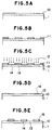
- Figs. 5A - 5E illustrates the steps showing an example of selective formation of a CdSe film.
- Fig. 6A-6F are preparation steps of a CdSe thin film transistor using the process of the present invention.
- Figs. 7A - 7E illustrates the steps showing another example of selective formation of a CdSe film.
- the II-VI group compounds to be used in the present invention are not limited to 2-element compounds, but also include multi-element II-VI group mixed crystal compounds of 3 elements or more.
- the deposited film formation process is considered as follows.
- the substrate having a deposition surface is a material different in kind from the flying atoms, particularly an amorphous material
- the flying atoms will be freely diffused on the substrate surface, or revaporized.
- a nucleus is formed, and when the nucleus reaches the size rc where the change ⁇ G in its free energy G becomes the maximum (stable nucleus) or more, ⁇ G is reduced and the nucleus continues to grow stably three-dimensionally and become shaped in an island.
- the nucleus grows to become shaped in an island, and further grows until contact mutually between islands proceeds to cover the substrate surface in shape of a network, finally covering completely the substrate surface as a continuous film. Through such process, a thin film is deposited on the substrate.
- the density of the nucleus formed per unit area of the substrate surface depends greatly on the interaction between the flying atoms and the substrate, and is also greatly influenced by the deposition conditions, typically the temperature.
- the nucleation density (or nucleation speed) can be determined. Therefore, when one kind of material to be deposited is used and deposit on a deposition surface comprising two or more kinds of surfaces differing greatly in the above nucleation density, the deposited film can be formed selectively depending on the difference on nucleation density. For example, it is formed selectively as described below.
- Figs. 4A - 4D illustrate schematically the process of forming a deposited film according to the present invention.
- the two kinds of materials constituting the deposition surface are called A and B, and the material to be deposited C, and the above materials A, B and C are selected so that the nucleation density of the material to be deposited C for the materials A and B may differ greatly, under certain deposition conditions.
- the nucleation density for the material A is sufficiently great, and the nucleation density for the material B is negligibly small.
- a thin film 6 of the material B is deposited according to a thin film forming method, and ions of the material A are implanted with a desired pattern by use of the converging ion beam implantation technique thereon.
- a region 7 of the material A is formed with a desired pattern so as to have a large area sufficient for a number of nuclei for crystal growth to be generated on the thin film 6 of the material B.
- a mask 8 may be formed with a desired pattern on the material B, and ions of the material A injected on the whole surface to provide the region 7, thereby forming a deposition surface as shown in Fig. 4B.
- a thin film of the material A may be formed on the material B, and the thin film of the material A may be formed to a desired pattern by photolithography.
- the material C is deposited under predetermined conditions. At this time, no material C is deposited on the thin film 6 of the material B.
- This may be considered to be due to revaporization of the flying atoms of the material C before becoming stable nucleus, or due to formation of a substance with high vapor pressure through the reaction of C atoms with the material B, whereby the material B is etched.
- the material C is deposited, and consequently a deposited film 9 with same pattern as the pattern of the region 7 of the material A can be formed in a self-alignment fashion.
- a SiO 2 film 10 was deposited to about 100 nm (1000 ⁇ ) by conventional CVD (chemical vapor deposition) by use of silane (SiH 4 ) and oxygen (O 2 ) [Fig. 5A].
- the nucleation density (NDs) of CdSe on the SiO 2 film is small, and the SiO 2 film 10 becomes the non-nucleation surface (S NDS ).
- Se ions 12 were implanted at a density of 3 x 10 16 /cm 2 .
- the Se ions were implanted only on the surface exposed [Fig. 5C].
- the nucleation density (NDs) of CdSe is small, and this portion becomes the non-nucleation surface (S NDS ) as described above.
- the region 14 where Se ions are implanted has larger nucleation density (ND L ) than the non-nucleation surface (S NDS ), which portion becomes the nucleation surfaces (S NDL ).
- the size of the region 7 was made 1mm x 1mm square.
- the substrate 1 was subjected to heat treatment in a PCl 3 atmosphere at about 450 °C for about 10 minutes to clean the surface [Fig. 5D].
- CdSe film 15 was formed only on the nucleation surface (S NDL ) 14 formed by implantation of Se ions, and no CdSe film was formed on the non-nucleation surface (S NDS ) 13, namely the SiO 2 surface where no Se ion was implanted.
- a CdSe film with any desired shape and dimension can be selectively formed.
- an Al film was deposited on an alumina substrate 1 to about 100 nm (1000 ⁇ ) according to the vacuum vapor deposition method, followed by patterning by conventional photolithographic technique to form a gate electrode 16 [Fig. 6A].
- a SiO 2 film 17 was deposited to about 300 nm (3000 ⁇ ) to give a gate oxide film [Fig. 6B].
- the SiO 2 surface having small nucleation density (NDs) became the non-nucleation surface (S NDS ), and the ion implanted portion having larger nucleation density (ND L ) became the nucleation surface (S NDL ), whereby CdSe 21 was formed selectively only on the nucleation surface (S NDL ) 20.
- the Al film was worked to form the source electrode 23 and the drain electrode 24, thus completing a thin film transistor [Fig. 6F].
- a CdSe film can be formed selectively only on the nucleation surface (S NDL )
- a thin film transitor can be prepared without chemically etching CdSe as different from the prior art method. For this reason, thin film transistors of good quality could be prepared with good yield, as compared with the prior art method.
- Figs. 7A - 7E illustrate the film formation steps of another example of the present invention.
- a SiO 2 film 25 was deposited to about 100 nm (1000 ⁇ ) according to the CVD method by use of SiH 4 and O 2 [Fig. 7A].
- an Al 2 O 3 film was formed on the SiO 2 film 25 by means of an arc discharge type ion plating device.
- the device was internally evacuated to 10 -3 pa (10 -5 Torr)
- O 2 gas was introduced to 4x10 -2 Pa (3 x 10 -4 Torr)
- an Al 2 O 3 film 26 was deposited toabout 30 nm (300 ⁇ ) on the substrate heated to 400 °C at an ionization voltage of 50 V, a substrate potential of -50 V and an output of 500 W [Fig. 7B].
- the substrate 1 was subjected to heat treatment in a PCl 3 atmosphere at about 450 °C for about 10 minutes to clean the surface [Fig. 7D].
- NDs nucleation density
- S NDS non-nucleation surface
- Al 2 O 3 26 has larger nucleation density (ND L ) than the non-nucleation surface (S NDS ) 25, which portion becomes the nucleation surface (S NDL ).
- CdSe film 28 was formed only on the Al 2 O 3 nucleation surfaces (S NDL ) 26, and no CdSe film was formed on the non-nucleation surface (S NDS ) 25, namely the SiO 2 surface.
- the size of the nucleation surface (S NDL ) 26 was made 1 mm x 1 mm square.
- a ZnSSe mixed crystal II - VI group compound film was selectively formed as follows.
- Se ions were implanted into the exposed SiO 2 at 1 x 10 15 /cm 2 by use of an ion implanter.
- the resist film was peeled off, and the substrate 1 was subjected to heat tretment in a PCl 3 atmosphere at about 450 °C for about 10 minutes to clean the surface.
- the SiO 2 film portion implanted with no Se ions has smaller nucleation density (NDs) to become the non-nucleation surface (S NDS ).
- the SiO 2 film portion implanted with Se ions has larger nucleation density (ND L ) to become the nucleation surface (S NDL ).
- the ternary mixed crystal II - VI group compound ZnSSe film was formed selectively.
- the size of the nucleation surface (S NDL ) was made 1 mm x 0.5 mm square.
- the ratio of S and Se in ZnSSe can be freely controlled by varying the ratio of the reactive gases DES and DMSe.
- a chalcopyrite type compound film with the group II element in the II - VI compound substituted with the group I element and the group III element was formed as follows.
- a SiO 2 film was formed on the substrate, and Se ions were partially implanted thereon similarly as in Example 1 to form a nucleation surface (S NDL ).
- an Al 2 O 3 film may be formed on SiO 2 film, followed by patterning to form a nucleation surface (S NDL ).
- a chalcopyrite film was selectively formed according to the MOCVD method only on the fine nucleation surface (S NDL ) on the substrate having the non-nucleation surface (S NDS ) and the nucleation surface (S NDL ).
- cyclopentadienyltriethylphosphine copper [C 5 H 5 CuP(C 2 H 5 ) 3 ], trimethylgallium (TMG) and hydrogen sulfide (H 2 S) were supplied as the reactive gases together with the carrier gas H 2 onto the substrate.
- C 5 H 5 CuP(C 2 H 5 ) 3 and TMG were supplied in equal moles, with the amount of H 2 S being made about several-fold of the sum of the former two.
- the reaction pressure was made 50 Torr, and the substrate temperature 600 °C.
- CuGaS 2 could be formed selectively only on SiO 2 implanted with Se ions..
- a nucleation surface (S NDL ) having a large nucleation density (ND L ) can be formed to a desired pattern and a II - VI group compound semiconductor film following the pattern can be formed.
- the ion species to be implanted for formaton of the nucleation surface is not limited to Se ions, but ions of the group II elements, ions of the group VI elements, further ions of the group III elements and ions of the group V elements can be also used.
- dimethylzinc diethylzinc [Zn(C 2 H 5 ) 2 ], dimethylcadmium [Cd(CH 3 ) 2 ], diethylcadmium, dipropylcadmium [Cd(C 3 H 7 ) 2 ], dibutylcadmium [Cd(C 4 H 9 ) 2 ], dimethylmercury [Hg(CH 3 ) 2 ], diethylmercury [Hg(C 2 H 5 ) 2 ] as the starting gas of the group II element, and hydrogen sulfide (H 2 S), selenium hydride, dimethylselenium, diethylselenium [Se(C 2 H 5 ) 2 ], dimethyldiselenide [CH 3 SeCH 3 ], dimethyltellurium [Te(CH 3 ) 2 ], diethyltellurium [Te(C 2 H 5 ) 2 ] as the starting gas of the group VI element, films of II - VI group compounds Zn
- a mixed crystal compound semiconductor can be formed selectively on Al 2 O 3 provided on the SiO 2 similarly as in Example 2 as the nucleation surface (S NDL ), as a matter of course.
- the process for selective formation of a II-VI group compound film can form self-matchingly a deposited film of a desired pattern by utilizing the nucleation density difference ( ⁇ ND) depending on the kinds of the II-VI group compound deposition surface materials, and therefore a deposited film with a desired pattern can be formed at high precision, which is advantageous particularly in constituting a highly integrated circuit.
- the materials of the deposition surface are not required to be limited to only monocrystal but a II-VI group compound deposited film can be formed at high precision also on an amorphous insulating material by selecting the material for forming nucleation surface (S NDL ) and the material for forming non-nucleation surface (S NDS ) having nucleation density difference.
- a pattern can be formed without etching of the film itself, and therefore it becomes possible to maintain chemical stability of the film prepared at high level.
Claims (4)
- Selektives Bildungsverfahren für eine Schicht aus einer polykristallinen Verbindung, welche aus Atomen der Gruppen II-VI besteht, für einen Halbleiter oder einen integrierten optischen Schaltkreis, umfassend die Abscheidung der Schicht aus einer Gasphase durch organometallische chemische Dampfabscheidung, Molekularstrahlepitaxie oder aus einer flüssigen Phase durch Flüssigphasenepitaxie, wobei die Gasphase oder die flüssige Phase ein Ausgangsmaterial zur Zuführung von Atomen der Gruppe II und ein Ausgangsmaterial zur Zuführung von Atomen der Gruppe VI einschließt, auf ein Substrat mit einer Oberfläche ohne Keimbildung aus SiO2-Material und mit einer Oberfläche mit Keimbildung, welche entweder (a) durch eine auf der Oberfläche aus SiO2-Material angeordneten Dünnfilmschicht aus Al2O3 oder (b) durch einen Bereich der Oberfläche aus SiO2-Material, in welchen Ionen eines aus den Gruppen II, III, V und VI des Periodensystems ausgewählten Elements injiziert sind, definiert ist, wobei die Schicht aus der polykristallinen Verbindung, welche aus Atomen der Gruppen II-VI besteht, selektiv nur auf der Oberfläche mit Keimbildung gebildet wird.
- Selektives Bildungsverfahren für eine Schicht aus einer Verbindung aus Atomen der Gruppen II-VI nach Anspruch 1, wobei die Schicht aus der Verbindung, welche aus Atomen der Gruppen II-VI besteht, eine Schicht aus einer binären Verbindung aus Atomen der Gruppen II-VI ist.
- Selektives Bildungsverfahren für eine Schicht aus einer Verbindung aus Atomen der Gruppen II-VI nach Anspruch 1, wobei die Schicht aus der Verbindung, welche aus Atomen der Gruppen II-VI besteht, eine Schicht aus einer Mehrfachkomponenten-Mischkristallverbindung aus Atomen der Gruppen II-VI ist, welche einem ternären oder höheren System entspricht.
- Selektives Bildungsverfahren für eine Schicht aus einer Verbindung aus Atomen der Gruppen II-VI nach Anspruch 1, wobei in der Verbindung aus Atomen der Gruppen II-VI die Atome der Gruppe II durch Atome der Gruppe I und Atome der Gruppe III ersetzt sind.
Applications Claiming Priority (2)
| Application Number | Priority Date | Filing Date | Title |
|---|---|---|---|
| JP71991/87 | 1987-03-26 | ||
| JP62071991A JPS63237533A (ja) | 1987-03-26 | 1987-03-26 | 2−6族化合物膜の選択形成方法 |
Publications (3)
| Publication Number | Publication Date |
|---|---|
| EP0284435A2 EP0284435A2 (de) | 1988-09-28 |
| EP0284435A3 EP0284435A3 (de) | 1989-01-25 |
| EP0284435B1 true EP0284435B1 (de) | 1997-10-15 |
Family
ID=13476438
Family Applications (1)
| Application Number | Title | Priority Date | Filing Date |
|---|---|---|---|
| EP88302719A Expired - Lifetime EP0284435B1 (de) | 1987-03-26 | 1988-03-25 | Selektives Herstellungsverfahren von Schichten aus II-VI-Verbindungen |
Country Status (5)
| Country | Link |
|---|---|
| US (1) | US5100691A (de) |
| EP (1) | EP0284435B1 (de) |
| JP (1) | JPS63237533A (de) |
| CA (1) | CA1322937C (de) |
| DE (1) | DE3856041T2 (de) |
Families Citing this family (6)
| Publication number | Priority date | Publication date | Assignee | Title |
|---|---|---|---|---|
| GB2183090B (en) * | 1985-10-07 | 1989-09-13 | Canon Kk | Method for selective formation of deposited film |
| US5334864A (en) * | 1987-03-26 | 1994-08-02 | Canon Kabushiki Kaisha | Process for selective formation of II-VI group compound film |
| AU623861B2 (en) * | 1987-08-08 | 1992-05-28 | Canon Kabushiki Kaisha | Crystal article, method for producing the same and semiconductor device utilizing the same |
| JP3553147B2 (ja) * | 1994-09-05 | 2004-08-11 | 三菱電機株式会社 | 半導体層の製造方法 |
| JP4310076B2 (ja) * | 2001-05-31 | 2009-08-05 | キヤノン株式会社 | 結晶性薄膜の製造方法 |
| JP5899606B2 (ja) * | 2010-03-04 | 2016-04-06 | 株式会社リコー | 積層構造体の製造方法 |
Family Cites Families (14)
| Publication number | Priority date | Publication date | Assignee | Title |
|---|---|---|---|---|
| US3697342A (en) * | 1970-12-16 | 1972-10-10 | Ibm | Method of selective chemical vapor deposition |
| DE2151127C3 (de) * | 1970-12-16 | 1981-04-16 | International Business Machines Corp., 10504 Armonk, N.Y. | Verfahren zum Abscheiden eines Metallisierungsmusters und seine Anwendung |
| US4066481A (en) * | 1974-11-11 | 1978-01-03 | Rockwell International Corporation | Metalorganic chemical vapor deposition of IVA-IVA compounds and composite |
| US4216037A (en) * | 1978-01-06 | 1980-08-05 | Takashi Katoda | Method for manufacturing a heterojunction semiconductor device by disappearing intermediate layer |
| US4239788A (en) * | 1979-06-15 | 1980-12-16 | Martin Marietta Corporation | Method for the production of semiconductor devices using electron beam delineation |
| JPS57196542A (en) * | 1981-05-28 | 1982-12-02 | Fujitsu Ltd | Semiconductor integrated circuit device and manufacture thereof |
| US4637127A (en) * | 1981-07-07 | 1987-01-20 | Nippon Electric Co., Ltd. | Method for manufacturing a semiconductor device |
| US4615904A (en) * | 1982-06-01 | 1986-10-07 | Massachusetts Institute Of Technology | Maskless growth of patterned films |
| JPS59167028A (ja) * | 1983-03-11 | 1984-09-20 | Mitsubishi Electric Corp | 化合物半導体集積回路装置の製造方法 |
| US4467521A (en) * | 1983-08-15 | 1984-08-28 | Sperry Corporation | Selective epitaxial growth of gallium arsenide with selective orientation |
| US4557037A (en) * | 1984-10-31 | 1985-12-10 | Mobil Solar Energy Corporation | Method of fabricating solar cells |
| JPH0682621B2 (ja) * | 1985-06-10 | 1994-10-19 | 古河電気工業株式会社 | GaAsの選択エピタキシヤル成長方法 |
| JPS6262581A (ja) * | 1985-09-12 | 1987-03-19 | Furukawa Electric Co Ltd:The | 半導体発光装置の製造方法 |
| JPH0782996B2 (ja) * | 1986-03-28 | 1995-09-06 | キヤノン株式会社 | 結晶の形成方法 |
-
1987
- 1987-03-26 JP JP62071991A patent/JPS63237533A/ja active Pending
-
1988
- 1988-03-25 CA CA000562512A patent/CA1322937C/en not_active Expired - Fee Related
- 1988-03-25 DE DE3856041T patent/DE3856041T2/de not_active Expired - Fee Related
- 1988-03-25 EP EP88302719A patent/EP0284435B1/de not_active Expired - Lifetime
-
1991
- 1991-04-16 US US07/686,868 patent/US5100691A/en not_active Expired - Lifetime
Non-Patent Citations (2)
| Title |
|---|
| J. Electrochem. Soc.: Solid State Science, vol. 118, no. 1, January 1971, pp. 107-110 * |
| Philips Technical Review, vol. 41, no.2, 1983/84, pp. 239-243 * |
Also Published As
| Publication number | Publication date |
|---|---|
| DE3856041D1 (de) | 1997-11-20 |
| JPS63237533A (ja) | 1988-10-04 |
| DE3856041T2 (de) | 1998-03-12 |
| EP0284435A2 (de) | 1988-09-28 |
| US5100691A (en) | 1992-03-31 |
| CA1322937C (en) | 1993-10-12 |
| EP0284435A3 (de) | 1989-01-25 |
Similar Documents
| Publication | Publication Date | Title |
|---|---|---|
| US5010033A (en) | Process for producing compound semiconductor using an amorphous nucleation site | |
| US5281283A (en) | Group III-V compound crystal article using selective epitaxial growth | |
| EP0251767A2 (de) | Halbleiterschaltung des isolierten Typs und dessen Herstellungsverfahren | |
| EP0284435B1 (de) | Selektives Herstellungsverfahren von Schichten aus II-VI-Verbindungen | |
| US5334864A (en) | Process for selective formation of II-VI group compound film | |
| US5690736A (en) | Method of forming crystal | |
| EP0241204B1 (de) | Herstellungsverfahren einer niedergeschlagenen Kristallschicht | |
| EP0240309B1 (de) | Herstellungsverfahren eines Kristalls und so hergestellter Kristall | |
| US7235131B2 (en) | Method for forming a single crystalline film | |
| EP0288166B1 (de) | Verfahren zur selektiven Herstellung von III-V Halbleiterschichten | |
| EP0241316A2 (de) | Verfahren zur Herstellung einer niedergeschlagenen kristalliner Schicht | |
| US5304820A (en) | Process for producing compound semiconductor and semiconductor device using compound semiconductor obtained by same | |
| US5118365A (en) | Ii-iv group compound crystal article and process for producing same | |
| EP0305144A2 (de) | Verfahren zur Herstellung einer Vebindungshalbleiterkristallschicht | |
| US5364815A (en) | Crystal articles and method for forming the same | |
| JP2577544B2 (ja) | 半導体装置の製造方法 | |
| CA1339827C (en) | Crystal articles and method for forming the same | |
| US5296087A (en) | Crystal formation method | |
| JP2659746B2 (ja) | ▲ii▼−▲vi▼族化合物結晶物品およびその形成方法 | |
| EP0455981A1 (de) | Verfahren zur Herstellung von Kristallen | |
| EP0289114B1 (de) | Verfahren zur Herstellung von Kristallen auf einem Lichtdurchlässigen Substrat | |
| JP2659745B2 (ja) | ▲iii▼−v族化合物結晶物品およびその形成方法 | |
| AU615469B2 (en) | Crystal growth method | |
| JPH01740A (ja) | 2−6族化合物結晶物品およびその形成方法 | |
| JPH0575163A (ja) | 半導体装置の製造方法 |
Legal Events
| Date | Code | Title | Description |
|---|---|---|---|
| PUAI | Public reference made under article 153(3) epc to a published international application that has entered the european phase |
Free format text: ORIGINAL CODE: 0009012 |
|
| AK | Designated contracting states |
Kind code of ref document: A2 Designated state(s): DE FR GB IT NL |
|
| PUAL | Search report despatched |
Free format text: ORIGINAL CODE: 0009013 |
|
| RHK1 | Main classification (correction) |
Ipc: H01L 21/36 |
|
| AK | Designated contracting states |
Kind code of ref document: A3 Designated state(s): DE FR GB IT NL |
|
| 17P | Request for examination filed |
Effective date: 19890616 |
|
| 17Q | First examination report despatched |
Effective date: 19910829 |
|
| GRAG | Despatch of communication of intention to grant |
Free format text: ORIGINAL CODE: EPIDOS AGRA |
|
| GRAH | Despatch of communication of intention to grant a patent |
Free format text: ORIGINAL CODE: EPIDOS IGRA |
|
| GRAH | Despatch of communication of intention to grant a patent |
Free format text: ORIGINAL CODE: EPIDOS IGRA |
|
| GRAA | (expected) grant |
Free format text: ORIGINAL CODE: 0009210 |
|
| AK | Designated contracting states |
Kind code of ref document: B1 Designated state(s): DE FR GB IT NL |
|
| REF | Corresponds to: |
Ref document number: 3856041 Country of ref document: DE Date of ref document: 19971120 |
|
| ET | Fr: translation filed | ||
| ITF | It: translation for a ep patent filed | ||
| PLBE | No opposition filed within time limit |
Free format text: ORIGINAL CODE: 0009261 |
|
| STAA | Information on the status of an ep patent application or granted ep patent |
Free format text: STATUS: NO OPPOSITION FILED WITHIN TIME LIMIT |
|
| 26N | No opposition filed | ||
| REG | Reference to a national code |
Ref country code: GB Ref legal event code: IF02 |
|
| PGFP | Annual fee paid to national office [announced via postgrant information from national office to epo] |
Ref country code: GB Payment date: 20050311 Year of fee payment: 18 |
|
| PGFP | Annual fee paid to national office [announced via postgrant information from national office to epo] |
Ref country code: NL Payment date: 20050316 Year of fee payment: 18 |
|
| PGFP | Annual fee paid to national office [announced via postgrant information from national office to epo] |
Ref country code: FR Payment date: 20050330 Year of fee payment: 18 |
|
| PGFP | Annual fee paid to national office [announced via postgrant information from national office to epo] |
Ref country code: DE Payment date: 20050525 Year of fee payment: 18 |
|
| PG25 | Lapsed in a contracting state [announced via postgrant information from national office to epo] |
Ref country code: GB Free format text: LAPSE BECAUSE OF NON-PAYMENT OF DUE FEES Effective date: 20060325 |
|
| PGFP | Annual fee paid to national office [announced via postgrant information from national office to epo] |
Ref country code: IT Payment date: 20060331 Year of fee payment: 19 |
|
| PG25 | Lapsed in a contracting state [announced via postgrant information from national office to epo] |
Ref country code: NL Free format text: LAPSE BECAUSE OF NON-PAYMENT OF DUE FEES Effective date: 20061001 |
|
| PG25 | Lapsed in a contracting state [announced via postgrant information from national office to epo] |
Ref country code: DE Free format text: LAPSE BECAUSE OF NON-PAYMENT OF DUE FEES Effective date: 20061003 |
|
| GBPC | Gb: european patent ceased through non-payment of renewal fee |
Effective date: 20060325 |
|
| NLV4 | Nl: lapsed or anulled due to non-payment of the annual fee |
Effective date: 20061001 |
|
| REG | Reference to a national code |
Ref country code: FR Ref legal event code: ST Effective date: 20061130 |
|
| PG25 | Lapsed in a contracting state [announced via postgrant information from national office to epo] |
Ref country code: FR Free format text: LAPSE BECAUSE OF NON-PAYMENT OF DUE FEES Effective date: 20060331 |
|
| PG25 | Lapsed in a contracting state [announced via postgrant information from national office to epo] |
Ref country code: IT Free format text: LAPSE BECAUSE OF NON-PAYMENT OF DUE FEES Effective date: 20070325 |