EP0241310A2 - Procédé de régénération à sec d'un catalyseur - Google Patents
Procédé de régénération à sec d'un catalyseur Download PDFInfo
- Publication number
- EP0241310A2 EP0241310A2 EP87303168A EP87303168A EP0241310A2 EP 0241310 A2 EP0241310 A2 EP 0241310A2 EP 87303168 A EP87303168 A EP 87303168A EP 87303168 A EP87303168 A EP 87303168A EP 0241310 A2 EP0241310 A2 EP 0241310A2
- Authority
- EP
- European Patent Office
- Prior art keywords
- catalyst
- abrasive material
- regeneration
- holes
- deteriorated
- Prior art date
- Legal status (The legal status is an assumption and is not a legal conclusion. Google has not performed a legal analysis and makes no representation as to the accuracy of the status listed.)
- Granted
Links
- 239000003054 catalyst Substances 0.000 title claims abstract description 252
- 238000000034 method Methods 0.000 title claims abstract description 66
- 238000011069 regeneration method Methods 0.000 title claims abstract description 47
- 230000008929 regeneration Effects 0.000 title claims abstract description 45
- VYPSYNLAJGMNEJ-UHFFFAOYSA-N Silicium dioxide Chemical compound O=[Si]=O VYPSYNLAJGMNEJ-UHFFFAOYSA-N 0.000 claims abstract description 56
- 239000003082 abrasive agent Substances 0.000 claims abstract description 47
- 239000004576 sand Substances 0.000 claims abstract description 20
- 239000000377 silicon dioxide Substances 0.000 claims abstract description 18
- 239000007789 gas Substances 0.000 description 33
- 238000000227 grinding Methods 0.000 description 32
- 238000012545 processing Methods 0.000 description 23
- 230000006866 deterioration Effects 0.000 description 21
- 239000002245 particle Substances 0.000 description 18
- 239000003245 coal Substances 0.000 description 15
- 238000012360 testing method Methods 0.000 description 14
- 239000000428 dust Substances 0.000 description 13
- 239000002344 surface layer Substances 0.000 description 10
- 239000004071 soot Substances 0.000 description 9
- 238000005406 washing Methods 0.000 description 8
- 238000009826 distribution Methods 0.000 description 7
- 238000005498 polishing Methods 0.000 description 7
- 230000008569 process Effects 0.000 description 7
- QGZKDVFQNNGYKY-UHFFFAOYSA-N Ammonia Chemical compound N QGZKDVFQNNGYKY-UHFFFAOYSA-N 0.000 description 6
- 239000010881 fly ash Substances 0.000 description 6
- 239000000446 fuel Substances 0.000 description 6
- 229910000831 Steel Inorganic materials 0.000 description 5
- 239000003921 oil Substances 0.000 description 5
- 239000011148 porous material Substances 0.000 description 5
- 239000010959 steel Substances 0.000 description 5
- PNEYBMLMFCGWSK-UHFFFAOYSA-N aluminium oxide Inorganic materials [O-2].[O-2].[O-2].[Al+3].[Al+3] PNEYBMLMFCGWSK-UHFFFAOYSA-N 0.000 description 4
- BIGPRXCJEDHCLP-UHFFFAOYSA-N ammonium bisulfate Chemical compound [NH4+].OS([O-])(=O)=O BIGPRXCJEDHCLP-UHFFFAOYSA-N 0.000 description 4
- 230000003197 catalytic effect Effects 0.000 description 4
- 238000010438 heat treatment Methods 0.000 description 4
- 239000000463 material Substances 0.000 description 4
- 230000008859 change Effects 0.000 description 3
- 238000006243 chemical reaction Methods 0.000 description 3
- 230000006835 compression Effects 0.000 description 3
- 238000007906 compression Methods 0.000 description 3
- 238000010586 diagram Methods 0.000 description 3
- 239000008188 pellet Substances 0.000 description 3
- 231100000614 poison Toxicity 0.000 description 3
- 238000009987 spinning Methods 0.000 description 3
- GWEVSGVZZGPLCZ-UHFFFAOYSA-N Titan oxide Chemical compound O=[Ti]=O GWEVSGVZZGPLCZ-UHFFFAOYSA-N 0.000 description 2
- 238000005299 abrasion Methods 0.000 description 2
- 239000007864 aqueous solution Substances 0.000 description 2
- 239000000919 ceramic Substances 0.000 description 2
- 229910052593 corundum Inorganic materials 0.000 description 2
- 230000008021 deposition Effects 0.000 description 2
- 239000010419 fine particle Substances 0.000 description 2
- 238000003505 heat denaturation Methods 0.000 description 2
- JEIPFZHSYJVQDO-UHFFFAOYSA-N iron(III) oxide Inorganic materials O=[Fe]O[Fe]=O JEIPFZHSYJVQDO-UHFFFAOYSA-N 0.000 description 2
- 230000001788 irregular Effects 0.000 description 2
- 229910052751 metal Inorganic materials 0.000 description 2
- 239000002184 metal Substances 0.000 description 2
- 239000002574 poison Substances 0.000 description 2
- 238000003825 pressing Methods 0.000 description 2
- 238000003672 processing method Methods 0.000 description 2
- 230000001681 protective effect Effects 0.000 description 2
- 230000009467 reduction Effects 0.000 description 2
- 238000011160 research Methods 0.000 description 2
- 239000007787 solid Substances 0.000 description 2
- 229910001220 stainless steel Inorganic materials 0.000 description 2
- 239000010935 stainless steel Substances 0.000 description 2
- 239000000126 substance Substances 0.000 description 2
- 229910001845 yogo sapphire Inorganic materials 0.000 description 2
- 229910001369 Brass Inorganic materials 0.000 description 1
- NINIDFKCEFEMDL-UHFFFAOYSA-N Sulfur Chemical compound [S] NINIDFKCEFEMDL-UHFFFAOYSA-N 0.000 description 1
- RTAQQCXQSZGOHL-UHFFFAOYSA-N Titanium Chemical compound [Ti] RTAQQCXQSZGOHL-UHFFFAOYSA-N 0.000 description 1
- 230000009471 action Effects 0.000 description 1
- 239000012670 alkaline solution Substances 0.000 description 1
- 229910021529 ammonia Inorganic materials 0.000 description 1
- 238000004458 analytical method Methods 0.000 description 1
- 230000015572 biosynthetic process Effects 0.000 description 1
- 239000010951 brass Substances 0.000 description 1
- 239000003153 chemical reaction reagent Substances 0.000 description 1
- 238000005520 cutting process Methods 0.000 description 1
- 238000000354 decomposition reaction Methods 0.000 description 1
- 230000003247 decreasing effect Effects 0.000 description 1
- 238000001514 detection method Methods 0.000 description 1
- -1 dimethyl siloxane Chemical class 0.000 description 1
- 238000009837 dry grinding Methods 0.000 description 1
- 230000000694 effects Effects 0.000 description 1
- 238000010828 elution Methods 0.000 description 1
- 230000001747 exhibiting effect Effects 0.000 description 1
- 238000002474 experimental method Methods 0.000 description 1
- 239000012530 fluid Substances 0.000 description 1
- 239000000295 fuel oil Substances 0.000 description 1
- 230000005484 gravity Effects 0.000 description 1
- 239000012784 inorganic fiber Substances 0.000 description 1
- 238000011835 investigation Methods 0.000 description 1
- 230000000873 masking effect Effects 0.000 description 1
- 238000005259 measurement Methods 0.000 description 1
- 229910000069 nitrogen hydride Inorganic materials 0.000 description 1
- 230000007096 poisonous effect Effects 0.000 description 1
- 229920001296 polysiloxane Polymers 0.000 description 1
- 230000036632 reaction speed Effects 0.000 description 1
- 230000007420 reactivation Effects 0.000 description 1
- 238000004904 shortening Methods 0.000 description 1
- 238000007086 side reaction Methods 0.000 description 1
- WBHQBSYUUJJSRZ-UHFFFAOYSA-M sodium bisulfate Chemical compound [Na+].OS([O-])(=O)=O WBHQBSYUUJJSRZ-UHFFFAOYSA-M 0.000 description 1
- 239000000243 solution Substances 0.000 description 1
- 229910052717 sulfur Inorganic materials 0.000 description 1
- 239000011593 sulfur Substances 0.000 description 1
- 150000003467 sulfuric acid derivatives Chemical class 0.000 description 1
- 239000010936 titanium Substances 0.000 description 1
- 229910052719 titanium Inorganic materials 0.000 description 1
Images


Classifications
-
- B01J35/56—
-
- B—PERFORMING OPERATIONS; TRANSPORTING
- B01—PHYSICAL OR CHEMICAL PROCESSES OR APPARATUS IN GENERAL
- B01J—CHEMICAL OR PHYSICAL PROCESSES, e.g. CATALYSIS OR COLLOID CHEMISTRY; THEIR RELEVANT APPARATUS
- B01J38/00—Regeneration or reactivation of catalysts, in general
-
- B—PERFORMING OPERATIONS; TRANSPORTING
- B01—PHYSICAL OR CHEMICAL PROCESSES OR APPARATUS IN GENERAL
- B01J—CHEMICAL OR PHYSICAL PROCESSES, e.g. CATALYSIS OR COLLOID CHEMISTRY; THEIR RELEVANT APPARATUS
- B01J8/00—Chemical or physical processes in general, conducted in the presence of fluids and solid particles; Apparatus for such processes
- B01J8/08—Chemical or physical processes in general, conducted in the presence of fluids and solid particles; Apparatus for such processes with moving particles
- B01J8/12—Chemical or physical processes in general, conducted in the presence of fluids and solid particles; Apparatus for such processes with moving particles moved by gravity in a downward flow
Definitions
- This invention relates to a highly efficient method for the dry regeneration of a catalyst whose performance has decreased (hereafter deteriorated catalyst) through use in a dry denitration device or other gas processing device, wherein the deteriorated catalyst is regenerated by using an abrasive material to grind the surfaces of the catalyst and thus grind off any foreign matter adhered to the catalyst surfaces, together with a part of the catalyst.
- dry denitration ammonia catalytic selective reduction (hereafter referred to as dry denitration) using a catalyst. Dry denitration first began to be used in commercial facilities around 1973, and its range of applicability has steadily increased, centering mainly on boilers using such fuel as gas and heavy oil, and in 1980 it also began to be used for treatment of the exhaust gas from coal-burning boilers.
- components of the catalyst such as Al2O3 or Fe2O3 are converted into sulfates by the SO X in the exhaust gas, thus making a loss of the catalytic function
- Fig. 10 shows one example of the configuration of a catalyst used for the denitration treatment of coal or oil exhaust gas.
- 1 indicates the catalyst, and 2 indicates the catalyst holes.
- 2 indicates the catalyst holes.
- the effective depth (the depth to which the catalyst contributes to the denitration reaction) of the catalyst is estimated to be approximately 100 ⁇ m, whether it is the result of chemical poison or clogging, any increase in the amount of Si or Ca, even if it is limited to within a depth of 100 ⁇ m, can be judged sufficient to explain the deterioration of the catalyst.
- the increase of Si and Ca in the surface layers of the catalyst are the greatest cause of deterioration in denitration catalysts used in the treatment of coal exhaust gas.
- the inventors attempted the regeneration of deteriorated catalysts which had been used to treat coal exhaust gas by using the heating methods and washing methods of prior art described earlier, but none of these methods provided sufficient results.
- the heating method especially, was completely ineffective, with no changes in the cross-sectional distribution of Si and Ca following heat treatment (catalyst exposed for three hours to hot air current of 430°C).
- the objective of this invention is to provide a method whereby catalysts can, with no practical reduction of the strength of the catalysts, be efficiently regenerated by grinding and removing the surface of the catalysts.
- the method for the dry regeneration of a catalyst in the first invention included in this application is characterized in that, for the regeneration of a deteriorated catalyst formed in the shape of a large number of tubes, a honeycomb, or a large number of plates, an abrasive material is used to grind the surfaces of the interiors of the many holes in the deteriorated catalyst.
- the method for the dry regeneration of a catalyst in the second invention included in this application is characterized in that, for the regeneration of a deteriorated catalyst formed in the shape of a large number of tubes, a honeycomb, or a large number of plates, a catalyst edge protection grid is first placed on top of the deteriorated catalyst, and then an abrasive material is caused to flow through the interiors of the catalyst holes in order to grind the interior surfaces of the catalyst holes.
- abrasive material used in these invention, and some possibilities include silica sand, steel balls, ceramic particles, brushes, sandpaper, files, etc. As long as the material has a harness exceeding that of the material of the catalyst, anything can be used. There are also no limitations on the shape of the abrasive material.
- the abrasive material 3 can be caused to flow through the interiors of the catalyst holes 2 on a current of air, or the abrasive material 3 can be caused to flow through the interiors of the catalyst holes by its own weight. Also, if the abrasive material is caused to flow by its own weight, it is preferred that vibration be added in order to prevent clogging, etc.
- a catalyst edge protection grid is placed on top of the catalyst 1.
- the catalyst edge protection grid 4a shown in Fig. 1 is the catalyst edge protection grid shown in Fig. 3 which has been fitted into place on the catalyst.
- the catalyst edge protection grid 4b and 4c shown in Fig. 2 is the catalyst edge protection grid shown in Fig. 4 or Fig. 5 which has been fitted into place on the catalyst.
- the catalyst can be formed in the shape of a large number of tubes, a honeycomb, or a large number of plates arranged in parallel.
- the catalyst edge protection grid is fabricated to match the shape of the catalyst so that it can be fitted onto the catalyst.
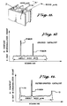
- Fig. 14 shows an example of the results obtained through tests performed by the inventors.
- the test specimen catalyst was a deteriorated catalyst which had been used in the treatment of coal exhaust gas. From this deteriorated catalyst, which was formed in the shape of a grid with a hole aperture of 6 mm, a catalyst thickness of 1.4 mm, a catalyst cross section of 150 mm, and a length of 500 mm, a piece was cut to a size convenient for the test, with a cross section of 15 mm square.
- a piece of commercially available sandpaper was attached to a square brass rod measuring 900 mm in length, 4 mm square in section.
- the denitration rate on the ground catalyst had recovered to a level approaching that of an unused catalyst, thus demonstrating the considerable effectiveness in catalyst regeneration achieved by grinding.
- the average thickness removed by the grinding process was 70 ⁇ m.
- the measurement of the denitration rate was performed at an AV (area velocity) of 25 Nm3/H.m2 and a mole ratio of 1.0.
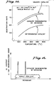
- a microanalyzer was used to analyze the cross section of the catalyst regenerated by grinding, and the Si distribution shown in Fig. 15 was obtained.
- blast treatment using sand, steel balls, etc. is also well known.
- wire brushes are used for lighter polishing and for removing foreign matter from surfaces. Because blast treatment uses small particles and air or some other fluid, it is well suited for large-volume processing and for improving processing efficiency. In addition, methods using wire brushes or some other type of brushes offer considerable possibilities for achieving a greater processing efficiency that for sandpaper.
- catalyst regeneration effectiveness it is preferred that all the surfaces of the catalyst which have come in contact with the exhaust gas be ground uniformly. Localized grinding has less catalyst regeneration effectiveness and, moreover, is not desirable for reasons concerning the strength of the catalyst.
- the following embodiments 1 to 3 are example of the methods investigated by the inventors selected with consideration for maintaining regeneration effectiveness through uniform grinding and for improving processing efficiency.
- a grid-shaped titanium-based catalyst (hole aperture of approximately 6 mm; inner wall thickness of approximately 1.4 mm) containing 0.7% by weight of V2O5 and 9% by weight of WO3, and measuring approximately 500 mm in length with a cross section of 150 mm square, which had been used in the denitration device of a coal-burning boiler, was used as a test specimen.
- Crushed silica sand having an average particle diameter of 125 ⁇ m was used as the abrasive material, and was caused to flow through the interior of the catalyst on a current of air flowing at a speed of 30 m per second with respect to the cross section of the catalyst, thus grinding the surfaces of the catalyst in order to perform catalyst regeneration.
- the catalyst edge protection grid 4a shown in Fig. 3 was used in order to prevent the wear of the edges of the catalyst.
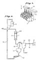
- Fig. 6 shows the process flow.
- the abrasive material was supplied at a rate of 4 kg per minute by a fixed-amount supply unit 5, the air output of the blower 6 was 40 m3 per minute, and the amount of time required for processing was 30 minutes.
- the catalyst 1 and the catalyst edge protection grid 4a were placed inside a sealed container 7, the blower 6 was connected to the bottom of this sealed container 7 via a cyclone 8 and a filter 10, and the silica sand was introduced from the top of the sealed container 7 on a current of air.
- the silica sand which has ground the surfaces of the catalyst flows into the cyclone together with the grinding dust and the air.
- the silica sand is separated together with the grinding dust and temporarily stored in the abrasive material hopper 11.
- a dust separator 12 separated the silica sand and the grinding dust, and the silica sand is circulated by a conveyor 13 back to the fixed-amount supply unit 5 in order to be used again.
- the air which contains fine particles of grinding dust, is sent from the cyclone 8 to the filter 10, where the fine particles of grinding dust are separated.
- 14 is a flow meter.
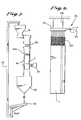
- the silica sand flowed through the catalyst holes by its own weight.
- a distributor 15 consisting of a large number of rods was provided at the top of the catalyst, and a vibrator 17 was mounted to the container 16 in which the catalyst 1 was placed in order to prevent the abrasive material from clogging the catalyst holes.
- the catalyst edge protection grid 4a shown in Fig. 3 was used in order to prevent the edges of the catalyst from becoming worn.
- the silica sand which has ground the surfaces of the catalyst falls into a hopper 18 together with the grinding dust, and the dust separator 12 separates the silica sand and the grinding dust.
- the silica sand is circulated by a conveyor 13 back to the fixed-amount supply unit 5 in order to be used again. After four hours of this silica sand flow treatment, the denitration rate and compression strength of the catalyst were measure. The results are shown in the following table.
- the polishing brushes 20 which were used were commercially available stainless steel brushes measuring 10 mm in diameter and 400 mm in length which had been cut to a cross section 7 mm square. The diameter of the brush wires was 0.08 mm. The cut brushes were mounted onto a brush mounting base 21, 20 in a row to correspond to the number of holes in one side of the test specimen catalyst.
- the brush mounting base 21 was moved up and down at a fixed stroke by a cam 22.
- 23 is a spring, and the spring 23 and the cam 22 form a reciprocating motion device 24.
- the brush mounting base 21 was moved up and down at a stroke of 140 mm with respect to the catalyst 1, which was held stationary, thus polishing the insides of the catalyst holes 2.
- the catalyst holes 2 were processed one row at a time, and the processing time for each row was one minute. Thus the amount of time required to process one catalyst was 20 minutes.
- the denitration rate and compression strength of the regenerated catalyst were measured, and the results are shown in the following table.
- Embodiments 1 and 2 are examples of methods suitable for catalyst regeneration using blast processing.
- this invention relates to the regeneration of a catalyst by grinding and removing the surface of the catalyst, during use in a denitration device used to treat (high-dust method) coal exhaust gas, the catalyst is constantly being subjected to grinding action by the fly ash, even though it is a very slight amount at a time.
- the grinding by the fly ash occurs at the edges of the catalyst and , with some small exceptions, is not observed at the sides of the catalyst. This is because the change in momentum resulting from the collision of each individual particle of fly ash with the catalyst is greatest at the edges and smallest at the sides.
- the momentum of the sand, steel balls, ceramic particles, or other abrasive material must be greater than that of the fly ash in order to ensure that the sides are ground.
- this can be achieved by such methods as using coarser particles for the abrasive material, increasing the density of the abrasive material, increasing the speed at which the abrasive material flows through the catalyst holes, etc., because, in any case, the change in the momentum of the abrasive material will be large at the edges of the catalyst than at the sides, a protective device is needed to prevent the frictional wear of the catalyst edges. In Embodiment 1 and 2, this is accomplished by the mounting of the protective grid on the catalyst edges with which the abrasive material collides.
- the abrasive material particle diameter and the flow speed will vary according to the abrasion resistance strength of the catalyst to be regenerated, generally selection can be made from within a range of 20 ⁇ 1000 ⁇ m for the average particle diameter and 15 ⁇ 60 m/sec for the air current flow speed.
- the average particle diameter for silica sand can be selected from within a range of 100 ⁇ 1500 ⁇ m.
- Methods for pressing the brush against the catalyst walls include (a) stretching the brush core to provide the core with tension and pressing in one direction; and (b) using a brush with a cross-sectional size that is larger than the diameter of the catalyst holes, thus using the flexure of the individual brush wires to uniformly apply frictional force to two or four surfaces simultaneously.
- Embodiment 3 uses this method.
- the cross-sectional size of the brush used will vary according to the configuration of the catalyst and the wire diameter and material of the brush, as shown in Embodiment 3, for a catalyst with holes measuring 6 mm square, using a brush with stainless steel (SUS304) wires measuring 0.08 mm in diameter, cutting the brush to an outer diameter of 7 mm square provides good results.
- SUS304 stainless steel
- the same type of catalyst edge protection grid as used in the blast processing method be mounted on both sides of the catalyst.
- a grid-shaped catalyst was used as an example and the methods for processing a single catalyst at a time where explained as illustrations, but the principles of the invention are not necessarily limited to these cases.
- this invention is especially effective in the regeneration of deteriorated catalysts which have been used to treat coal exhaust gas, it is also effective for catalysts which have been used for other kinds of gas treatment.
- the principles of this invention are the regeneration of a catalyst through a dry grinding method, regardless of the used hysteresis or history of the catalyst.
Landscapes
- Chemical & Material Sciences (AREA)
- Organic Chemistry (AREA)
- Chemical Kinetics & Catalysis (AREA)
- Engineering & Computer Science (AREA)
- Materials Engineering (AREA)
- Catalysts (AREA)
- Exhaust Gas Treatment By Means Of Catalyst (AREA)
Priority Applications (1)
| Application Number | Priority Date | Filing Date | Title |
|---|---|---|---|
| AT87303168T ATE69562T1 (de) | 1986-04-11 | 1987-04-10 | Verfahren zur trockenen regenerierung eines katalysators. |
Applications Claiming Priority (2)
| Application Number | Priority Date | Filing Date | Title |
|---|---|---|---|
| JP61083587A JPH0714486B2 (ja) | 1986-04-11 | 1986-04-11 | 触媒の乾式再生方法 |
| JP83587/86 | 1986-04-11 |
Publications (3)
| Publication Number | Publication Date |
|---|---|
| EP0241310A2 true EP0241310A2 (fr) | 1987-10-14 |
| EP0241310A3 EP0241310A3 (en) | 1988-03-16 |
| EP0241310B1 EP0241310B1 (fr) | 1991-11-21 |
Family
ID=13806623
Family Applications (1)
| Application Number | Title | Priority Date | Filing Date |
|---|---|---|---|
| EP87303168A Expired EP0241310B1 (fr) | 1986-04-11 | 1987-04-10 | Procédé de régénération à sec d'un catalyseur |
Country Status (5)
| Country | Link |
|---|---|
| EP (1) | EP0241310B1 (fr) |
| JP (1) | JPH0714486B2 (fr) |
| AT (1) | ATE69562T1 (fr) |
| CA (1) | CA1304065C (fr) |
| DE (1) | DE3774607D1 (fr) |
Cited By (7)
| Publication number | Priority date | Publication date | Assignee | Title |
|---|---|---|---|---|
| EP0568871A1 (fr) * | 1992-05-05 | 1993-11-10 | Siemens Aktiengesellschaft | Procédé et appareil pour le nettoyage d'un catalyseur en nid d'abeille |
| WO1995020434A1 (fr) * | 1994-01-27 | 1995-08-03 | Engelhard Corporation | Procede de recuperation de supports de catalyseurs |
| WO1995025591A1 (fr) * | 1994-03-21 | 1995-09-28 | Emitec Gesellschaft Für Emissionstechnologie Mbh | Procede de fabrication d'un convertisseur catalytique |
| US20110146722A1 (en) * | 2004-12-14 | 2011-06-23 | James Mark Underwood | Catalyst cleaning tool |
| CN104588129A (zh) * | 2014-12-31 | 2015-05-06 | 安科智慧城市技术(中国)有限公司 | 蜂窝式脱硝催化剂模块干法再生系统及方法 |
| EP2979761A4 (fr) * | 2013-03-28 | 2017-01-18 | The Chugoku Electric Power Co., Inc. | Procédé permettant la régénération d'un catalyseur de dénitrification |
| CN105856076B (zh) * | 2016-06-06 | 2019-03-12 | 江西应陶康顺实业有限公司 | 一种催化剂载体内孔壁表面打磨方法 |
Families Citing this family (16)
| Publication number | Priority date | Publication date | Assignee | Title |
|---|---|---|---|---|
| DE19628212B4 (de) * | 1996-07-12 | 2008-06-05 | Enbw Energy Solutions Gmbh | Verfahren zum Reinigen und/oder Regenerieren von ganz oder teilweise desaktivierten Katalysatoren zur Entstickung von Rauchgasen |
| KR20040042667A (ko) * | 2002-11-15 | 2004-05-20 | 유정근 | 폐탈질 촉매의 재생방법 |
| US7638039B2 (en) | 2004-06-15 | 2009-12-29 | Cormetech, Inc. | In-situ catalyst replacement |
| JP4994434B2 (ja) * | 2009-11-02 | 2012-08-08 | 中国電力株式会社 | 排ガス処理装置の性能回復方法 |
| JP5349359B2 (ja) * | 2010-02-09 | 2013-11-20 | 中国電力株式会社 | 脱硝触媒の再生方法 |
| JP5289364B2 (ja) * | 2010-03-17 | 2013-09-11 | 中国電力株式会社 | ハニカム触媒の研磨評価装置 |
| JP5555551B2 (ja) * | 2010-06-14 | 2014-07-23 | 株式会社日高ファインテクノロジーズ | 研削加工装置及び研削加工方法 |
| US8268743B2 (en) * | 2011-05-04 | 2012-09-18 | Steag Energy Services Gmbh | Pluggage removal method for SCR catalysts and systems |
| JP5701185B2 (ja) | 2011-09-09 | 2015-04-15 | 三菱重工業株式会社 | 脱硝触媒のso2酸化率上昇低減方法 |
| JP5634979B2 (ja) * | 2011-12-26 | 2014-12-03 | 中国電力株式会社 | 脱硝触媒の閉塞除去工具 |
| CN104028315A (zh) * | 2014-06-03 | 2014-09-10 | 陈凯 | 一种硫中毒选择性催化还原脱硝催化剂的再生方法 |
| CN104028317A (zh) * | 2014-06-03 | 2014-09-10 | 陈凯 | 一种磷中毒选择性催化还原脱硝催化剂的再生方法 |
| KR20190082259A (ko) | 2016-12-15 | 2019-07-09 | 미츠비시 히타치 파워 시스템즈 가부시키가이샤 | 사용이 끝난 탈질 촉매의 재생 방법 |
| WO2018211549A1 (fr) * | 2017-05-15 | 2018-11-22 | 中国電力株式会社 | Dispositif de broyage pour catalyseurs de dénitrification |
| JP6978345B2 (ja) * | 2018-02-28 | 2021-12-08 | 中国電力株式会社 | 脱硝触媒研磨装置及び脱硝触媒研磨方法 |
| JPWO2021171629A1 (fr) * | 2020-02-28 | 2021-09-02 |
Citations (5)
| Publication number | Priority date | Publication date | Assignee | Title |
|---|---|---|---|---|
| FR2133859A1 (fr) * | 1971-04-21 | 1972-12-01 | Norton Co | |
| FR2325421A1 (fr) * | 1975-09-25 | 1977-04-22 | Japan Gasoline | Procede pour enlever une matiere pulverulente deposee sur les surfaces interieures d'un appareil de contact |
| EP0172396A2 (fr) * | 1984-08-22 | 1986-02-26 | Didier-Werke Ag | Catalyseur pour l'élimination d'oxydes d'azote de gaz brûlés |
| EP0203028A1 (fr) * | 1985-05-17 | 1986-11-26 | Mitsubishi Jukogyo Kabushiki Kaisha | Procédé de régénération d'un catalyseur de dénitration de gaz d'échappement d'un appareil de combustion du charbon |
| EP0212043A1 (fr) * | 1985-05-07 | 1987-03-04 | Didier-Werke Ag | Procédé d'élimination d'oxyde d'azote et de suie de gaz d'échappement de moteurs et de brûleurs à huile lourde |
Family Cites Families (1)
| Publication number | Priority date | Publication date | Assignee | Title |
|---|---|---|---|---|
| JPS58150439A (ja) * | 1982-03-04 | 1983-09-07 | Mitsubishi Heavy Ind Ltd | 触媒の賦活方法 |
-
1986
- 1986-04-11 JP JP61083587A patent/JPH0714486B2/ja not_active Expired - Fee Related
-
1987
- 1987-04-10 CA CA000534472A patent/CA1304065C/fr not_active Expired - Lifetime
- 1987-04-10 DE DE8787303168T patent/DE3774607D1/de not_active Expired - Lifetime
- 1987-04-10 EP EP87303168A patent/EP0241310B1/fr not_active Expired
- 1987-04-10 AT AT87303168T patent/ATE69562T1/de not_active IP Right Cessation
Patent Citations (5)
| Publication number | Priority date | Publication date | Assignee | Title |
|---|---|---|---|---|
| FR2133859A1 (fr) * | 1971-04-21 | 1972-12-01 | Norton Co | |
| FR2325421A1 (fr) * | 1975-09-25 | 1977-04-22 | Japan Gasoline | Procede pour enlever une matiere pulverulente deposee sur les surfaces interieures d'un appareil de contact |
| EP0172396A2 (fr) * | 1984-08-22 | 1986-02-26 | Didier-Werke Ag | Catalyseur pour l'élimination d'oxydes d'azote de gaz brûlés |
| EP0212043A1 (fr) * | 1985-05-07 | 1987-03-04 | Didier-Werke Ag | Procédé d'élimination d'oxyde d'azote et de suie de gaz d'échappement de moteurs et de brûleurs à huile lourde |
| EP0203028A1 (fr) * | 1985-05-17 | 1986-11-26 | Mitsubishi Jukogyo Kabushiki Kaisha | Procédé de régénération d'un catalyseur de dénitration de gaz d'échappement d'un appareil de combustion du charbon |
Cited By (10)
| Publication number | Priority date | Publication date | Assignee | Title |
|---|---|---|---|---|
| EP0568871A1 (fr) * | 1992-05-05 | 1993-11-10 | Siemens Aktiengesellschaft | Procédé et appareil pour le nettoyage d'un catalyseur en nid d'abeille |
| WO1995020434A1 (fr) * | 1994-01-27 | 1995-08-03 | Engelhard Corporation | Procede de recuperation de supports de catalyseurs |
| US5820693A (en) * | 1994-01-27 | 1998-10-13 | Patchett; Joseph A. | Process for recovering catalysts supports |
| WO1995025591A1 (fr) * | 1994-03-21 | 1995-09-28 | Emitec Gesellschaft Für Emissionstechnologie Mbh | Procede de fabrication d'un convertisseur catalytique |
| US5877107A (en) * | 1994-03-21 | 1999-03-02 | Emitec Gesellschaft Fuer Emissions-Technologie Mbh | Method for producing a catalytic converter |
| US20110146722A1 (en) * | 2004-12-14 | 2011-06-23 | James Mark Underwood | Catalyst cleaning tool |
| EP2979761A4 (fr) * | 2013-03-28 | 2017-01-18 | The Chugoku Electric Power Co., Inc. | Procédé permettant la régénération d'un catalyseur de dénitrification |
| US10335780B2 (en) | 2013-03-28 | 2019-07-02 | The Chugoku Electric Power Co., Inc. | Method for regenerating denitrification catalyst |
| CN104588129A (zh) * | 2014-12-31 | 2015-05-06 | 安科智慧城市技术(中国)有限公司 | 蜂窝式脱硝催化剂模块干法再生系统及方法 |
| CN105856076B (zh) * | 2016-06-06 | 2019-03-12 | 江西应陶康顺实业有限公司 | 一种催化剂载体内孔壁表面打磨方法 |
Also Published As
| Publication number | Publication date |
|---|---|
| CA1304065C (fr) | 1992-06-23 |
| EP0241310A3 (en) | 1988-03-16 |
| DE3774607D1 (de) | 1992-01-02 |
| JPS62241555A (ja) | 1987-10-22 |
| ATE69562T1 (de) | 1991-12-15 |
| EP0241310B1 (fr) | 1991-11-21 |
| JPH0714486B2 (ja) | 1995-02-22 |
Similar Documents
| Publication | Publication Date | Title |
|---|---|---|
| EP0241310A2 (fr) | Procédé de régénération à sec d'un catalyseur | |
| CN103813857B (zh) | 用于scr催化剂和系统的堵塞去除方法 | |
| US7431904B2 (en) | Catalyst support material, catalysts prepared therefrom and process for the treatment of a flue gas | |
| EP0247965B1 (fr) | Dispositif pour le traitement d'un gaz de fumée | |
| US20180369800A1 (en) | A catalyst bed and method for reducing nitrogen oxides | |
| JP6775037B2 (ja) | 排ガス浄化用触媒 | |
| CA1133836A (fr) | Methode et appareil de filtration | |
| EP0203028A1 (fr) | Procédé de régénération d'un catalyseur de dénitration de gaz d'échappement d'un appareil de combustion du charbon | |
| US4360364A (en) | Filtering method and apparatus therefor | |
| JPS58146447A (ja) | 触媒の再生方法 | |
| Nam et al. | A pilot plant study for selective catalytic reduction of NO by NH3 over mordenite-type zeolite catalysts | |
| JP6245405B2 (ja) | 脱硝触媒の劣化評価方法 | |
| JP5349359B2 (ja) | 脱硝触媒の再生方法 | |
| JPS6315024B2 (fr) | ||
| Gimenes et al. | A model for particle collection in a turbulent bed contactor—New packings | |
| WO2018109904A1 (fr) | Procédé de régénération d'un catalyseur de dénitration usagé | |
| Doolin et al. | Laboratory Testing Procedure for Evaluation of Moving Bed Catalyst Attribution | |
| WO2021245841A1 (fr) | Dispositif d'abrasion de catalyseur de dénitration | |
| KR102270176B1 (ko) | 초고속 정전 초미세입자 제거장치가 장착된 탈황장치 | |
| Ramachandran | Particulate Controls: Dry Collectors | |
| WO2021245842A1 (fr) | Dispositif d'abrasion de catalyseur de dénitration | |
| EP3829739A1 (fr) | Tamis filtrant | |
| JP3901762B2 (ja) | 移動層反応槽の上部構造 | |
| JPS607793Y2 (ja) | 固気接触装置 | |
| Fujita et al. | Fabric-filter-supported catalyst for removal of harmful solid and gaseous compounds in municipal waste incinerator exhaust gas: characteristics of NO x reduction |
Legal Events
| Date | Code | Title | Description |
|---|---|---|---|
| PUAI | Public reference made under article 153(3) epc to a published international application that has entered the european phase |
Free format text: ORIGINAL CODE: 0009012 |
|
| 17P | Request for examination filed |
Effective date: 19870415 |
|
| AK | Designated contracting states |
Kind code of ref document: A2 Designated state(s): AT BE CH DE FR GB IT LI NL |
|
| PUAL | Search report despatched |
Free format text: ORIGINAL CODE: 0009013 |
|
| AK | Designated contracting states |
Kind code of ref document: A3 Designated state(s): AT BE CH DE FR GB IT LI NL |
|
| 17Q | First examination report despatched |
Effective date: 19890421 |
|
| GRAA | (expected) grant |
Free format text: ORIGINAL CODE: 0009210 |
|
| AK | Designated contracting states |
Kind code of ref document: B1 Designated state(s): AT BE CH DE FR GB IT LI NL |
|
| PG25 | Lapsed in a contracting state [announced via postgrant information from national office to epo] |
Ref country code: NL Effective date: 19911121 Ref country code: BE Effective date: 19911121 |
|
| REF | Corresponds to: |
Ref document number: 69562 Country of ref document: AT Date of ref document: 19911215 Kind code of ref document: T |
|
| REF | Corresponds to: |
Ref document number: 3774607 Country of ref document: DE Date of ref document: 19920102 |
|
| ITF | It: translation for a ep patent filed |
Owner name: MODIANO & ASSOCIATI S.R.L. |
|
| EN | Fr: translation not filed | ||
| PG25 | Lapsed in a contracting state [announced via postgrant information from national office to epo] |
Ref country code: FR Effective date: 19920410 |
|
| NLV1 | Nl: lapsed or annulled due to failure to fulfill the requirements of art. 29p and 29m of the patents act | ||
| PLBE | No opposition filed within time limit |
Free format text: ORIGINAL CODE: 0009261 |
|
| STAA | Information on the status of an ep patent application or granted ep patent |
Free format text: STATUS: NO OPPOSITION FILED WITHIN TIME LIMIT |
|
| 26N | No opposition filed | ||
| REG | Reference to a national code |
Ref country code: FR Ref legal event code: ST |
|
| REG | Reference to a national code |
Ref country code: GB Ref legal event code: IF02 |
|
| PGFP | Annual fee paid to national office [announced via postgrant information from national office to epo] |
Ref country code: GB Payment date: 20050406 Year of fee payment: 19 |
|
| PGFP | Annual fee paid to national office [announced via postgrant information from national office to epo] |
Ref country code: DE Payment date: 20050407 Year of fee payment: 19 |
|
| PGFP | Annual fee paid to national office [announced via postgrant information from national office to epo] |
Ref country code: AT Payment date: 20050413 Year of fee payment: 19 |
|
| PGFP | Annual fee paid to national office [announced via postgrant information from national office to epo] |
Ref country code: CH Payment date: 20050415 Year of fee payment: 19 |
|
| PG25 | Lapsed in a contracting state [announced via postgrant information from national office to epo] |
Ref country code: GB Free format text: LAPSE BECAUSE OF NON-PAYMENT OF DUE FEES Effective date: 20060410 Ref country code: AT Free format text: LAPSE BECAUSE OF NON-PAYMENT OF DUE FEES Effective date: 20060410 |
|
| PG25 | Lapsed in a contracting state [announced via postgrant information from national office to epo] |
Ref country code: LI Free format text: LAPSE BECAUSE OF NON-PAYMENT OF DUE FEES Effective date: 20060430 Ref country code: CH Free format text: LAPSE BECAUSE OF NON-PAYMENT OF DUE FEES Effective date: 20060430 |
|
| PGFP | Annual fee paid to national office [announced via postgrant information from national office to epo] |
Ref country code: IT Payment date: 20060430 Year of fee payment: 20 |
|
| PG25 | Lapsed in a contracting state [announced via postgrant information from national office to epo] |
Ref country code: DE Free format text: LAPSE BECAUSE OF NON-PAYMENT OF DUE FEES Effective date: 20061101 |
|
| REG | Reference to a national code |
Ref country code: CH Ref legal event code: PL |
|
| GBPC | Gb: european patent ceased through non-payment of renewal fee |
Effective date: 20060410 |