EP0241310A2 - Method for the dry regeneration of a catalyst - Google Patents
Method for the dry regeneration of a catalyst Download PDFInfo
- Publication number
- EP0241310A2 EP0241310A2 EP87303168A EP87303168A EP0241310A2 EP 0241310 A2 EP0241310 A2 EP 0241310A2 EP 87303168 A EP87303168 A EP 87303168A EP 87303168 A EP87303168 A EP 87303168A EP 0241310 A2 EP0241310 A2 EP 0241310A2
- Authority
- EP
- European Patent Office
- Prior art keywords
- catalyst
- abrasive material
- regeneration
- holes
- deteriorated
- Prior art date
- Legal status (The legal status is an assumption and is not a legal conclusion. Google has not performed a legal analysis and makes no representation as to the accuracy of the status listed.)
- Granted
Links
- 239000003054 catalyst Substances 0.000 title claims abstract description 252
- 238000000034 method Methods 0.000 title claims abstract description 66
- 238000011069 regeneration method Methods 0.000 title claims abstract description 47
- 230000008929 regeneration Effects 0.000 title claims abstract description 45
- VYPSYNLAJGMNEJ-UHFFFAOYSA-N Silicium dioxide Chemical compound O=[Si]=O VYPSYNLAJGMNEJ-UHFFFAOYSA-N 0.000 claims abstract description 56
- 239000003082 abrasive agent Substances 0.000 claims abstract description 47
- 239000004576 sand Substances 0.000 claims abstract description 20
- 239000000377 silicon dioxide Substances 0.000 claims abstract description 18
- 239000007789 gas Substances 0.000 description 33
- 238000000227 grinding Methods 0.000 description 32
- 238000012545 processing Methods 0.000 description 23
- 230000006866 deterioration Effects 0.000 description 21
- 239000002245 particle Substances 0.000 description 18
- 239000003245 coal Substances 0.000 description 15
- 238000012360 testing method Methods 0.000 description 14
- 239000000428 dust Substances 0.000 description 13
- 239000002344 surface layer Substances 0.000 description 10
- 239000004071 soot Substances 0.000 description 9
- 238000005406 washing Methods 0.000 description 8
- 238000009826 distribution Methods 0.000 description 7
- 238000005498 polishing Methods 0.000 description 7
- 230000008569 process Effects 0.000 description 7
- QGZKDVFQNNGYKY-UHFFFAOYSA-N Ammonia Chemical compound N QGZKDVFQNNGYKY-UHFFFAOYSA-N 0.000 description 6
- 239000010881 fly ash Substances 0.000 description 6
- 239000000446 fuel Substances 0.000 description 6
- 229910000831 Steel Inorganic materials 0.000 description 5
- 239000003921 oil Substances 0.000 description 5
- 239000011148 porous material Substances 0.000 description 5
- 239000010959 steel Substances 0.000 description 5
- PNEYBMLMFCGWSK-UHFFFAOYSA-N aluminium oxide Inorganic materials [O-2].[O-2].[O-2].[Al+3].[Al+3] PNEYBMLMFCGWSK-UHFFFAOYSA-N 0.000 description 4
- BIGPRXCJEDHCLP-UHFFFAOYSA-N ammonium bisulfate Chemical compound [NH4+].OS([O-])(=O)=O BIGPRXCJEDHCLP-UHFFFAOYSA-N 0.000 description 4
- 230000003197 catalytic effect Effects 0.000 description 4
- 238000010438 heat treatment Methods 0.000 description 4
- 239000000463 material Substances 0.000 description 4
- 230000008859 change Effects 0.000 description 3
- 238000006243 chemical reaction Methods 0.000 description 3
- 230000006835 compression Effects 0.000 description 3
- 238000007906 compression Methods 0.000 description 3
- 238000010586 diagram Methods 0.000 description 3
- 239000008188 pellet Substances 0.000 description 3
- 231100000614 poison Toxicity 0.000 description 3
- 238000009987 spinning Methods 0.000 description 3
- GWEVSGVZZGPLCZ-UHFFFAOYSA-N Titan oxide Chemical compound O=[Ti]=O GWEVSGVZZGPLCZ-UHFFFAOYSA-N 0.000 description 2
- 238000005299 abrasion Methods 0.000 description 2
- 239000007864 aqueous solution Substances 0.000 description 2
- 239000000919 ceramic Substances 0.000 description 2
- 229910052593 corundum Inorganic materials 0.000 description 2
- 230000008021 deposition Effects 0.000 description 2
- 239000010419 fine particle Substances 0.000 description 2
- 238000003505 heat denaturation Methods 0.000 description 2
- JEIPFZHSYJVQDO-UHFFFAOYSA-N iron(III) oxide Inorganic materials O=[Fe]O[Fe]=O JEIPFZHSYJVQDO-UHFFFAOYSA-N 0.000 description 2
- 230000001788 irregular Effects 0.000 description 2
- 229910052751 metal Inorganic materials 0.000 description 2
- 239000002184 metal Substances 0.000 description 2
- 239000002574 poison Substances 0.000 description 2
- 238000003825 pressing Methods 0.000 description 2
- 238000003672 processing method Methods 0.000 description 2
- 230000001681 protective effect Effects 0.000 description 2
- 230000009467 reduction Effects 0.000 description 2
- 238000011160 research Methods 0.000 description 2
- 239000007787 solid Substances 0.000 description 2
- 229910001220 stainless steel Inorganic materials 0.000 description 2
- 239000010935 stainless steel Substances 0.000 description 2
- 239000000126 substance Substances 0.000 description 2
- 229910001845 yogo sapphire Inorganic materials 0.000 description 2
- 229910001369 Brass Inorganic materials 0.000 description 1
- NINIDFKCEFEMDL-UHFFFAOYSA-N Sulfur Chemical compound [S] NINIDFKCEFEMDL-UHFFFAOYSA-N 0.000 description 1
- RTAQQCXQSZGOHL-UHFFFAOYSA-N Titanium Chemical compound [Ti] RTAQQCXQSZGOHL-UHFFFAOYSA-N 0.000 description 1
- 230000009471 action Effects 0.000 description 1
- 239000012670 alkaline solution Substances 0.000 description 1
- 229910021529 ammonia Inorganic materials 0.000 description 1
- 238000004458 analytical method Methods 0.000 description 1
- 230000015572 biosynthetic process Effects 0.000 description 1
- 239000010951 brass Substances 0.000 description 1
- 239000003153 chemical reaction reagent Substances 0.000 description 1
- 238000005520 cutting process Methods 0.000 description 1
- 238000000354 decomposition reaction Methods 0.000 description 1
- 230000003247 decreasing effect Effects 0.000 description 1
- 238000001514 detection method Methods 0.000 description 1
- -1 dimethyl siloxane Chemical class 0.000 description 1
- 238000009837 dry grinding Methods 0.000 description 1
- 230000000694 effects Effects 0.000 description 1
- 238000010828 elution Methods 0.000 description 1
- 230000001747 exhibiting effect Effects 0.000 description 1
- 238000002474 experimental method Methods 0.000 description 1
- 239000012530 fluid Substances 0.000 description 1
- 239000000295 fuel oil Substances 0.000 description 1
- 230000005484 gravity Effects 0.000 description 1
- 239000012784 inorganic fiber Substances 0.000 description 1
- 238000011835 investigation Methods 0.000 description 1
- 230000000873 masking effect Effects 0.000 description 1
- 238000005259 measurement Methods 0.000 description 1
- 229910000069 nitrogen hydride Inorganic materials 0.000 description 1
- 230000007096 poisonous effect Effects 0.000 description 1
- 229920001296 polysiloxane Polymers 0.000 description 1
- 230000036632 reaction speed Effects 0.000 description 1
- 230000007420 reactivation Effects 0.000 description 1
- 238000004904 shortening Methods 0.000 description 1
- 238000007086 side reaction Methods 0.000 description 1
- WBHQBSYUUJJSRZ-UHFFFAOYSA-M sodium bisulfate Chemical compound [Na+].OS([O-])(=O)=O WBHQBSYUUJJSRZ-UHFFFAOYSA-M 0.000 description 1
- 239000000243 solution Substances 0.000 description 1
- 229910052717 sulfur Inorganic materials 0.000 description 1
- 239000011593 sulfur Substances 0.000 description 1
- 150000003467 sulfuric acid derivatives Chemical class 0.000 description 1
- 239000010936 titanium Substances 0.000 description 1
- 229910052719 titanium Inorganic materials 0.000 description 1
Images


Classifications
-
- B01J35/56—
-
- B—PERFORMING OPERATIONS; TRANSPORTING
- B01—PHYSICAL OR CHEMICAL PROCESSES OR APPARATUS IN GENERAL
- B01J—CHEMICAL OR PHYSICAL PROCESSES, e.g. CATALYSIS OR COLLOID CHEMISTRY; THEIR RELEVANT APPARATUS
- B01J38/00—Regeneration or reactivation of catalysts, in general
-
- B—PERFORMING OPERATIONS; TRANSPORTING
- B01—PHYSICAL OR CHEMICAL PROCESSES OR APPARATUS IN GENERAL
- B01J—CHEMICAL OR PHYSICAL PROCESSES, e.g. CATALYSIS OR COLLOID CHEMISTRY; THEIR RELEVANT APPARATUS
- B01J8/00—Chemical or physical processes in general, conducted in the presence of fluids and solid particles; Apparatus for such processes
- B01J8/08—Chemical or physical processes in general, conducted in the presence of fluids and solid particles; Apparatus for such processes with moving particles
- B01J8/12—Chemical or physical processes in general, conducted in the presence of fluids and solid particles; Apparatus for such processes with moving particles moved by gravity in a downward flow
Definitions
- This invention relates to a highly efficient method for the dry regeneration of a catalyst whose performance has decreased (hereafter deteriorated catalyst) through use in a dry denitration device or other gas processing device, wherein the deteriorated catalyst is regenerated by using an abrasive material to grind the surfaces of the catalyst and thus grind off any foreign matter adhered to the catalyst surfaces, together with a part of the catalyst.
- dry denitration ammonia catalytic selective reduction (hereafter referred to as dry denitration) using a catalyst. Dry denitration first began to be used in commercial facilities around 1973, and its range of applicability has steadily increased, centering mainly on boilers using such fuel as gas and heavy oil, and in 1980 it also began to be used for treatment of the exhaust gas from coal-burning boilers.
- components of the catalyst such as Al2O3 or Fe2O3 are converted into sulfates by the SO X in the exhaust gas, thus making a loss of the catalytic function
- Fig. 10 shows one example of the configuration of a catalyst used for the denitration treatment of coal or oil exhaust gas.
- 1 indicates the catalyst, and 2 indicates the catalyst holes.
- 2 indicates the catalyst holes.
- the effective depth (the depth to which the catalyst contributes to the denitration reaction) of the catalyst is estimated to be approximately 100 ⁇ m, whether it is the result of chemical poison or clogging, any increase in the amount of Si or Ca, even if it is limited to within a depth of 100 ⁇ m, can be judged sufficient to explain the deterioration of the catalyst.
- the increase of Si and Ca in the surface layers of the catalyst are the greatest cause of deterioration in denitration catalysts used in the treatment of coal exhaust gas.
- the inventors attempted the regeneration of deteriorated catalysts which had been used to treat coal exhaust gas by using the heating methods and washing methods of prior art described earlier, but none of these methods provided sufficient results.
- the heating method especially, was completely ineffective, with no changes in the cross-sectional distribution of Si and Ca following heat treatment (catalyst exposed for three hours to hot air current of 430°C).
- the objective of this invention is to provide a method whereby catalysts can, with no practical reduction of the strength of the catalysts, be efficiently regenerated by grinding and removing the surface of the catalysts.
- the method for the dry regeneration of a catalyst in the first invention included in this application is characterized in that, for the regeneration of a deteriorated catalyst formed in the shape of a large number of tubes, a honeycomb, or a large number of plates, an abrasive material is used to grind the surfaces of the interiors of the many holes in the deteriorated catalyst.
- the method for the dry regeneration of a catalyst in the second invention included in this application is characterized in that, for the regeneration of a deteriorated catalyst formed in the shape of a large number of tubes, a honeycomb, or a large number of plates, a catalyst edge protection grid is first placed on top of the deteriorated catalyst, and then an abrasive material is caused to flow through the interiors of the catalyst holes in order to grind the interior surfaces of the catalyst holes.
- abrasive material used in these invention, and some possibilities include silica sand, steel balls, ceramic particles, brushes, sandpaper, files, etc. As long as the material has a harness exceeding that of the material of the catalyst, anything can be used. There are also no limitations on the shape of the abrasive material.
- the abrasive material 3 can be caused to flow through the interiors of the catalyst holes 2 on a current of air, or the abrasive material 3 can be caused to flow through the interiors of the catalyst holes by its own weight. Also, if the abrasive material is caused to flow by its own weight, it is preferred that vibration be added in order to prevent clogging, etc.
- a catalyst edge protection grid is placed on top of the catalyst 1.
- the catalyst edge protection grid 4a shown in Fig. 1 is the catalyst edge protection grid shown in Fig. 3 which has been fitted into place on the catalyst.
- the catalyst edge protection grid 4b and 4c shown in Fig. 2 is the catalyst edge protection grid shown in Fig. 4 or Fig. 5 which has been fitted into place on the catalyst.
- the catalyst can be formed in the shape of a large number of tubes, a honeycomb, or a large number of plates arranged in parallel.
- the catalyst edge protection grid is fabricated to match the shape of the catalyst so that it can be fitted onto the catalyst.
- Fig. 14 shows an example of the results obtained through tests performed by the inventors.
- the test specimen catalyst was a deteriorated catalyst which had been used in the treatment of coal exhaust gas. From this deteriorated catalyst, which was formed in the shape of a grid with a hole aperture of 6 mm, a catalyst thickness of 1.4 mm, a catalyst cross section of 150 mm, and a length of 500 mm, a piece was cut to a size convenient for the test, with a cross section of 15 mm square.
- a piece of commercially available sandpaper was attached to a square brass rod measuring 900 mm in length, 4 mm square in section.
- the denitration rate on the ground catalyst had recovered to a level approaching that of an unused catalyst, thus demonstrating the considerable effectiveness in catalyst regeneration achieved by grinding.
- the average thickness removed by the grinding process was 70 ⁇ m.
- the measurement of the denitration rate was performed at an AV (area velocity) of 25 Nm3/H.m2 and a mole ratio of 1.0.
- a microanalyzer was used to analyze the cross section of the catalyst regenerated by grinding, and the Si distribution shown in Fig. 15 was obtained.
- blast treatment using sand, steel balls, etc. is also well known.
- wire brushes are used for lighter polishing and for removing foreign matter from surfaces. Because blast treatment uses small particles and air or some other fluid, it is well suited for large-volume processing and for improving processing efficiency. In addition, methods using wire brushes or some other type of brushes offer considerable possibilities for achieving a greater processing efficiency that for sandpaper.
- catalyst regeneration effectiveness it is preferred that all the surfaces of the catalyst which have come in contact with the exhaust gas be ground uniformly. Localized grinding has less catalyst regeneration effectiveness and, moreover, is not desirable for reasons concerning the strength of the catalyst.
- the following embodiments 1 to 3 are example of the methods investigated by the inventors selected with consideration for maintaining regeneration effectiveness through uniform grinding and for improving processing efficiency.
- a grid-shaped titanium-based catalyst (hole aperture of approximately 6 mm; inner wall thickness of approximately 1.4 mm) containing 0.7% by weight of V2O5 and 9% by weight of WO3, and measuring approximately 500 mm in length with a cross section of 150 mm square, which had been used in the denitration device of a coal-burning boiler, was used as a test specimen.
- Crushed silica sand having an average particle diameter of 125 ⁇ m was used as the abrasive material, and was caused to flow through the interior of the catalyst on a current of air flowing at a speed of 30 m per second with respect to the cross section of the catalyst, thus grinding the surfaces of the catalyst in order to perform catalyst regeneration.
- the catalyst edge protection grid 4a shown in Fig. 3 was used in order to prevent the wear of the edges of the catalyst.
- Fig. 6 shows the process flow.
- the abrasive material was supplied at a rate of 4 kg per minute by a fixed-amount supply unit 5, the air output of the blower 6 was 40 m3 per minute, and the amount of time required for processing was 30 minutes.
- the catalyst 1 and the catalyst edge protection grid 4a were placed inside a sealed container 7, the blower 6 was connected to the bottom of this sealed container 7 via a cyclone 8 and a filter 10, and the silica sand was introduced from the top of the sealed container 7 on a current of air.
- the silica sand which has ground the surfaces of the catalyst flows into the cyclone together with the grinding dust and the air.
- the silica sand is separated together with the grinding dust and temporarily stored in the abrasive material hopper 11.
- a dust separator 12 separated the silica sand and the grinding dust, and the silica sand is circulated by a conveyor 13 back to the fixed-amount supply unit 5 in order to be used again.
- the air which contains fine particles of grinding dust, is sent from the cyclone 8 to the filter 10, where the fine particles of grinding dust are separated.
- 14 is a flow meter.
- the silica sand flowed through the catalyst holes by its own weight.
- a distributor 15 consisting of a large number of rods was provided at the top of the catalyst, and a vibrator 17 was mounted to the container 16 in which the catalyst 1 was placed in order to prevent the abrasive material from clogging the catalyst holes.
- the catalyst edge protection grid 4a shown in Fig. 3 was used in order to prevent the edges of the catalyst from becoming worn.
- the silica sand which has ground the surfaces of the catalyst falls into a hopper 18 together with the grinding dust, and the dust separator 12 separates the silica sand and the grinding dust.
- the silica sand is circulated by a conveyor 13 back to the fixed-amount supply unit 5 in order to be used again. After four hours of this silica sand flow treatment, the denitration rate and compression strength of the catalyst were measure. The results are shown in the following table.
- the polishing brushes 20 which were used were commercially available stainless steel brushes measuring 10 mm in diameter and 400 mm in length which had been cut to a cross section 7 mm square. The diameter of the brush wires was 0.08 mm. The cut brushes were mounted onto a brush mounting base 21, 20 in a row to correspond to the number of holes in one side of the test specimen catalyst.
- the brush mounting base 21 was moved up and down at a fixed stroke by a cam 22.
- 23 is a spring, and the spring 23 and the cam 22 form a reciprocating motion device 24.
- the brush mounting base 21 was moved up and down at a stroke of 140 mm with respect to the catalyst 1, which was held stationary, thus polishing the insides of the catalyst holes 2.
- the catalyst holes 2 were processed one row at a time, and the processing time for each row was one minute. Thus the amount of time required to process one catalyst was 20 minutes.
- the denitration rate and compression strength of the regenerated catalyst were measured, and the results are shown in the following table.
- Embodiments 1 and 2 are examples of methods suitable for catalyst regeneration using blast processing.
- this invention relates to the regeneration of a catalyst by grinding and removing the surface of the catalyst, during use in a denitration device used to treat (high-dust method) coal exhaust gas, the catalyst is constantly being subjected to grinding action by the fly ash, even though it is a very slight amount at a time.
- the grinding by the fly ash occurs at the edges of the catalyst and , with some small exceptions, is not observed at the sides of the catalyst. This is because the change in momentum resulting from the collision of each individual particle of fly ash with the catalyst is greatest at the edges and smallest at the sides.
- the momentum of the sand, steel balls, ceramic particles, or other abrasive material must be greater than that of the fly ash in order to ensure that the sides are ground.
- this can be achieved by such methods as using coarser particles for the abrasive material, increasing the density of the abrasive material, increasing the speed at which the abrasive material flows through the catalyst holes, etc., because, in any case, the change in the momentum of the abrasive material will be large at the edges of the catalyst than at the sides, a protective device is needed to prevent the frictional wear of the catalyst edges. In Embodiment 1 and 2, this is accomplished by the mounting of the protective grid on the catalyst edges with which the abrasive material collides.
- the abrasive material particle diameter and the flow speed will vary according to the abrasion resistance strength of the catalyst to be regenerated, generally selection can be made from within a range of 20 ⁇ 1000 ⁇ m for the average particle diameter and 15 ⁇ 60 m/sec for the air current flow speed.
- the average particle diameter for silica sand can be selected from within a range of 100 ⁇ 1500 ⁇ m.
- Methods for pressing the brush against the catalyst walls include (a) stretching the brush core to provide the core with tension and pressing in one direction; and (b) using a brush with a cross-sectional size that is larger than the diameter of the catalyst holes, thus using the flexure of the individual brush wires to uniformly apply frictional force to two or four surfaces simultaneously.
- Embodiment 3 uses this method.
- the cross-sectional size of the brush used will vary according to the configuration of the catalyst and the wire diameter and material of the brush, as shown in Embodiment 3, for a catalyst with holes measuring 6 mm square, using a brush with stainless steel (SUS304) wires measuring 0.08 mm in diameter, cutting the brush to an outer diameter of 7 mm square provides good results.
- SUS304 stainless steel
- the same type of catalyst edge protection grid as used in the blast processing method be mounted on both sides of the catalyst.
- a grid-shaped catalyst was used as an example and the methods for processing a single catalyst at a time where explained as illustrations, but the principles of the invention are not necessarily limited to these cases.
- this invention is especially effective in the regeneration of deteriorated catalysts which have been used to treat coal exhaust gas, it is also effective for catalysts which have been used for other kinds of gas treatment.
- the principles of this invention are the regeneration of a catalyst through a dry grinding method, regardless of the used hysteresis or history of the catalyst.
Landscapes
- Chemical & Material Sciences (AREA)
- Organic Chemistry (AREA)
- Chemical Kinetics & Catalysis (AREA)
- Engineering & Computer Science (AREA)
- Materials Engineering (AREA)
- Catalysts (AREA)
- Exhaust Gas Treatment By Means Of Catalyst (AREA)
Abstract
Description
- This invention relates to a highly efficient method for the dry regeneration of a catalyst whose performance has decreased (hereafter deteriorated catalyst) through use in a dry denitration device or other gas processing device, wherein the deteriorated catalyst is regenerated by using an abrasive material to grind the surfaces of the catalyst and thus grind off any foreign matter adhered to the catalyst surfaces, together with a part of the catalyst.
- With very few exceptions, the method of exhaust gas denitration used at electric power plants and other stationary release sources is ammonia catalytic selective reduction (hereafter referred to as dry denitration) using a catalyst. Dry denitration first began to be used in commercial facilities around 1973, and its range of applicability has steadily increased, centering mainly on boilers using such fuel as gas and heavy oil, and in 1980 it also began to be used for treatment of the exhaust gas from coal-burning boilers.
- Unlike other types of industrial-use catalysts, because dry denitration catalysts are used for the treatment of exhaust gases having irregular properties and containing soot, it is often difficult to adjust the operating conditions and conditions under which the catalyst is used for the purpose of preventing the deterioration of the catalyst and maintaining its durability. Thus, since 1980, there has been considerable research done in order to identify which of the indefinite yet presumed conditions contribute to the deterioration of the catalyst and to develop measures whereby its durability could be improved.
- At that time, the presumed causes of catalyst deterioration included: (a) components of the catalyst such as Al₂O₃ or Fe₂O₃ are converted into sulfates by the SOX in the exhaust gas, thus making a loss of the catalytic function; (b) K, Na, Li, or other basic alkaline elements in the soot cause a loss of the catalytic function; (c) masking or blinding of the catalyst surfaces by particles of soot, tar, etc.; (d) ammonia compounds such as NH₄HSO₄ are formed inside the micro pores in the catalyst by the NH₃ introduced as a reagent of the dry denitration reaction and the SOX in the exhaust gas, thus causing a loss of the catalytic function; and (e) heat denaturation of the catalyst.
- When gas is burned as the fuel, because there is almost no soot or SOX in the exhaust gas, there are no factors for deterioration other than the heat denaturation of the catalyst. On the other hand, when oil is burned as the fuel, the exhaust gas may contain relatively large amounts of SO₃, so factors (b) and (d) above can be considered the leading causes of deterioration.
- In addition, of the causes of deterioration listed above, concerning factor (a), since around 1975, in place of the catalysts of the past which consisted mainly of Al₂O₃, Fe₂O₃, etc., catalysts using TiO₂ as a carrier came into practical use, thus greatly increasing the durability of the catalyst with respect to SOX, and subsequently making possible the application of dry denitration in the treatment of exhaust gas containing SOX. Although concern regarding factors (b) through (e) has not been completely eliminated, with catalyst durability tests showing a durability of at least one year for gas-burning and oil-burning boilers, practically has advanced considerably.
- As dry denitration has progressed for gas-burning and oil-burning boilers, research has also been conducted on methods for the regeneration of the deteriorated catalysts. For example, regeneration methods in which the deteriorated catalyst is washed in an alkaline aqueous solution can be seen in Japanese Patent Provisional Publications Shows 52-35786 and Showa 52-63891 and methods for the regeneration of a deteriorated catalyst by treating it with heat are presented in Japanese Patent Provisional Publications Shows 52-26393 and Showa 52-26394.
- In addition, as described in Japanese Patent Provisional Publication Shows 54-61087, a method has also been proposed for the rotation polishing of plate-shaped catalysts, in which the dust adhered to the surfaces of the catalysts is removed by securing a large number of plate-shaped catalysts inside a reactor which revolves around a horizontal axis, placing particle-shaped solids such as sand or alumina inside the reactor, and then spinning the reactor.
- Although the catalyst regeneration methods mentioned above which use washing are also effective in removing the particles of soot, etc., which have adhered to the surfaces of the catalyst, they are primarily judged to be effective in washing out poisonous substances such as K, Na, and NH₄HSO₄ which have permeated into the catalyst. Furthermore, heat treatment, using operation within a certain fixed temperature, is effective in dispersing NH₄HSO₄ and other ammonia compounds which have accumulated inside the catalyst.
- In addition, for plate-shaped catalysts consisting of parallel metal screens filled with catalyst pellets, the method described in Japanese Patent Provisional Publication Showa 54-61087 has the objective of flaking off dust which has adhered and accumulated between the pellets in the surface layers of the plate-shaped catalysts, and it is effective in both the contact of the gas with the catalyst pellets which make up the catalyst, and in the regeneration reactivation of the catalyst remnants.
- After years of operating dry denitration devices for equipment burning gas and all but the lowest quality of oil as fuel, it has become clear that the actual catalyst deterioration is less than was originally feared. Currently it is common for catalysts to not require replacement or replenishment for six years or more or operation. Because the exhaust gas from coal-burning equipment contains large amounts of soot, there were many technological problems to be solved, such as measures to prevent abrasion or clogging of the catalyst, and thus practical application did not come until 1980, some time later than for oil-burning facilities.
- In tests performed by the inventors, it was clear that the deterioration with the passage of time of denitration catalysts used in the treatment of coal exhaust gases was considerably greater than for when oil was used as a fuel. The results of analyses of the catalyst before and after use performed in order to clearly identify the causes of this deterioration showed that, in most cases, there were no substantial changes in the content of basic elements such as K and Na which have a high potential for deterioration, nor was the change in the sulfur content, which would indicate the formation of NH₄HSO₄ inside the micro pores of the catalyst, sufficiently to explain the deterioration.
- Although the amount of K, Na, and other alkaline basic elements contained in coal exhaust gas soot (fly ash) is larger than for when oil is burned as a fuel, because the amount of SO₃ is relatively small in comparison to the amount of soot, and because the K, Na, and other basic elements are fused together with such oxides as silica and alumina and enclosed in a glass-like insoluble state, it can be assumed that, with very little reaction, the function as a catalyst poison is slight. In the fly ash elution tests carried out by the inventors, there was little solution of K, Na, etc., in an aqueous solution, thus supporting this theory.
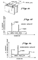
- Fig. 10 shows one example of the configuration of a catalyst used for the denitration treatment of coal or oil exhaust gas. 1 indicates the catalyst, and 2 indicates the catalyst holes. When an x-ray microanalyzer was used to analyze the cross section of a catalyst (for coal-burning facilities, the thicknesses most commonly used range from 0.8 to 1.8 mm) before and after using it for coal exhaust gas treatment, the cross-sectional distributions of Si shown in Fig. 12 and 13 were obtained. Concerning the catalyst used for this experiment, as shown in Fig. 11, the thickness of the catalyst 1 was 1400 µm (1.4 mm), and the
catalyst holes 2 measured 6000µm (6 mm) x 6000 µm (6 mm). - As shown in Fig. 12, for the unused catalyst, although peaks in the x-ray microanalyzer count appear at irregular positions inside the catalyst as a result of the detection of Si contained in the inorganic fiber used to maintain the strength of the catalyst, all other parts are flat. On the other hand, as shown in Fig. 13, for the deteriorated catalyst which has been used for the treatment of coal exhaust gas, an increase in the Si content appears (the projecting parts at both ends) for the surface layers of the catalyst, which have come in contact with the exhaust gas.
- When the same x-ray microanalyzer was used to investigate the distribution of Na, K, Ca, and other basic elements before and after the use of the catalyst, an increase in the Ca content was observed for the areas around the surface layers of the deteriorated catalyst, just as the Si. In investigations of the Si and Ca distributions in several varieties of catalyst samples with different origins, increases in the Si and Ca content of varying degrees were observed in the deteriorated catalysts in the areas near the surface layers.
- Although a close quantitative correlation between the degree of deterioration of the catalyst and the degree of increase of the Si or Ca content in the surface layers of the catalyst is as yet unconfirmed, a relationship was observed between the size of the microanalyzer count, which is an indicator of the content of Si, Ca, etc., and the degree of deterioration of the catalyst. For catalysts with severe deterioration, the cross-sectional distribution charts for Si and Ca generally featured large peaks in the areas of the surface layers.
- In almost all of the catalysts investigated thus far, the increase Si and Ca contents in the deteriorated catalysts were observed within a depth of 100 µm or less from the surface. At the present time, it is not yet clear whether the deterioration of the catalyst results from the increased amount Si or Ca combining with the components of the catalysts, or as a results of the clogging of the catalyst micro pores by particles containing Si or Ca.
- In this connection, when silicone having as its main component dimethyl siloxane, which has a high potential for decomposition under exposure to high temperatures and combining with the components of the catalyst, was placed into a container together with a catalyst for exposing at a temperature of approximately 400°C, the increase in Si was observed not only in the surface layers, but throughout the entire catalyst, thus exhibiting a marked difference from the increase in Si caused by coal exhaust gas. In this case, results different from those for a catalyst deteriorated by coal exhaust gas were obtained even for the properties of the side reactions in the catalyst. From this, it can be hypothesized that the increase of Si and Ca caused by coal exhaust gas results in the clogging of the micropores in the catalyst.
- However, because, as evaluated from the reaction speed and the size of the micro pores of the catalysts in practical use, the effective depth (the depth to which the catalyst contributes to the denitration reaction) of the catalyst is estimated to be approximately 100 µm, whether it is the result of chemical poison or clogging, any increase in the amount of Si or Ca, even if it is limited to within a depth of 100µm, can be judged sufficient to explain the deterioration of the catalyst. Furthermore, concerning the other causes of deterioration, as mentioned earlier, because not changes sufficient to explain the deterioration occur, it is believed that the increase of Si and Ca in the surface layers of the catalyst are the greatest cause of deterioration in denitration catalysts used in the treatment of coal exhaust gas. When considered from the view point of the regeneration of deteriorated catalysts, the fact that deterioration of the catalyst is caused, at least in the end result, by changes which occur in the area extending from the surface layers to a fixed depth is extremely meaningful.
- The inventors attempted the regeneration of deteriorated catalysts which had been used to treat coal exhaust gas by using the heating methods and washing methods of prior art described earlier, but none of these methods provided sufficient results. The heating method, especially, was completely ineffective, with no changes in the cross-sectional distribution of Si and Ca following heat treatment (catalyst exposed for three hours to hot air current of 430°C).
- In addition, when the washing method was used, although some effectiveness in removing the Si and Ca was observed, there were problems involving the washing out of some of the effective components of the catalyst and concerning the strength of the catalyst after it had been washed. In order to prevent this washing out of the effective components of the catalyst, an alkaline solution can be used, and there is also a method of restoring the effective components after washing, but in either case the treatment becomes complicated. Also, in order to remove a meaningful amount of Si and Ca, the catalyst must be washed for an extended length of time, even supposing that supplementary means such as ultrasonic waves are used. Thus, washing has a considerable effect on the strength of the catalyst, and practical application is judged to be difficult.
- In addition, in the method described in Japanese Patent Provisional Publication Shows 54-61087, particle-shaped solids are caused to collide with plate-shaped catalysts inside a spinning reactor so that the dust adhered to the surfaces of the catalysts is flaked off by the resulting friction, and there is no suggestion for the technological idea of grinding the surfaces of the catalysts. Furthermore, the practical application of the structure for spinning the reactor is extremely difficult, and, especially when the catalysts have been used to treat a gas which has considerable soot loading, such as coal exhaust gas does, there is the strong possibility that the reactor could become clogged.
- Focusing on the fact that the deterioration of a catalyst in the treatment of coal exhaust gas generally results from the deposition of particles of Si, Ca, etc., in the areas of the surface layers of the catalyst, and that this particle deposition is limited to a depth of approximately 100 µm, at most within 200 µm, from the catalyst surface, the inventors have proposed this invention in consideration of the various points mentioned above. The objective of this invention is to provide a method whereby catalysts can, with no practical reduction of the strength of the catalysts, be efficiently regenerated by grinding and removing the surface of the catalysts.
- Embodiments of the invention will now be described in more detail and by way of example, with reference to the accompanying drawings in which:-
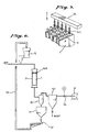
- Fig. 1 is an explanatory diagram showing one example of this invention's method for the dry regeneration of a catalyst.
- Fig. 2 is an explanatory diagram showing another example of the method of this invention.
- Figs. 3 through 5 are perspective views each of one example of the catalyst edge protection grid used in the method of this invention.
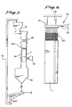
- Fig. 6 is a flowchart showing the catalyst regeneration processing using the air-current grinding method in Embodiment 1 of this invention.
- Fig. 7 is a flowchart showing the catalyst regeneration processing using the abrasive material gravity flow method of
Embodiment 2 of this invention. - Fig. 8 is an explanatory diagram showing the catalyst regeneration processing using the brush polishing method of
Embodiment 3 of this invention. - Fig. 9 is an expanded perspective view of the essential part of Fig. 6.
- Fig. 10 is a perspective view showing one example of the configuration of the catalysts for which the method of this invention can be used.
- Fig. 11 is an enlargement of a part of Fig. 10.
- Fig. 12 is a graph showing the Si content of an unused catalyst.
- Fig. 13 is a graph showing the Si content of a deteriorated catalyst.
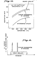
- Fig. 14 is a graph showing one example of the test results for catalyst regeneration using grinding.
- Fig. 15 is an Si distribution graph of the results when an x-ray microanalyzer was used to analyze the cross section of a catalyst regenerated by grinding.
- The method for the dry regeneration of a catalyst in the first invention included in this application is characterized in that, for the regeneration of a deteriorated catalyst formed in the shape of a large number of tubes, a honeycomb, or a large number of plates, an abrasive material is used to grind the surfaces of the interiors of the many holes in the deteriorated catalyst.
- In addition, the method for the dry regeneration of a catalyst in the second invention included in this application is characterized in that, for the regeneration of a deteriorated catalyst formed in the shape of a large number of tubes, a honeycomb, or a large number of plates, a catalyst edge protection grid is first placed on top of the deteriorated catalyst, and then an abrasive material is caused to flow through the interiors of the catalyst holes in order to grind the interior surfaces of the catalyst holes.
- There are no special limitations on the abrasive material used in these invention, and some possibilities include silica sand, steel balls, ceramic particles, brushes, sandpaper, files, etc. As long as the material has a harness exceeding that of the material of the catalyst, anything can be used. There are also no limitations on the shape of the abrasive material.
- If the abrasive material is particle-shaped, as shown in Figs. 1 and 2, the
abrasive material 3 can be caused to flow through the interiors of the catalyst holes 2 on a current of air, or theabrasive material 3 can be caused to flow through the interiors of the catalyst holes by its own weight. Also, if the abrasive material is caused to flow by its own weight, it is preferred that vibration be added in order to prevent clogging, etc. - In addition, in order to protect the top of the catalyst 1, a catalyst edge protection grid is placed on top of the catalyst 1. The catalyst
edge protection grid 4a shown in Fig. 1 is the catalyst edge protection grid shown in Fig. 3 which has been fitted into place on the catalyst. The catalyst edge protection grid 4b and 4c shown in Fig. 2 is the catalyst edge protection grid shown in Fig. 4 or Fig. 5 which has been fitted into place on the catalyst. - In addition to the grid shape shown in Fig. 10, the catalyst can be formed in the shape of a large number of tubes, a honeycomb, or a large number of plates arranged in parallel. The catalyst edge protection grid is fabricated to match the shape of the catalyst so that it can be fitted onto the catalyst.
- The following is an explanation of a test example and the embodiments of the invention.
- Fig. 14 shows an example of the results obtained through tests performed by the inventors. The test specimen catalyst was a deteriorated catalyst which had been used in the treatment of coal exhaust gas. From this deteriorated catalyst, which was formed in the shape of a grid with a hole aperture of 6 mm, a catalyst thickness of 1.4 mm, a catalyst cross section of 150 mm, and a length of 500 mm, a piece was cut to a size convenient for the test, with a cross section of 15 mm square. For the abrasive material, a piece of commercially available sandpaper was attached to a square brass rod measuring 900 mm in length, 4 mm square in section.
- As shown in Fig. 14, the denitration rate on the ground catalyst had recovered to a level approaching that of an unused catalyst, thus demonstrating the considerable effectiveness in catalyst regeneration achieved by grinding. Note that, as estimated by comparing the weight of the catalyst before and after grinding, the average thickness removed by the grinding process was 70 µm. Also, the measurement of the denitration rate was performed at an AV (area velocity) of 25 Nm³/H.m² and a mole ratio of 1.0.
- After the denitration rate was measured, a microanalyzer was used to analyze the cross section of the catalyst regenerated by grinding, and the Si distribution shown in Fig. 15 was obtained.
- Although there are no limitations on the grinding method used for the regeneration of a catalyst by grinding, the processing capacity of the grinding method described above, where sandpaper was attached to a metal rod, has a low processing efficiency and cannot necessarily be said to be well suited for practical application. In the practical application of the grinding method of catalyst regeneration, it is preferred that ways to improve processing efficiency be utilized.
- As means for grinding the surface of steel and other materials, in addition to sandpaper and files, blast treatment using sand, steel balls, etc., is also well known. Also, wire brushes are used for lighter polishing and for removing foreign matter from surfaces. Because blast treatment uses small particles and air or some other fluid, it is well suited for large-volume processing and for improving processing efficiency. In addition, methods using wire brushes or some other type of brushes offer considerable possibilities for achieving a greater processing efficiency that for sandpaper.
- However, from the viewpoint of catalyst regeneration effectiveness, it is preferred that all the surfaces of the catalyst which have come in contact with the exhaust gas be ground uniformly. Localized grinding has less catalyst regeneration effectiveness and, moreover, is not desirable for reasons concerning the strength of the catalyst.
- The following embodiments 1 to 3 are example of the methods investigated by the inventors selected with consideration for maintaining regeneration effectiveness through uniform grinding and for improving processing efficiency.
- A grid-shaped titanium-based catalyst (hole aperture of approximately 6 mm; inner wall thickness of approximately 1.4 mm) containing 0.7% by weight of V₂O₅ and 9% by weight of WO₃, and measuring approximately 500 mm in length with a cross section of 150 mm square, which had been used in the denitration device of a coal-burning boiler, was used as a test specimen. Crushed silica sand having an average particle diameter of 125 µm was used as the abrasive material, and was caused to flow through the interior of the catalyst on a current of air flowing at a speed of 30 m per second with respect to the cross section of the catalyst, thus grinding the surfaces of the catalyst in order to perform catalyst regeneration. At this time, the catalyst
edge protection grid 4a shown in Fig. 3 was used in order to prevent the wear of the edges of the catalyst. Fig. 6 shows the process flow. - The abrasive material was supplied at a rate of 4 kg per minute by a fixed-
amount supply unit 5, the air output of the blower 6 was 40 m³ per minute, and the amount of time required for processing was 30 minutes. - The catalyst 1 and the catalyst
edge protection grid 4a were placed inside a sealedcontainer 7, the blower 6 was connected to the bottom of this sealedcontainer 7 via a cyclone 8 and afilter 10, and the silica sand was introduced from the top of the sealedcontainer 7 on a current of air. - The silica sand which has ground the surfaces of the catalyst flows into the cyclone together with the grinding dust and the air. Here, the silica sand is separated together with the grinding dust and temporarily stored in the
abrasive material hopper 11. Next. adust separator 12 separated the silica sand and the grinding dust, and the silica sand is circulated by aconveyor 13 back to the fixed-amount supply unit 5 in order to be used again. - Meanwhile, the air, which contains fine particles of grinding dust, is sent from the cyclone 8 to the
filter 10, where the fine particles of grinding dust are separated. 14 is a flow meter. - As shown in the following table, the regeneration processing greatly restored the denitration rate, and although the grinding caused a slight loss of compression strength, it was clear that this presented no problems for practical application.
- The same catalyst test specimen as for Embodiment 1 was used, and catalyst regeneration was performed by causing the abrasive material to flow through the catalyst by its own weight. The processing flow has as shown in Fig. 7. Crushed silica sand having an average particle diameter of 840 µm was used as the abrasive material, and it was supplied at a rate of 6 kg per minute by the fixed-
amount supply unit 5. - The silica sand flowed through the catalyst holes by its own weight. In order to scatter the silica sand uniformly, a
distributor 15 consisting of a large number of rods was provided at the top of the catalyst, and avibrator 17 was mounted to thecontainer 16 in which the catalyst 1 was placed in order to prevent the abrasive material from clogging the catalyst holes. As for Embodiment 1, the catalystedge protection grid 4a shown in Fig. 3 was used in order to prevent the edges of the catalyst from becoming worn. - The silica sand which has ground the surfaces of the catalyst falls into a
hopper 18 together with the grinding dust, and thedust separator 12 separates the silica sand and the grinding dust. The silica sand is circulated by aconveyor 13 back to the fixed-amount supply unit 5 in order to be used again. After four hours of this silica sand flow treatment, the denitration rate and compression strength of the catalyst were measure. The results are shown in the following table. - The same catalyst test specimen as for Embodiment 1 was used, and catalyst regeneration was performed by using a brush polishing method. The processing procedures are shown in Figs. 8 and 9.
- The polishing brushes 20 which were used were commercially available stainless steel brushes measuring 10 mm in diameter and 400 mm in length which had been cut to a
cross section 7 mm square. The diameter of the brush wires was 0.08 mm. The cut brushes were mounted onto abrush mounting base - The
brush mounting base 21 was moved up and down at a fixed stroke by acam 22. 23 is a spring, and thespring 23 and thecam 22 form areciprocating motion device 24. Thebrush mounting base 21 was moved up and down at a stroke of 140 mm with respect to the catalyst 1, which was held stationary, thus polishing the insides of the catalyst holes 2. - The catalyst holes 2 were processed one row at a time, and the processing time for each row was one minute. Thus the amount of time required to process one catalyst was 20 minutes. The denitration rate and compression strength of the regenerated catalyst were measured, and the results are shown in the following table.

- As shown above,
Embodiments 1 and 2 are examples of methods suitable for catalyst regeneration using blast processing. - Although this invention relates to the regeneration of a catalyst by grinding and removing the surface of the catalyst, during use in a denitration device used to treat (high-dust method) coal exhaust gas, the catalyst is constantly being subjected to grinding action by the fly ash, even though it is a very slight amount at a time. As shown in Fig. 10, the grinding by the fly ash occurs at the edges of the catalyst and , with some small exceptions, is not observed at the sides of the catalyst. This is because the change in momentum resulting from the collision of each individual particle of fly ash with the catalyst is greatest at the edges and smallest at the sides.
- In order to make possible the regeneration of a catalyst by blast processing, the momentum of the sand, steel balls, ceramic particles, or other abrasive material must be greater than that of the fly ash in order to ensure that the sides are ground. Although this can be achieved by such methods as using coarser particles for the abrasive material, increasing the density of the abrasive material, increasing the speed at which the abrasive material flows through the catalyst holes, etc., because, in any case, the change in the momentum of the abrasive material will be large at the edges of the catalyst than at the sides, a protective device is needed to prevent the frictional wear of the catalyst edges. In
Embodiment 1 and 2, this is accomplished by the mounting of the protective grid on the catalyst edges with which the abrasive material collides. - With the method in Embodiment 1, where the abrasive material is scattered and carried through the catalyst holes by an air current, the smaller the particle size of the abrasive material, the more uniform the effectiveness of the grinding will be. However, when using small-diameter abrasive material, a higher flow speed is needed and more power will be required to drive the blower, so appropriate selection must be made accordingly. Although the abrasive material particle diameter and the flow speed will vary according to the abrasion resistance strength of the catalyst to be regenerated, generally selection can be made from within a range of 20 ∼ 1000 µm for the average particle diameter and 15 ∼ 60 m/sec for the air current flow speed.
- With the method of
Embodiment 2, where the abrasive material flows through the catalyst holes by its own weight, there are the advantages that the regeneration processing equipment is simpler, and that no power is required to drive a blower. However, there is the disadvantage that, even if the abrasive material particle diameter is increased, the time required for processing will be longer. In addition, for this gravity-flow method, it is preferred that means for scattering the abrasive material uniformly and means for preventing the abrasive material from clogging the catalyst holes also be included. With the gravity-flow method, although the particle diameter of the abrasive material will vary according to the characteristics of the catalyst, just as for the air-current grinding method, generally the average particle diameter for silica sand can be selected from within a range of 100 ∼ 1500 µm. - With the method of
Embodiment 3, where brush polishing is used, because commercially available brushes usually cannot be used as it is, they must be cut to the necessary dimensions. In order to provide each of the individual wires of the brush with frictional strength, it is preferred that the brush core be thin. In addition, because the brush core is thin and the length of the catalyst is usually 400 ∼ 1000 mm, is difficult to use the rigidity of the brush core to press the brush against the walls of the catalyst. Methods for pressing the brush against the catalyst walls include (a) stretching the brush core to provide the core with tension and pressing in one direction; and (b) using a brush with a cross-sectional size that is larger than the diameter of the catalyst holes, thus using the flexure of the individual brush wires to uniformly apply frictional force to two or four surfaces simultaneously. - In the inventors' tests, method (b) above provided goods results, and
Embodiment 3 uses this method. Although the cross-sectional size of the brush used will vary according to the configuration of the catalyst and the wire diameter and material of the brush, as shown inEmbodiment 3, for a catalyst with holes measuring 6 mm square, using a brush with stainless steel (SUS304) wires measuring 0.08 mm in diameter, cutting the brush to an outer diameter of 7 mm square provides good results. - In addition, although it is not used in the embodiment, depending on the characteristics of the brush used and the method of applying reciprocating motion, it may be preferred that the same type of catalyst edge protection grid as used in the blast processing method be mounted on both sides of the catalyst. In
Embodiment 3, the explanation dealt with the case where the brushes were inserted into the catalyst holes the full length or nearly the full length of the holes, but it is also possible to polish the surfaces of the catalyst by inserting the brushes only partway into the catalyst holes and lengthening the stroke. - In the embodiments, a grid-shaped catalyst was used as an example and the methods for processing a single catalyst at a time where explained as illustrations, but the principles of the invention are not necessarily limited to these cases. In addition to grid-shaped catalysts, it is also possible to regenerate plate-shaped catalysts using the principles of this invention, and, because multiple catalysts are often stored together in a steel container, it is also possible to either process these catalysts while they remain in the container or to process them without removing them from the reactor.
- In addition, using the blast processing method of
Embodiments 1 and 2, it is also possible to process the catalysts either individually or to arrange multiple catalysts in a container serially in multiple layers and process them simultaneously, thus shortening the time required for processing and reducing processing costs. Furthermore, although this invention is especially effective in the regeneration of deteriorated catalysts which have been used to treat coal exhaust gas, it is also effective for catalysts which have been used for other kinds of gas treatment. The principles of this invention are the regeneration of a catalyst through a dry grinding method, regardless of the used hysteresis or history of the catalyst. - As explained above, using the method of this invention, when a catalyst which has been performed in the shape of a large number of small tubes, a honeycomb, or a large number of plates becomes deteriorated, by grinding the surfaces of the deteriorated catalyst with an abrasive material it is possible to display an excellent regeneration effectiveness. There is also the additional effectiveness that, because the grinding is performed while the catalyst is in a stationary state, there is little power required, and the equipment is extremely simple.
Claims (9)
Priority Applications (1)
| Application Number | Priority Date | Filing Date | Title |
|---|---|---|---|
| AT87303168T ATE69562T1 (en) | 1986-04-11 | 1987-04-10 | PROCEDURE FOR DRY REGENERATION OF A CATALYST. |
Applications Claiming Priority (2)
| Application Number | Priority Date | Filing Date | Title |
|---|---|---|---|
| JP61083587A JPH0714486B2 (en) | 1986-04-11 | 1986-04-11 | Dry regeneration method of catalyst |
| JP83587/86 | 1986-04-11 |
Publications (3)
| Publication Number | Publication Date |
|---|---|
| EP0241310A2 true EP0241310A2 (en) | 1987-10-14 |
| EP0241310A3 EP0241310A3 (en) | 1988-03-16 |
| EP0241310B1 EP0241310B1 (en) | 1991-11-21 |
Family
ID=13806623
Family Applications (1)
| Application Number | Title | Priority Date | Filing Date |
|---|---|---|---|
| EP87303168A Expired EP0241310B1 (en) | 1986-04-11 | 1987-04-10 | Method for the dry regeneration of a catalyst |
Country Status (5)
| Country | Link |
|---|---|
| EP (1) | EP0241310B1 (en) |
| JP (1) | JPH0714486B2 (en) |
| AT (1) | ATE69562T1 (en) |
| CA (1) | CA1304065C (en) |
| DE (1) | DE3774607D1 (en) |
Cited By (7)
| Publication number | Priority date | Publication date | Assignee | Title |
|---|---|---|---|---|
| EP0568871A1 (en) * | 1992-05-05 | 1993-11-10 | Siemens Aktiengesellschaft | Apparatus and process to clean a honeycomb catalyst |
| WO1995020434A1 (en) * | 1994-01-27 | 1995-08-03 | Engelhard Corporation | Process for recovering catalyst supports |
| WO1995025591A1 (en) * | 1994-03-21 | 1995-09-28 | Emitec Gesellschaft Für Emissionstechnologie Mbh | Process for producing a catalytic converter |
| US20110146722A1 (en) * | 2004-12-14 | 2011-06-23 | James Mark Underwood | Catalyst cleaning tool |
| CN104588129A (en) * | 2014-12-31 | 2015-05-06 | 安科智慧城市技术(中国)有限公司 | Dry-process regeneration system and method of honeycomb type denitration catalyst module |
| EP2979761A4 (en) * | 2013-03-28 | 2017-01-18 | The Chugoku Electric Power Co., Inc. | Method for regenerating denitrification catalyst |
| CN105856076B (en) * | 2016-06-06 | 2019-03-12 | 江西应陶康顺实业有限公司 | A kind of catalyst carrier bore wall polishing process |
Families Citing this family (16)
| Publication number | Priority date | Publication date | Assignee | Title |
|---|---|---|---|---|
| DE19628212B4 (en) * | 1996-07-12 | 2008-06-05 | Enbw Energy Solutions Gmbh | Process for purifying and / or regenerating completely or partially deactivated catalysts for denitrification of flue gases |
| KR20040042667A (en) * | 2002-11-15 | 2004-05-20 | 유정근 | Method for recycling waste de-NOx catalyst |
| US7638039B2 (en) | 2004-06-15 | 2009-12-29 | Cormetech, Inc. | In-situ catalyst replacement |
| JP4994434B2 (en) * | 2009-11-02 | 2012-08-08 | 中国電力株式会社 | Performance recovery method for exhaust gas treatment equipment |
| JP5349359B2 (en) * | 2010-02-09 | 2013-11-20 | 中国電力株式会社 | Denitration catalyst regeneration method |
| JP5289364B2 (en) * | 2010-03-17 | 2013-09-11 | 中国電力株式会社 | Polishing evaluation device for honeycomb catalyst |
| JP5555551B2 (en) * | 2010-06-14 | 2014-07-23 | 株式会社日高ファインテクノロジーズ | Grinding apparatus and grinding method |
| US8268743B2 (en) * | 2011-05-04 | 2012-09-18 | Steag Energy Services Gmbh | Pluggage removal method for SCR catalysts and systems |
| JP5701185B2 (en) | 2011-09-09 | 2015-04-15 | 三菱重工業株式会社 | Method for reducing SO2 oxidation rate increase of denitration catalyst |
| JP5634979B2 (en) * | 2011-12-26 | 2014-12-03 | 中国電力株式会社 | Denitration catalyst blockage removal tool |
| CN104028317A (en) * | 2014-06-03 | 2014-09-10 | 陈凯 | Regeneration method of phosphorus-poisoned selective catalytic reduction (SCR) denitrification catalyst |
| CN104028315A (en) * | 2014-06-03 | 2014-09-10 | 陈凯 | Regeneration method of sulfur-poisoned selective catalytic reduction (SCR) denitrification catalyst |
| CN110072621A (en) * | 2016-12-15 | 2019-07-30 | 三菱日立电力系统株式会社 | The regeneration method of used denitrating catalyst |
| WO2018211549A1 (en) * | 2017-05-15 | 2018-11-22 | 中国電力株式会社 | Grinding device for denitrification catalysts |
| JP6978345B2 (en) * | 2018-02-28 | 2021-12-08 | 中国電力株式会社 | Denitration catalyst polishing device and denitration catalyst polishing method |
| JPWO2021171629A1 (en) * | 2020-02-28 | 2021-09-02 |
Citations (5)
| Publication number | Priority date | Publication date | Assignee | Title |
|---|---|---|---|---|
| FR2133859A1 (en) * | 1971-04-21 | 1972-12-01 | Norton Co | |
| FR2325421A1 (en) * | 1975-09-25 | 1977-04-22 | Japan Gasoline | METHOD FOR REMOVING PULVERULENT MATERIAL DEPOSITED ON THE INTERIOR SURFACES OF A CONTACT APPARATUS |
| EP0172396A2 (en) * | 1984-08-22 | 1986-02-26 | Didier-Werke Ag | Catalyst for separating oxides of nitrogen from combustion gases |
| EP0203028A1 (en) * | 1985-05-17 | 1986-11-26 | Mitsubishi Jukogyo Kabushiki Kaisha | Method for regenerating a denitration catalyst for exhaust gases from coal-burning apparatus |
| EP0212043A1 (en) * | 1985-05-07 | 1987-03-04 | Didier-Werke Ag | Process for removal of nitrogen oxide and soot from the exhaust gases of heavy oil engines and heavy oil burners |
Family Cites Families (1)
| Publication number | Priority date | Publication date | Assignee | Title |
|---|---|---|---|---|
| JPS58150439A (en) * | 1982-03-04 | 1983-09-07 | Mitsubishi Heavy Ind Ltd | Activation of catalyst |
-
1986
- 1986-04-11 JP JP61083587A patent/JPH0714486B2/en not_active Expired - Fee Related
-
1987
- 1987-04-10 EP EP87303168A patent/EP0241310B1/en not_active Expired
- 1987-04-10 CA CA000534472A patent/CA1304065C/en not_active Expired - Lifetime
- 1987-04-10 AT AT87303168T patent/ATE69562T1/en not_active IP Right Cessation
- 1987-04-10 DE DE8787303168T patent/DE3774607D1/en not_active Expired - Lifetime
Patent Citations (5)
| Publication number | Priority date | Publication date | Assignee | Title |
|---|---|---|---|---|
| FR2133859A1 (en) * | 1971-04-21 | 1972-12-01 | Norton Co | |
| FR2325421A1 (en) * | 1975-09-25 | 1977-04-22 | Japan Gasoline | METHOD FOR REMOVING PULVERULENT MATERIAL DEPOSITED ON THE INTERIOR SURFACES OF A CONTACT APPARATUS |
| EP0172396A2 (en) * | 1984-08-22 | 1986-02-26 | Didier-Werke Ag | Catalyst for separating oxides of nitrogen from combustion gases |
| EP0212043A1 (en) * | 1985-05-07 | 1987-03-04 | Didier-Werke Ag | Process for removal of nitrogen oxide and soot from the exhaust gases of heavy oil engines and heavy oil burners |
| EP0203028A1 (en) * | 1985-05-17 | 1986-11-26 | Mitsubishi Jukogyo Kabushiki Kaisha | Method for regenerating a denitration catalyst for exhaust gases from coal-burning apparatus |
Cited By (10)
| Publication number | Priority date | Publication date | Assignee | Title |
|---|---|---|---|---|
| EP0568871A1 (en) * | 1992-05-05 | 1993-11-10 | Siemens Aktiengesellschaft | Apparatus and process to clean a honeycomb catalyst |
| WO1995020434A1 (en) * | 1994-01-27 | 1995-08-03 | Engelhard Corporation | Process for recovering catalyst supports |
| US5820693A (en) * | 1994-01-27 | 1998-10-13 | Patchett; Joseph A. | Process for recovering catalysts supports |
| WO1995025591A1 (en) * | 1994-03-21 | 1995-09-28 | Emitec Gesellschaft Für Emissionstechnologie Mbh | Process for producing a catalytic converter |
| US5877107A (en) * | 1994-03-21 | 1999-03-02 | Emitec Gesellschaft Fuer Emissions-Technologie Mbh | Method for producing a catalytic converter |
| US20110146722A1 (en) * | 2004-12-14 | 2011-06-23 | James Mark Underwood | Catalyst cleaning tool |
| EP2979761A4 (en) * | 2013-03-28 | 2017-01-18 | The Chugoku Electric Power Co., Inc. | Method for regenerating denitrification catalyst |
| US10335780B2 (en) | 2013-03-28 | 2019-07-02 | The Chugoku Electric Power Co., Inc. | Method for regenerating denitrification catalyst |
| CN104588129A (en) * | 2014-12-31 | 2015-05-06 | 安科智慧城市技术(中国)有限公司 | Dry-process regeneration system and method of honeycomb type denitration catalyst module |
| CN105856076B (en) * | 2016-06-06 | 2019-03-12 | 江西应陶康顺实业有限公司 | A kind of catalyst carrier bore wall polishing process |
Also Published As
| Publication number | Publication date |
|---|---|
| JPH0714486B2 (en) | 1995-02-22 |
| JPS62241555A (en) | 1987-10-22 |
| EP0241310A3 (en) | 1988-03-16 |
| ATE69562T1 (en) | 1991-12-15 |
| DE3774607D1 (en) | 1992-01-02 |
| CA1304065C (en) | 1992-06-23 |
| EP0241310B1 (en) | 1991-11-21 |
Similar Documents
| Publication | Publication Date | Title |
|---|---|---|
| EP0241310A2 (en) | Method for the dry regeneration of a catalyst | |
| CN103813857B (en) | Blocking minimizing technology for SCR catalyst and system | |
| EP1524024B1 (en) | Catalyst support material, catalysts prepared therefrom and process for the treatment of a flue gas | |
| EP0247965B1 (en) | Apparatus for treating exhaust gas | |
| US20180369800A1 (en) | A catalyst bed and method for reducing nitrogen oxides | |
| JP6775037B2 (en) | Exhaust gas purification catalyst | |
| CA1133836A (en) | Filtering method and apparatus therefor | |
| EP0203028A1 (en) | Method for regenerating a denitration catalyst for exhaust gases from coal-burning apparatus | |
| US4360364A (en) | Filtering method and apparatus therefor | |
| JPS58146447A (en) | Catalyst regeneration method | |
| Nam et al. | A pilot plant study for selective catalytic reduction of NO by NH3 over mordenite-type zeolite catalysts | |
| JP6245405B2 (en) | Denitration catalyst degradation evaluation method | |
| JP5349359B2 (en) | Denitration catalyst regeneration method | |
| JPS6315024B2 (en) | ||
| Gimenes et al. | A model for particle collection in a turbulent bed contactor—New packings | |
| WO2018109904A1 (en) | Method of regenerating used denitration catalyst | |
| Doolin et al. | Laboratory Testing Procedure for Evaluation of Moving Bed Catalyst Attribution | |
| WO2021245841A1 (en) | Denitration catalyst abrasion device | |
| KR102270176B1 (en) | Flue-gas desulfurization(fgd) including electrostatic ultrafine particles eliminator for high speed fluid | |
| Ramachandran | Particulate Controls: Dry Collectors | |
| WO2021245842A1 (en) | Denitration catalyst abrasion device | |
| AU2019312125A1 (en) | Filter screen | |
| JP3901762B2 (en) | Superstructure of moving bed reactor | |
| Fujita et al. | Fabric-filter-supported catalyst for removal of harmful solid and gaseous compounds in municipal waste incinerator exhaust gas: characteristics of NO x reduction | |
| Seville et al. | Gas/solid separation |
Legal Events
| Date | Code | Title | Description |
|---|---|---|---|
| PUAI | Public reference made under article 153(3) epc to a published international application that has entered the european phase |
Free format text: ORIGINAL CODE: 0009012 |
|
| 17P | Request for examination filed |
Effective date: 19870415 |
|
| AK | Designated contracting states |
Kind code of ref document: A2 Designated state(s): AT BE CH DE FR GB IT LI NL |
|
| PUAL | Search report despatched |
Free format text: ORIGINAL CODE: 0009013 |
|
| AK | Designated contracting states |
Kind code of ref document: A3 Designated state(s): AT BE CH DE FR GB IT LI NL |
|
| 17Q | First examination report despatched |
Effective date: 19890421 |
|
| GRAA | (expected) grant |
Free format text: ORIGINAL CODE: 0009210 |
|
| AK | Designated contracting states |
Kind code of ref document: B1 Designated state(s): AT BE CH DE FR GB IT LI NL |
|
| PG25 | Lapsed in a contracting state [announced via postgrant information from national office to epo] |
Ref country code: NL Effective date: 19911121 Ref country code: BE Effective date: 19911121 |
|
| REF | Corresponds to: |
Ref document number: 69562 Country of ref document: AT Date of ref document: 19911215 Kind code of ref document: T |
|
| REF | Corresponds to: |
Ref document number: 3774607 Country of ref document: DE Date of ref document: 19920102 |
|
| ITF | It: translation for a ep patent filed |
Owner name: MODIANO & ASSOCIATI S.R.L. |
|
| EN | Fr: translation not filed | ||
| PG25 | Lapsed in a contracting state [announced via postgrant information from national office to epo] |
Ref country code: FR Effective date: 19920410 |
|
| NLV1 | Nl: lapsed or annulled due to failure to fulfill the requirements of art. 29p and 29m of the patents act | ||
| PLBE | No opposition filed within time limit |
Free format text: ORIGINAL CODE: 0009261 |
|
| STAA | Information on the status of an ep patent application or granted ep patent |
Free format text: STATUS: NO OPPOSITION FILED WITHIN TIME LIMIT |
|
| 26N | No opposition filed | ||
| REG | Reference to a national code |
Ref country code: FR Ref legal event code: ST |
|
| REG | Reference to a national code |
Ref country code: GB Ref legal event code: IF02 |
|
| PGFP | Annual fee paid to national office [announced via postgrant information from national office to epo] |
Ref country code: GB Payment date: 20050406 Year of fee payment: 19 |
|
| PGFP | Annual fee paid to national office [announced via postgrant information from national office to epo] |
Ref country code: DE Payment date: 20050407 Year of fee payment: 19 |
|
| PGFP | Annual fee paid to national office [announced via postgrant information from national office to epo] |
Ref country code: AT Payment date: 20050413 Year of fee payment: 19 |
|
| PGFP | Annual fee paid to national office [announced via postgrant information from national office to epo] |
Ref country code: CH Payment date: 20050415 Year of fee payment: 19 |
|
| PG25 | Lapsed in a contracting state [announced via postgrant information from national office to epo] |
Ref country code: GB Free format text: LAPSE BECAUSE OF NON-PAYMENT OF DUE FEES Effective date: 20060410 Ref country code: AT Free format text: LAPSE BECAUSE OF NON-PAYMENT OF DUE FEES Effective date: 20060410 |
|
| PG25 | Lapsed in a contracting state [announced via postgrant information from national office to epo] |
Ref country code: LI Free format text: LAPSE BECAUSE OF NON-PAYMENT OF DUE FEES Effective date: 20060430 Ref country code: CH Free format text: LAPSE BECAUSE OF NON-PAYMENT OF DUE FEES Effective date: 20060430 |
|
| PGFP | Annual fee paid to national office [announced via postgrant information from national office to epo] |
Ref country code: IT Payment date: 20060430 Year of fee payment: 20 |
|
| PG25 | Lapsed in a contracting state [announced via postgrant information from national office to epo] |
Ref country code: DE Free format text: LAPSE BECAUSE OF NON-PAYMENT OF DUE FEES Effective date: 20061101 |
|
| REG | Reference to a national code |
Ref country code: CH Ref legal event code: PL |
|
| GBPC | Gb: european patent ceased through non-payment of renewal fee |
Effective date: 20060410 |