EP0247965B1 - Apparatus for treating exhaust gas - Google Patents
Apparatus for treating exhaust gas Download PDFInfo
- Publication number
- EP0247965B1 EP0247965B1 EP87730059A EP87730059A EP0247965B1 EP 0247965 B1 EP0247965 B1 EP 0247965B1 EP 87730059 A EP87730059 A EP 87730059A EP 87730059 A EP87730059 A EP 87730059A EP 0247965 B1 EP0247965 B1 EP 0247965B1
- Authority
- EP
- European Patent Office
- Prior art keywords
- collision
- dust
- gas
- exhaust gas
- catalyst
- Prior art date
- Legal status (The legal status is an assumption and is not a legal conclusion. Google has not performed a legal analysis and makes no representation as to the accuracy of the status listed.)
- Expired - Lifetime
Links
- 239000000428 dust Substances 0.000 claims abstract description 39
- 239000000463 material Substances 0.000 claims abstract description 17
- 238000011144 upstream manufacturing Methods 0.000 claims abstract description 7
- 239000003054 catalyst Substances 0.000 claims description 68
- 229910052751 metal Inorganic materials 0.000 claims description 6
- 239000002184 metal Substances 0.000 claims description 6
- 238000000034 method Methods 0.000 abstract description 6
- 239000007787 solid Substances 0.000 abstract description 3
- 239000007789 gas Substances 0.000 description 55
- 239000010881 fly ash Substances 0.000 description 35
- 238000012360 testing method Methods 0.000 description 17
- 230000000694 effects Effects 0.000 description 9
- 238000005299 abrasion Methods 0.000 description 5
- 238000011109 contamination Methods 0.000 description 4
- 229910044991 metal oxide Inorganic materials 0.000 description 4
- 229910000287 alkaline earth metal oxide Inorganic materials 0.000 description 3
- 150000001875 compounds Chemical class 0.000 description 3
- 238000010586 diagram Methods 0.000 description 3
- 150000004706 metal oxides Chemical class 0.000 description 3
- VYPSYNLAJGMNEJ-UHFFFAOYSA-N silicon dioxide Inorganic materials O=[Si]=O VYPSYNLAJGMNEJ-UHFFFAOYSA-N 0.000 description 3
- 239000000779 smoke Substances 0.000 description 3
- 238000011282 treatment Methods 0.000 description 3
- IJGRMHOSHXDMSA-UHFFFAOYSA-N Atomic nitrogen Chemical compound N#N IJGRMHOSHXDMSA-UHFFFAOYSA-N 0.000 description 2
- 229910000831 Steel Inorganic materials 0.000 description 2
- 239000003245 coal Substances 0.000 description 2
- 229910052681 coesite Inorganic materials 0.000 description 2
- 229910052906 cristobalite Inorganic materials 0.000 description 2
- 150000002739 metals Chemical class 0.000 description 2
- 239000007779 soft material Substances 0.000 description 2
- 239000010959 steel Substances 0.000 description 2
- 229910052682 stishovite Inorganic materials 0.000 description 2
- 229910052905 tridymite Inorganic materials 0.000 description 2
- 238000002441 X-ray diffraction Methods 0.000 description 1
- 229910052784 alkaline earth metal Inorganic materials 0.000 description 1
- 150000001342 alkaline earth metals Chemical class 0.000 description 1
- 239000002802 bituminous coal Substances 0.000 description 1
- 230000003197 catalytic effect Effects 0.000 description 1
- 239000000919 ceramic Substances 0.000 description 1
- 238000006243 chemical reaction Methods 0.000 description 1
- 238000002485 combustion reaction Methods 0.000 description 1
- 238000007796 conventional method Methods 0.000 description 1
- 230000007423 decrease Effects 0.000 description 1
- 238000006477 desulfuration reaction Methods 0.000 description 1
- 230000023556 desulfurization Effects 0.000 description 1
- 230000003009 desulfurizing effect Effects 0.000 description 1
- 230000002542 deteriorative effect Effects 0.000 description 1
- 238000009792 diffusion process Methods 0.000 description 1
- KZHJGOXRZJKJNY-UHFFFAOYSA-N dioxosilane;oxo(oxoalumanyloxy)alumane Chemical compound O=[Si]=O.O=[Si]=O.O=[Al]O[Al]=O.O=[Al]O[Al]=O.O=[Al]O[Al]=O KZHJGOXRZJKJNY-UHFFFAOYSA-N 0.000 description 1
- 238000002347 injection Methods 0.000 description 1
- 239000007924 injection Substances 0.000 description 1
- 238000011835 investigation Methods 0.000 description 1
- 239000003077 lignite Substances 0.000 description 1
- 229910052863 mullite Inorganic materials 0.000 description 1
- 229910052757 nitrogen Inorganic materials 0.000 description 1
- 230000002093 peripheral effect Effects 0.000 description 1
- 230000001105 regulatory effect Effects 0.000 description 1
- 238000000926 separation method Methods 0.000 description 1
- 230000035939 shock Effects 0.000 description 1
- 239000000377 silicon dioxide Substances 0.000 description 1
- 239000002344 surface layer Substances 0.000 description 1
- 239000011345 viscous material Substances 0.000 description 1
- XLYOFNOQVPJJNP-UHFFFAOYSA-N water Substances O XLYOFNOQVPJJNP-UHFFFAOYSA-N 0.000 description 1
Images


Classifications
-
- B—PERFORMING OPERATIONS; TRANSPORTING
- B01—PHYSICAL OR CHEMICAL PROCESSES OR APPARATUS IN GENERAL
- B01D—SEPARATION
- B01D53/00—Separation of gases or vapours; Recovering vapours of volatile solvents from gases; Chemical or biological purification of waste gases, e.g. engine exhaust gases, smoke, fumes, flue gases, aerosols
- B01D53/34—Chemical or biological purification of waste gases
- B01D53/74—General processes for purification of waste gases; Apparatus or devices specially adapted therefor
- B01D53/86—Catalytic processes
- B01D53/8621—Removing nitrogen compounds
- B01D53/8625—Nitrogen oxides
-
- B—PERFORMING OPERATIONS; TRANSPORTING
- B01—PHYSICAL OR CHEMICAL PROCESSES OR APPARATUS IN GENERAL
- B01D—SEPARATION
- B01D45/00—Separating dispersed particles from gases or vapours by gravity, inertia, or centrifugal forces
- B01D45/04—Separating dispersed particles from gases or vapours by gravity, inertia, or centrifugal forces by utilising inertia
- B01D45/08—Separating dispersed particles from gases or vapours by gravity, inertia, or centrifugal forces by utilising inertia by impingement against baffle separators
-
- B—PERFORMING OPERATIONS; TRANSPORTING
- B01—PHYSICAL OR CHEMICAL PROCESSES OR APPARATUS IN GENERAL
- B01D—SEPARATION
- B01D53/00—Separation of gases or vapours; Recovering vapours of volatile solvents from gases; Chemical or biological purification of waste gases, e.g. engine exhaust gases, smoke, fumes, flue gases, aerosols
- B01D53/34—Chemical or biological purification of waste gases
- B01D53/74—General processes for purification of waste gases; Apparatus or devices specially adapted therefor
- B01D53/86—Catalytic processes
- B01D53/8621—Removing nitrogen compounds
- B01D53/8625—Nitrogen oxides
- B01D53/8631—Processes characterised by a specific device
Definitions
- the present invention relates to an apparatus for treating an exhaust gas in a gas parallel flow type solid-gas contact reactor.
- the present invention relates to a dry smoke denitrating apparatus in which a gas parallel flow type catalyst section is used and by which an exhaust gas from a coal-fired boiler is treated.
- the apparatus of the present invention can be applied to a system for carrying out denitration and desulfurization treatments simultaneously, another system for desulfurizing a coal-gasified gas, and other systems.
- US 40 65 918 discloses a device which should prevent plugging or clogging of an exhaust gas catalyst by dust being present in said gas.
- Said device consists of collision plates being disposed so as to collide with the gas flow at right angles, thereby catching dust.
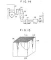
- Figs. 14 and 15 attached hereto show a conventional dry smoke denitrating apparatus for treating an exhaust gas from a coal-fired boiler, which technique is disclosed in Japanese Patent Application No. 024539/1982.
- an exhaust gas is delivered from a boiler 01 through an economizer 02 and a flue 03 to a denitration reactor 05, and on the way an NH 3 gas for denitration reaction is injected through a gas injection inlet 04 into the exhaust gas streaming through the flue 03.
- the exhaust gas passes through a gas parallel flow type catalyst section 06 in the denitration reactor 05, the component NO,, in the exhaust gas is decomposed into nitrogen and water.
- the exhaust gas passes through an air heater 07, an electric dust collector 08 and an exhaust gas blower 09, and is then discharged from the system through a chimney 010 into the atmosphere.
- Fig. 15 shows a detailed perspective view of a conventional gas parallel flow type catalyst section 06 disposed in the denitration reactor 05.
- reference numeral 011 is an inlet exhaust gas
- numeral 012 is an outlet exhaust gas
- 013 is a lattice catalyst
- 014 is a package which is packed with the plurality of catalysts 013.
- the dust sticks to and accumulates on the edge portions of the catalysts on the gas inlet side and the inlet peripheries of gas passage holes of the catalysts in the gas parallel flow type catalyst section, and finally the gas passage holes will be narrowed and some of the holes will be clogged with the dust.
- the dust sticks to or accumulates on the surfaces of the catalysts in the catalyst section through which the gas passes. This fact will lead to the increase in a pressure loss in the reactor and the decline in an activity of the catalysts, so that the operation of the apparatus will be impossible.
- a dust remover i.e., a suit blow device is equipped in the apparatus.
- a gas can be jetted from a gas inlet side or a gas outlet side of the catalyst section in order to remove the accumulated dust therefrom.
- the dust on the catalyst end surfaces on the inlet side of the catalyst section and on the inlet peripheries of the gas passage holes in the catalysts can be removed substantially perfectly therefrom.
- the dust on the surfaces of the catalysts in the catalyst section cannot be eliminated effectively therefrom even by the above means, so that it is possible to prevent the activity of the catalysts from deteriorating owing to the dust on the catalyst surfaces, though the increase in the pressure loss can be inhibited.
- An object of the present invention is to solve these problems of the above conventional method and apparatus.
- an apparatus of the present invention is characterized by additionally including a dust collision device disposed on the gas inlet side, i.e., on the upstream side of a parallel flow type catalyst section.
- Table 1 sets forth exemplary analytical values of main components of fly ashes as well as alkaline earth metals and alkaline metals concerned with a stickiness which are contained an exhaust gases from a coal-fired boiler.
- the fly ash A is that which has been obtained from an exhaust gas of a usual coal (which is chiefly composed of bituminous coal) often used recently in industrial boilers in Japan
- the fly ash B is that which has been obtained from an exhaust gas of a poor material called lignite.
- the main components are Si0 2 and AI z 0 3 .
- concentrations of the alkaline earth metal oxides and the alkaline metal oxides such as CaO, MgO, K 2 0 and Na 2 0 concerned with the stickiness are relatively low, but with regard to the fly ash B, CaO of these components is contained therein at a particularly high concentration.
- the fly ash does not stick to the catalyst surfaces, though it collides with the catalyst surfaces in the reactor. Further, the alkaline metal oxides and the alkaline earth metal oxides in the fly ash scarcely stick to the catalyst surfaces, and rather the catalyst surfaces are worn by an impact force at the time of the collision of the fly ash. Therefore, any particular problem regarding performance is not present herein.
- each of these glassy fine grains is several tens of microns in average diametsr, and therefore an impact force of each grain against the catalyst surface is great to some extent.
- the shock of the collision is not so strong as to wear the catalyst surfaces and to release the previously sticked grains therefrom.
- the glassy grains are characteristically liable to stick to the catalyst surfaces. If the catalyst surfaces are soiled with such a material consisting principally of CaO, the diffusion of the gas into the catalysts will be disturbed and the activity of the catalysts will be lost gradually.
- the inventors of the present patent have contemplated that the soft material consisting principally of CaO around the fly ash grains is separated, as perfectly as possible, from the glassy material consisting principally of the Si0 2 -AI 2 0 3 compound in the fly ash grains, and the separated materials are carried on an exhaust gas toward the conventional gas parallel flow type catalytic reactor.
- peripheral CaO material can be separated from the core glassy material by forcing the fly ash to collide with the surfaces of solid collision plates disposed on the upstream side of the catalyst section.
- the grains even if the grains have sticked on the surfaces, they will be released therefrom by means of an impact force, when the Si0 2 -AI z 0 3 glassy fly ash grains having hard surfaces collide with the catalyst surfaces. As a result, the catalyst surfaces are scarcely contaminated with the sticked grains, which effect permits maintaining a performance of the catalysts stably for a long period of time.
- a fly ash 16 of the kind B in Table 1 was uniformly dispersed in an air flow 15, was then forced to collide with metal collision plates 17, was treated by a bag filter 18, and was at last collected as a fly ash 19.
- the step number of the metal collision plates 17 is variable and can be selected arbitrarily.
- Degrees of a separation between the glassy material and the CaO material were estimated by first separating the fly ash 19 on the basis of grain diameters, and then chemically analyzing the separated fly ashes and comparing enlarged electron microscope photographs thereof. The obtained results are set forth in Table 2 given below.
- Table 3 sets forth conditions for the test by the apparatus in Fig. 2, and Table 4 set forth conditions for the catalyst activity test.
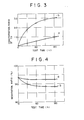
- Fig. 3 shows the results of the measured X-ray intensity of Ca on the catalyst surfaces, and they are indicated by a ratio of b to a which will be described hereinafter.
- Fig. 4 shows the results of the catalyst activity test.
- the line a represents the results of the contamination test regarding the fly ash which was treated in the above paragraph (1)
- the line b represents those of the contamination test regarding the untreated fly ash.
- test results of the lines a and b indicate that the collision treatment of the fly ash is very effective to prevent the catalyst surfaces from soiling on the downstream side of the collision treatment process.
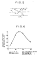
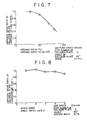
- Fig. 5 shows an arrangement state and a size of the collision plates 17 in Fig. 1. Atest was carried out by feeding the fly ash 16 and by altering an inclination angle 6 within the range of 0 to 90°. A maximum value of a collision efficiency of the fly ash was decided as an optimum value, and this collision efficiency was regarded as the indicator of an abrasion wear on the collision plate 17. The obtained test results are set forth in Fig. 6. They indicate that when the inclination angle of the collision plates is 45°, the collision efficiency is at the maximum level, and a desirable inclination angle is within the range of about 30° to about 60°.
- Figs. 1 and 5 the two steps of collision plates 17 were disposed in the air flow path 15, an opening ratio (11/12x100) of the collision plate 17 was altered within the range of 30 to 80%, and the fly ash 16 was fed, whereby the optimum value was sought, regarding the abrasion wear of the collision plate 17 as the indicator of the collision efficiency.
- Fig. 7 shows the test results. It is apparent therefrom that the smaller the opening ratio is, the higher the collision efficiency is, but in the extent in which the opening ratio is 50% or less, the collision efficiency does change greatly. Taking the increase in a pressure loss into consideration, the opening ratio of about 50% is optimum and the opening ratio range of about 30 to about 70% is desirable.
- test results indicate that when a space ratio 1 3 /21, of the space 1 3 to the opening diameter 21, is within the range of 1/1 to 5/1, the abrasion wear ratio does not change greatly, but there is the tendency that the greater the space 1 3 is, the lower the abrasion wear ratio is, though this tendency is slight. It can be considered that the preferable space ratio 1 3 /21, is within the range of about 1 to about 4.
- the present invention has been described in reference to the coal-fired fly ash, but needless to say, the present invention is not limited to the above embodiments but can be applied to other kinds of similar sticky dust. Further, the above mentioned collision plates may be replaced with other members, in so far as they have collision surfaces.
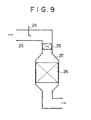
- a dust collision device 35 is disposed on the upstream side of a denitration reactor 25 so as to occupy almost all the sectional area of a duct 23.
- the dust in an exhaust gas passes through the collision device 35, they collide successively with collision plates in the collision device 35 in order to separate a sticky material on the surfaace of each dust grain therefrom, and they are then introduced into the reactor 25.
- Figs. 10(a) and 10(b) exemplarily show enlarged views of collision plates 36 in the dust collision device 35 in Fig. 9.
- the collision plates 36 consisting of plural thin steel plates alternately folded at an angle of 45°.
- Fig. 10(b) shows the collision plates 36 which are continued from the lower ends of the collision plates 36 in Fig. 10(a).
- the collision plates 36 in Fig. 10(b) are close to a gas outlet portion, and each space between the adjacent collision plates 36 is narrow so that a dust concentration in the gas outlet portion may be distributed as uniformly as possible.
- Fig. 11 there are disposed many collision members 136 each having a V-shaped surface oriented against a flow direction of the exhaust gas.
- the collision members 136 may be made from, for example, expanded metal plates over each surface of which many openings are arranged uniformly. As shown in Fig. 11, the collision plates 136 are disposed in four lines against the gas stream so that the opening sections may be alternated.
- Fig. 12 shows an embodiment using the collision members 236 the shape of which is square in the sectional view.
- other members having various shapes as in Figs. 13(a), 13(b) and 23(c) can be employed in compliance with various conditions.
- the size of the opening in each collision plate 136 is regulated os as to be equal to or larger than that of an opening in each parallel flow type catalyst (the lattice catalyst 013 in Fig. 15), which constitution can prevent the dust from accumulating on the collision plates and therefore the openings of the collision plates from being clogged therewith.
- a steel plate As a material of these collision plates (i.e., the collision plates having the V-shaped collision surfaces), a steel plate is satisfactory, but more preferable are ceramics such as mullite and the like as well as sintered metals which have suitably coarse surfaces and a wear resistance to the dust collision.
- a fly ash contained in an exhaust gas is forced to collid with a solid surface on the upstream side of a parallel flow type catalyst section, so that while streaming through the catalyst section, the fly ash does not stick to catalyst surfaces and the latter can be thereby kept clean.
- the extremely simple apparatus of the present invention permits maintaining the activity of the catalysts for a long period of time.
Landscapes
- Engineering & Computer Science (AREA)
- Chemical & Material Sciences (AREA)
- Environmental & Geological Engineering (AREA)
- Chemical Kinetics & Catalysis (AREA)
- General Chemical & Material Sciences (AREA)
- Analytical Chemistry (AREA)
- Biomedical Technology (AREA)
- Oil, Petroleum & Natural Gas (AREA)
- Health & Medical Sciences (AREA)
- Exhaust Gas Treatment By Means Of Catalyst (AREA)
- Exhaust-Gas Circulating Devices (AREA)
- Exhaust Gas After Treatment (AREA)
- Separating Particles In Gases By Inertia (AREA)
- Treating Waste Gases (AREA)
Abstract
Description
- The present invention relates to an apparatus for treating an exhaust gas in a gas parallel flow type solid-gas contact reactor. In particular, the present invention relates to a dry smoke denitrating apparatus in which a gas parallel flow type catalyst section is used and by which an exhaust gas from a coal-fired boiler is treated. The apparatus of the present invention can be applied to a system for carrying out denitration and desulfurization treatments simultaneously, another system for desulfurizing a coal-gasified gas, and other systems.
- US 40 65 918 discloses a device which should prevent plugging or clogging of an exhaust gas catalyst by dust being present in said gas. Said device consists of collision plates being disposed so as to collide with the gas flow at right angles, thereby catching dust. For a better understanding of the invention another prior art should be discussed however.
- Figs. 14 and 15 attached hereto show a conventional dry smoke denitrating apparatus for treating an exhaust gas from a coal-fired boiler, which technique is disclosed in Japanese Patent Application No. 024539/1982.
- In Fig. 14, an exhaust gas is delivered from a boiler 01 through an
economizer 02 and aflue 03 to adenitration reactor 05, and on the way an NH3 gas for denitration reaction is injected through agas injection inlet 04 into the exhaust gas streaming through theflue 03. When the exhaust gas passes through a gas parallel flowtype catalyst section 06 in thedenitration reactor 05, the component NO,, in the exhaust gas is decomposed into nitrogen and water. Afterward, the exhaust gas passes through anair heater 07, anelectric dust collector 08 and anexhaust gas blower 09, and is then discharged from the system through a chimney 010 into the atmosphere. - Fig. 15 shows a detailed perspective view of a conventional gas parallel flow
type catalyst section 06 disposed in thedenitration reactor 05. In this drawing, reference numeral 011 is an inlet exhaust gas, numeral 012 is an outlet exhaust gas, 013 is a lattice catalyst, and 014 is a package which is packed with the plurality ofcatalysts 013. - In such a catalyst section in which the plural gas parallel flow type catalysts are arranged, the gas streams along the surfaces of the catalysts. Therefore, dust flows together with the gas along the catalyst surfaces, so that a contact chance between the dust and the catalyst surfaces is low, with the result that the sticking of the dust onto the catalyst surfaces is not so perceptible.
- However, in the case that the exhaust gas containing the particularly sticky dust is treated, the dust sticks to and accumulates on the edge portions of the catalysts on the gas inlet side and the inlet peripheries of gas passage holes of the catalysts in the gas parallel flow type catalyst section, and finally the gas passage holes will be narrowed and some of the holes will be clogged with the dust. Alternatively, in some cases, the dust sticks to or accumulates on the surfaces of the catalysts in the catalyst section through which the gas passes. This fact will lead to the increase in a pressure loss in the reactor and the decline in an activity of the catalysts, so that the operation of the apparatus will be impossible.
- As a measure for the resolution of the above troubles, a dust remover, i.e., a suit blow device is equipped in the apparatus.
- When the suit blow device is used, a gas can be jetted from a gas inlet side or a gas outlet side of the catalyst section in order to remove the accumulated dust therefrom. By the use of this means, the dust on the catalyst end surfaces on the inlet side of the catalyst section and on the inlet peripheries of the gas passage holes in the catalysts can be removed substantially perfectly therefrom. However, the dust on the surfaces of the catalysts in the catalyst section cannot be eliminated effectively therefrom even by the above means, so that it is possible to prevent the activity of the catalysts from deteriorating owing to the dust on the catalyst surfaces, though the increase in the pressure loss can be inhibited.
- An object of the present invention is to solve these problems of the above conventional method and apparatus.
- That is, an apparatus of the present invention is characterized by additionally including a dust collision device disposed on the gas inlet side, i.e., on the upstream side of a parallel flow type catalyst section.
- Other objects, features and benefits of the present invention will be more elucidated from the following detailed description and drawings.
- Figs. 1 and 2 shows schematic views of test apparatuses for a method for treating an exhaust gas regarding the present invention;
- Fig. 3 shows the measured results of an X-ray strength of Ca which is stuck on the surface of catalysts after a stickiness test;
- Fig. 4 shows results of an activity test of the catalyst in Fig. 3;
- Fig. 5 shows an arrangement state and a size of collision plates in the test apparatus shown in Fig. 1;
- Fig. 6 is a diagram showing a relation between an inclination degree of the collision plate and a collision efficiency;
- Fig. 7 is a diagram showing a relation between a collision efficiency and an opening ratio (which is I,/ 12x100; 11 and 12 are in Fig. 5);
- Fig. 8 is a diagram showing a relation between a collision efficiency and a space ratio (which is 13/211; 13 and 11 are in Fig. 5);
- Fig. 9 is an exemplary schematic view of a denitration device regarding the present invention;
- Figs. 10(a) and 10(b) show enlarged sectional views of dust collection plates in Fig. 9;
- Fig. 11(a) and 11(b) show enlarged sectional views of other type dust collision plates;
- Fig. 12 shows an enlarged sectional view of other type dust collision plates;
- Figs. 13(a), (b) and (c) are plan views of other collision plates, and Figs. 13(a'), (b') and (c') are corresponding side views;
- Fig. 14 shows the whole arrangement of a conventional system in which there is disposed a dry smoke denitrating apparatus for an exhaust gas from a coal-fired boiler; and
- Fig. 15 is a detailed perspective view of a gas parallel flow type catalyst section with which a denitration reactor is packed.
- Table 1 sets forth exemplary analytical values of main components of fly ashes as well as alkaline earth metals and alkaline metals concerned with a stickiness which are contained an exhaust gases from a coal-fired boiler.

- In Table 1, the fly ash A is that which has been obtained from an exhaust gas of a usual coal (which is chiefly composed of bituminous coal) often used recently in industrial boilers in Japan, and the fly ash B is that which has been obtained from an exhaust gas of a poor material called lignite.
- In both the fly ashes, the main components are Si02 and AIz03. With regard to the fly ash A, concentrations of the alkaline earth metal oxides and the alkaline metal oxides such as CaO, MgO, K20 and Na20 concerned with the stickiness are relatively low, but with regard to the fly ash B, CaO of these components is contained therein at a particularly high concentration.
- In the fly ash A, most of the alkaline earth metal oxides and the alkaline metal oxides are dissolved in glassy fine spheres made from an SiO2/AI203 compound, and in consequence the concentrations of these metallic oxides in the surface layers of the fly ash grains are low and these grains have a relatively high hardness.
- Therefore, even when the exhaust gas formed by the combustion of such a kind of coal is treated in the conventional gas parallel flow type reactor, the fly ash does not stick to the catalyst surfaces, though it collides with the catalyst surfaces in the reactor. Further, the alkaline metal oxides and the alkaline earth metal oxides in the fly ash scarcely stick to the catalyst surfaces, and rather the catalyst surfaces are worn by an impact force at the time of the collision of the fly ash. Therefore, any particular problem regarding performance is not present herein.
- However, with regard to the fly ash B, a concentration of CaO therein is very high, and thus a relatively soft and viscous material composed chiefly of CaO surrounds glassy fine spheres comprising an SiOJAI203 compound. When caused to stream through the conventional gas parallel flow type catalyst section, such viscous fly ash grains collide with the catalyst surfaces, and at this time, part of them are forcedly pressed against the catalyst surfaces and stick thereto, so that they are left in the catalyst section.
- Each of these glassy fine grains is several tens of microns in average diametsr, and therefore an impact force of each grain against the catalyst surface is great to some extent. However, since the glassy grains are covered with the soft CaO material, the shock of the collision is not so strong as to wear the catalyst surfaces and to release the previously sticked grains therefrom. In short, it can be considered that the glassy grains are characteristically liable to stick to the catalyst surfaces. If the catalyst surfaces are soiled with such a material consisting principally of CaO, the diffusion of the gas into the catalysts will be disturbed and the activity of the catalysts will be lost gradually.
- In view of the above fact, the inventors of the present patent have contemplated that the soft material consisting principally of CaO around the fly ash grains is separated, as perfectly as possible, from the glassy material consisting principally of the Si02-AI203 compound in the fly ash grains, and the separated materials are carried on an exhaust gas toward the conventional gas parallel flow type catalytic reactor.
- Finally, the inventors have found that the peripheral CaO material can be separated from the core glassy material by forcing the fly ash to collide with the surfaces of solid collision plates disposed on the upstream side of the catalyst section.
- The thus separated grains will behave in the catalyst section, as follows:
- In the first place, the sticky grains mainly comprising CaO collide with the catalyst surfaces. Afterward, they stream on a gas flow without sticking thereto, because they are small in diameter (about several microns) and also small in mass, and because their pressurizing force against the surfaces is weak.
- Further, even if the grains have sticked on the surfaces, they will be released therefrom by means of an impact force, when the Si02-AIz03 glassy fly ash grains having hard surfaces collide with the catalyst surfaces. As a result, the catalyst surfaces are scarcely contaminated with the sticked grains, which effect permits maintaining a performance of the catalysts stably for a long period of time.
- Now, the present invention will be described in detail in accordance with embodiments.
- (1) With regard to a treating method of the fly ash B by the use of an apparatus shown in Fig. 1, investigation was conducted.
- In this apparatus, a
fly ash 16 of the kind B in Table 1 was uniformly dispersed in anair flow 15, was then forced to collide withmetal collision plates 17, was treated by abag filter 18, and was at last collected as afly ash 19. The step number of themetal collision plates 17 is variable and can be selected arbitrarily. Degrees of a separation between the glassy material and the CaO material were estimated by first separating thefly ash 19 on the basis of grain diameters, and then chemically analyzing the separated fly ashes and comparing enlarged electron microscope photographs thereof. The obtained results are set forth in Table 2 given below.
- (2) By the use of an apparatus shown in Fig. 2, a test was carried out for a contamination degree of catalyst surfaces with the fly ash which had been treated in the preceding paragraph (1) and the untreated fly ash. In this apparatus, a
fly ash 16 was dispersed in anair flow 15 and was then introduced into acatalyst section 13 having lattice catalysts which was disposed on the downstream side of the fly ash introducing position. After the test, the lattice catalysts were taken out from thecatalyst section 13 and were then subjected to a fluorescent X-ray analysis in order to inspect, as the contamination degree, an X-ray intensity which was indicative of a Ca level on the surface of the catalyst. In addition, a denitration performance was examined by the use of a catalyst activity testing device. - Table 3 sets forth conditions for the test by the apparatus in Fig. 2, and Table 4 set forth conditions for the catalyst activity test.
- Fig. 3 shows the results of the measured X-ray intensity of Ca on the catalyst surfaces, and they are indicated by a ratio of b to a which will be described hereinafter. Fig. 4 shows the results of the catalyst activity test.
- In Figs. 3 and 4, the line a represents the results of the contamination test regarding the fly ash which was treated in the above paragraph (1), and the line b represents those of the contamination test regarding the untreated fly ash.
- The test results of the lines a and b indicate that the collision treatment of the fly ash is very effective to prevent the catalyst surfaces from soiling on the downstream side of the collision treatment process.

- Fig. 5 shows an arrangement state and a size of the
collision plates 17 in Fig. 1. Atest was carried out by feeding thefly ash 16 and by altering an inclination angle 6 within the range of 0 to 90°. A maximum value of a collision efficiency of the fly ash was decided as an optimum value, and this collision efficiency was regarded as the indicator of an abrasion wear on thecollision plate 17. The obtained test results are set forth in Fig. 6. They indicate that when the inclination angle of the collision plates is 45°, the collision efficiency is at the maximum level, and a desirable inclination angle is within the range of about 30° to about 60°. - In Figs. 1 and 5, the two steps of
collision plates 17 were disposed in theair flow path 15, an opening ratio (11/12x100) of thecollision plate 17 was altered within the range of 30 to 80%, and thefly ash 16 was fed, whereby the optimum value was sought, regarding the abrasion wear of thecollision plate 17 as the indicator of the collision efficiency. - Fig. 7 shows the test results. It is apparent therefrom that the smaller the opening ratio is, the higher the collision efficiency is, but in the extent in which the opening ratio is 50% or less, the collision efficiency does change greatly. Taking the increase in a pressure loss into consideration, the opening ratio of about 50% is optimum and the opening ratio range of about 30 to about 70% is desirable.
- In Figs. 1 and 5, a
space 13 between the first step and the second step of thecollision plates 17 was altered, whereby the optimum value was sought, regarding the abrasion wear of a pair ofcollision plates 17 on the downstream side as the indicator of the collision efficiency. The obtained test results are set forth in Fig. 8. - The test results indicate that when a
space ratio 13/21, of thespace 13 to the opening diameter 21, is within the range of 1/1 to 5/1, the abrasion wear ratio does not change greatly, but there is the tendency that the greater thespace 13 is, the lower the abrasion wear ratio is, though this tendency is slight. It can be considered that thepreferable space ratio 13/21, is within the range of about 1 to about 4. - The present invention has been described in reference to the coal-fired fly ash, but needless to say, the present invention is not limited to the above embodiments but can be applied to other kinds of similar sticky dust. Further, the above mentioned collision plates may be replaced with other members, in so far as they have collision surfaces.
- (3) Next, reference will be made to an apparatus regarding the present invention.
- As shown in Fig. 9, a
dust collision device 35 is disposed on the upstream side of adenitration reactor 25 so as to occupy almost all the sectional area of aduct 23. When the dust in an exhaust gas passes through thecollision device 35, they collide successively with collision plates in thecollision device 35 in order to separate a sticky material on the surfaace of each dust grain therefrom, and they are then introduced into thereactor 25. - Figs. 10(a) and 10(b) exemplarily show enlarged views of
collision plates 36 in thedust collision device 35 in Fig. 9. In Fig. 10(a), there are arranged thecollision plates 36 consisting of plural thin steel plates alternately folded at an angle of 45°. Fig. 10(b) shows thecollision plates 36 which are continued from the lower ends of thecollision plates 36 in Fig. 10(a). Thecollision plates 36 in Fig. 10(b) are close to a gas outlet portion, and each space between theadjacent collision plates 36 is narrow so that a dust concentration in the gas outlet portion may be distributed as uniformly as possible. - In Fig. 11, there are disposed
many collision members 136 each having a V-shaped surface oriented against a flow direction of the exhaust gas. Thecollision members 136 may be made from, for example, expanded metal plates over each surface of which many openings are arranged uniformly. As shown in Fig. 11, thecollision plates 136 are disposed in four lines against the gas stream so that the opening sections may be alternated. Fig. 12 shows an embodiment using thecollision members 236 the shape of which is square in the sectional view. In addition, as the collision plates, other members having various shapes as in Figs. 13(a), 13(b) and 23(c) can be employed in compliance with various conditions. The size of the opening in eachcollision plate 136 is regulated os as to be equal to or larger than that of an opening in each parallel flow type catalyst (thelattice catalyst 013 in Fig. 15), which constitution can prevent the dust from accumulating on the collision plates and therefore the openings of the collision plates from being clogged therewith. - As a material of these collision plates (i.e., the collision plates having the V-shaped collision surfaces), a steel plate is satisfactory, but more preferable are ceramics such as mullite and the like as well as sintered metals which have suitably coarse surfaces and a wear resistance to the dust collision.
- According to the present invention just described, a fly ash contained in an exhaust gas is forced to collid with a solid surface on the upstream side of a parallel flow type catalyst section, so that while streaming through the catalyst section, the fly ash does not stick to catalyst surfaces and the latter can be thereby kept clean. In short, the extremely simple apparatus of the present invention permits maintaining the activity of the catalysts for a long period of time.
Claims (6)
Priority Applications (1)
| Application Number | Priority Date | Filing Date | Title |
|---|---|---|---|
| AT87730059T ATE59572T1 (en) | 1986-05-26 | 1987-05-19 | DEVICE FOR TREATMENT OF AN EXHAUST GAS. |
Applications Claiming Priority (2)
| Application Number | Priority Date | Filing Date | Title |
|---|---|---|---|
| JP61119072A JPS63134035A (en) | 1986-05-26 | 1986-05-26 | Treatment of exhaust gas |
| JP119072/86 | 1986-05-26 |
Publications (2)
| Publication Number | Publication Date |
|---|---|
| EP0247965A1 EP0247965A1 (en) | 1987-12-02 |
| EP0247965B1 true EP0247965B1 (en) | 1991-01-02 |
Family
ID=14752189
Family Applications (1)
| Application Number | Title | Priority Date | Filing Date |
|---|---|---|---|
| EP87730059A Expired - Lifetime EP0247965B1 (en) | 1986-05-26 | 1987-05-19 | Apparatus for treating exhaust gas |
Country Status (5)
| Country | Link |
|---|---|
| US (1) | US4857276A (en) |
| EP (1) | EP0247965B1 (en) |
| JP (1) | JPS63134035A (en) |
| AT (1) | ATE59572T1 (en) |
| DE (1) | DE3766887D1 (en) |
Families Citing this family (16)
| Publication number | Priority date | Publication date | Assignee | Title |
|---|---|---|---|---|
| FI91220C (en) * | 1992-05-21 | 1994-06-10 | Ahlstroem Oy | Method and apparatus for providing a gas lock in a return duct and / or controlling the flow of the circulating material in a circulating bed reactor |
| JP2726382B2 (en) * | 1993-12-13 | 1998-03-11 | 俊和 河合 | Design method of suction device for local ventilation |
| DE19741199C2 (en) | 1997-09-18 | 2000-10-26 | Siemens Ag | Static mixer |
| US6110247A (en) * | 1998-11-13 | 2000-08-29 | Mesosystems Technology, Inc. | Micromachined impactor pillars |
| US6120573A (en) * | 1998-11-13 | 2000-09-19 | Mesosystems Technology, Inc. | Micromachined teardrop-shaped virtual impactor |
| US6156087A (en) * | 1999-03-05 | 2000-12-05 | Lafarge Corporation | Dust collection system |
| US6749670B2 (en) | 2001-03-26 | 2004-06-15 | Shell Oil Company | Process for trapping particulate matter in hot gas and trap therefor |
| SE527104C2 (en) * | 2004-05-21 | 2005-12-20 | Alstom Technology Ltd | Method and apparatus for separating dust particles |
| US8359832B2 (en) | 2009-12-21 | 2013-01-29 | Caterpillar Inc. | SCR reductant mixer |
| JP5762255B2 (en) * | 2011-11-16 | 2015-08-12 | 三菱日立パワーシステムズ株式会社 | Exhaust gas treatment equipment |
| US10730012B2 (en) | 2014-07-25 | 2020-08-04 | Chemical and Metal Technologies LLC | Extraction of target materials using CZTS sorbent |
| WO2016014981A1 (en) * | 2014-07-25 | 2016-01-28 | Chemical and Metal Technologies LLC | Emissions contaminant capture and collection device and method of use |
| US10888836B2 (en) | 2014-07-25 | 2021-01-12 | Chemical and Metal Technologies LLC | Extraction of target materials using CZTS sorbent |
| JP7075257B2 (en) * | 2018-03-28 | 2022-05-25 | 三菱重工業株式会社 | Drying device for water to be treated and boiler system equipped with it |
| CN110185558A (en) * | 2019-05-23 | 2019-08-30 | 安徽江淮汽车集团股份有限公司 | Gas mixer and engine charge mixed structure |
| CN117482747B (en) * | 2023-12-27 | 2024-04-30 | 河南环碧环保工程设备有限公司 | System and method for treating glass kiln total oxygen kiln flue gas |
Family Cites Families (15)
| Publication number | Priority date | Publication date | Assignee | Title |
|---|---|---|---|---|
| US1044208A (en) * | 1912-05-16 | 1912-11-12 | Max Luhn | Device for purifying the steam in steam-generators. |
| US2648395A (en) * | 1951-01-30 | 1953-08-11 | Jr Harry S Pond | Air cleaner for internal-combustion engines |
| US2828818A (en) * | 1954-06-08 | 1958-04-01 | Guif Oil Corp | Method and apparatus for separation of gas from oil |
| US2793709A (en) * | 1955-03-18 | 1957-05-28 | Now Ind Inc | Filter |
| US3110581A (en) * | 1960-06-08 | 1963-11-12 | Simpson De Roy | Exhaust filter |
| US3441381A (en) * | 1965-06-22 | 1969-04-29 | Engelhard Ind Inc | Apparatus for purifying exhaust gases of an internal combustion engine |
| US3799512A (en) * | 1972-01-10 | 1974-03-26 | Echols B | Gas-liquid mixing apparatus |
| US3813855A (en) * | 1972-12-08 | 1974-06-04 | Combustion Eng | Separator |
| US4065918A (en) * | 1973-02-12 | 1978-01-03 | Ethyl Corporation | Exhaust systems |
| US3998599A (en) * | 1974-09-20 | 1976-12-21 | Gould Inc. | System for catalytic reduction of NOx emanating from an internal combustion engine |
| FR2344318A1 (en) * | 1976-03-16 | 1977-10-14 | Renault | PAINTING BOOTH INCLUDING A RECOVERY DEVICE |
| JPS5428275A (en) * | 1977-08-05 | 1979-03-02 | Hitachi Ltd | Catalyst structure in catalytic reactor |
| JPS6017217Y2 (en) * | 1980-05-19 | 1985-05-27 | 三菱重工業株式会社 | Solid-gas contact reactor |
| US4512787A (en) * | 1983-10-19 | 1985-04-23 | Mathews J Paul | Device for filtering stack gases |
| JPS61183182A (en) * | 1985-02-11 | 1986-08-15 | 株式会社デンソー | Porous ceramic structure |
-
1986
- 1986-05-26 JP JP61119072A patent/JPS63134035A/en active Pending
-
1987
- 1987-05-18 US US07/051,734 patent/US4857276A/en not_active Expired - Fee Related
- 1987-05-19 DE DE8787730059T patent/DE3766887D1/en not_active Expired - Lifetime
- 1987-05-19 AT AT87730059T patent/ATE59572T1/en active
- 1987-05-19 EP EP87730059A patent/EP0247965B1/en not_active Expired - Lifetime
Also Published As
| Publication number | Publication date |
|---|---|
| EP0247965A1 (en) | 1987-12-02 |
| JPS63134035A (en) | 1988-06-06 |
| US4857276A (en) | 1989-08-15 |
| ATE59572T1 (en) | 1991-01-15 |
| DE3766887D1 (en) | 1991-02-07 |
Similar Documents
| Publication | Publication Date | Title |
|---|---|---|
| EP0247965B1 (en) | Apparatus for treating exhaust gas | |
| US7556674B2 (en) | Method and device for the separation of dust particles | |
| EP0241310B1 (en) | Method for the dry regeneration of a catalyst | |
| TW403823B (en) | Alkaline sorbent injection for mercury control | |
| EP0540743B1 (en) | Process, apparatus and system for the treatment of flue gas | |
| CA1288705C (en) | Chevron-type mist eliminator and method | |
| US4888158A (en) | Droplet impingement device | |
| JPS5824174B2 (en) | Exhaust gas treatment method | |
| EP0172588B1 (en) | Process for separating nox and so2 from flue gases | |
| CA2168486C (en) | Particle agglomeration and precipitation from a gaseous stream | |
| DE69215252T2 (en) | Exhaust gas treatment apparatus | |
| JPH0295415A (en) | Waste gas denitration apparatus | |
| DE69522635T2 (en) | Method of operating a denitrification device for a coal-fired boiler | |
| Burtscher et al. | Efficiency of flue gas cleaning in waste incineration for submicron particles | |
| EP0029564A1 (en) | Process for separating gaseous components from a gas current, particularly a current of flue gas | |
| DE312612C (en) | ||
| GB2228880A (en) | Method and apparatus for wetting the particles contained in a gas flow | |
| DE3736912C3 (en) | Process for the denitrification of combustion gases | |
| Columbus | Series cyclone arrangements to reduce gin emissions | |
| DE10018851B4 (en) | Device for separating particles from exhaust gas from internal combustion engines | |
| Meserole et al. | Controlling trace species in the utility industry | |
| KR20190054330A (en) | Fly ash capture apparatus | |
| DE4208204C1 (en) | ||
| Paur et al. | Removal of the aerosol formed in the electron beam dry scrubbing process by bag filters | |
| DE60223947T2 (en) | METHOD FOR REMOVING NITRIC OXIDES FROM EXHAUST GASES FROM A CATALYTIC SWITCHING LAYER REACTOR |
Legal Events
| Date | Code | Title | Description |
|---|---|---|---|
| PUAI | Public reference made under article 153(3) epc to a published international application that has entered the european phase |
Free format text: ORIGINAL CODE: 0009012 |
|
| AK | Designated contracting states |
Kind code of ref document: A1 Designated state(s): AT BE DE FR GB IT NL SE |
|
| 17P | Request for examination filed |
Effective date: 19880121 |
|
| 17Q | First examination report despatched |
Effective date: 19881117 |
|
| GRAA | (expected) grant |
Free format text: ORIGINAL CODE: 0009210 |
|
| AK | Designated contracting states |
Kind code of ref document: B1 Designated state(s): AT BE DE FR GB IT NL SE |
|
| REF | Corresponds to: |
Ref document number: 59572 Country of ref document: AT Date of ref document: 19910115 Kind code of ref document: T |
|
| ET | Fr: translation filed | ||
| REF | Corresponds to: |
Ref document number: 3766887 Country of ref document: DE Date of ref document: 19910207 |
|
| ITF | It: translation for a ep patent filed | ||
| PLBE | No opposition filed within time limit |
Free format text: ORIGINAL CODE: 0009261 |
|
| STAA | Information on the status of an ep patent application or granted ep patent |
Free format text: STATUS: NO OPPOSITION FILED WITHIN TIME LIMIT |
|
| 26N | No opposition filed | ||
| EAL | Se: european patent in force in sweden |
Ref document number: 87730059.0 |
|
| PGFP | Annual fee paid to national office [announced via postgrant information from national office to epo] |
Ref country code: GB Payment date: 19950510 Year of fee payment: 9 Ref country code: FR Payment date: 19950510 Year of fee payment: 9 |
|
| PGFP | Annual fee paid to national office [announced via postgrant information from national office to epo] |
Ref country code: AT Payment date: 19950512 Year of fee payment: 9 |
|
| PGFP | Annual fee paid to national office [announced via postgrant information from national office to epo] |
Ref country code: SE Payment date: 19950517 Year of fee payment: 9 |
|
| PGFP | Annual fee paid to national office [announced via postgrant information from national office to epo] |
Ref country code: DE Payment date: 19950523 Year of fee payment: 9 |
|
| PGFP | Annual fee paid to national office [announced via postgrant information from national office to epo] |
Ref country code: NL Payment date: 19950531 Year of fee payment: 9 |
|
| PGFP | Annual fee paid to national office [announced via postgrant information from national office to epo] |
Ref country code: BE Payment date: 19950712 Year of fee payment: 9 |
|
| PG25 | Lapsed in a contracting state [announced via postgrant information from national office to epo] |
Ref country code: GB Effective date: 19960519 Ref country code: AT Effective date: 19960519 |
|
| PG25 | Lapsed in a contracting state [announced via postgrant information from national office to epo] |
Ref country code: SE Effective date: 19960520 |
|
| PG25 | Lapsed in a contracting state [announced via postgrant information from national office to epo] |
Ref country code: BE Effective date: 19960531 |
|
| BERE | Be: lapsed |
Owner name: MITSUBISHI JUKOGYO K.K. Effective date: 19960531 |
|
| PG25 | Lapsed in a contracting state [announced via postgrant information from national office to epo] |
Ref country code: NL Effective date: 19961201 |
|
| GBPC | Gb: european patent ceased through non-payment of renewal fee |
Effective date: 19960519 |
|
| PG25 | Lapsed in a contracting state [announced via postgrant information from national office to epo] |
Ref country code: FR Effective date: 19970131 |
|
| PG25 | Lapsed in a contracting state [announced via postgrant information from national office to epo] |
Ref country code: DE Effective date: 19970201 |
|
| EUG | Se: european patent has lapsed |
Ref document number: 87730059.0 |
|
| NLV4 | Nl: lapsed or anulled due to non-payment of the annual fee |
Effective date: 19961201 |
|
| REG | Reference to a national code |
Ref country code: FR Ref legal event code: ST |
|
| PG25 | Lapsed in a contracting state [announced via postgrant information from national office to epo] |
Ref country code: IT Free format text: LAPSE BECAUSE OF NON-PAYMENT OF DUE FEES Effective date: 20050519 |