EP0240882A2 - Prise protégée de déflagrations pour lignes de commande - Google Patents
Prise protégée de déflagrations pour lignes de commande Download PDFInfo
- Publication number
- EP0240882A2 EP0240882A2 EP87104643A EP87104643A EP0240882A2 EP 0240882 A2 EP0240882 A2 EP 0240882A2 EP 87104643 A EP87104643 A EP 87104643A EP 87104643 A EP87104643 A EP 87104643A EP 0240882 A2 EP0240882 A2 EP 0240882A2
- Authority
- EP
- European Patent Office
- Prior art keywords
- plug
- socket
- base body
- pins
- plate
- Prior art date
- Legal status (The legal status is an assumption and is not a legal conclusion. Google has not performed a legal analysis and makes no representation as to the accuracy of the status listed.)
- Granted
Links
Images


Classifications
-
- H—ELECTRICITY
- H01—ELECTRIC ELEMENTS
- H01R—ELECTRICALLY-CONDUCTIVE CONNECTIONS; STRUCTURAL ASSOCIATIONS OF A PLURALITY OF MUTUALLY-INSULATED ELECTRICAL CONNECTING ELEMENTS; COUPLING DEVICES; CURRENT COLLECTORS
- H01R13/00—Details of coupling devices of the kinds covered by groups H01R12/70 or H01R24/00 - H01R33/00
- H01R13/46—Bases; Cases
- H01R13/52—Dustproof, splashproof, drip-proof, waterproof, or flameproof cases
- H01R13/527—Flameproof cases
-
- H—ELECTRICITY
- H01—ELECTRIC ELEMENTS
- H01R—ELECTRICALLY-CONDUCTIVE CONNECTIONS; STRUCTURAL ASSOCIATIONS OF A PLURALITY OF MUTUALLY-INSULATED ELECTRICAL CONNECTING ELEMENTS; COUPLING DEVICES; CURRENT COLLECTORS
- H01R13/00—Details of coupling devices of the kinds covered by groups H01R12/70 or H01R24/00 - H01R33/00
- H01R13/62—Means for facilitating engagement or disengagement of coupling parts or for holding them in engagement
- H01R13/639—Additional means for holding or locking coupling parts together, after engagement, e.g. separate keylock, retainer strap
Definitions
- the invention relates to an explosion suppression or wet-g tergesehaffte gastronolige Kupnlunassteakvorriehtuna for control cables according to the preamble of claim 1.
- Explosion-proof coupling plug devices are known per se. Most of these coupling water devices are only designed for energy circuits for operational use (max. 5 pins). For this reason there is an electrical switch in the socket, with which it is achieved that the socket and the plug can only be disconnected from the power supply, so that the socket may not be surrounded by an arc drawn between the plug pins and the sockets when the coupling plug device is pulled apart explosive gas is ignited.
- the object of the invention is to provide a coupling plug device of the type mentioned at the outset, which is particularly suitable for control lines.
- the pins of the plug are loosely mounted between two plastic parts, namely the base body and the plate, the two plastic parts being designed so that they can be produced both by spraying and by turning and drilling.
- the same bracket is also suitable for the sockets; there is a base body in front of e g-see, the sockets are fixed to the means of a plate. So that the plug pins or sockets do not twist, the strips are provided with a profile; it is preferably a hexagonal profile.
- Two measures have been taken to achieve explosion and weather protection: First, the air gaps between the recesses on the base of the socket and the plug pins, and secondly, the locking of the cover on the plug, which prevents the plug from being accidentally or unauthorized by the socket can be deducted. Because a tool is required to release the lock, the plug can only be "deliberately" removed.
- a line coupling is flameproof and explosion g e-butter design from the patent application, file number S 6666 Siemens-Schuckert shares g e-society, from 04 02./22. 10.
- Became known in 1953 in which, however, the lid is not used to lock the socket to the plug-in connector, but rather a special design of a lever with an independent locking device.
- DE-GM 84 09 997 it is known to provide a nose on the cover which engages behind a nose on the plug in order to prevent the plug from being easily pulled out of the socket.
- the plug-in device described therein is not explosion-proof and, on the other hand, it is easy to lift the cover off the nose on the plug, so that there is no fixation corresponding to the explosion and / or weather protection regulations.
- fastening element can be configured can be seen from the characterizing features of claim 2.
- the cover snaps into place automatically; only the lid can only be removed using a tool.
- a screw can also be provided in accordance with the characterizing features of claim 3.
- an inner flange is provided on the collar body, which comprises the connector pins, which is clamped between the base body and the plate; as a result, the base body and plate, and thus the connector pins, are fixed on the housing of the connector. So that the base body and the plate are not against each other or against the Kra g twist eneffort, the screws pass through according to the characterizing part of claim 5 at least partially the inner flange.
- each socket element is provided with special contact bodies according to the characterizing part of claim 8, with which sparking is reliably prevented during operation.
- a further embodiment of the invention can be such that the socket elements and the plug pins have latching means with which they can be inserted into the base body and locked therein after connecting the control lines.
- the manufacturer or the customer can connect the individual plug pins to the control lines and, after this connection, which can be an Ouetsch connection, for example, insert the plug pins and the socket elements into their associated base bodies. Because of the latching means, they are then fixed in their base bodies so that they cannot be pulled out.
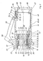
- the Kupplunassteckvortechnische is constructed from a Kupplunassteckdose 10 and a plug 11.
- the Kupplun g ssteckdose 10 has a main body 12, the plurality of recesses 13, into which sleeve elements are accommodated fourteenth
- These socket elements 14 have multi-contact elements (not shown in more detail) with which the plug pins (see below) make contact with the socket.
- a plate 17 is connected to the base body 12, through which connecting parts 18 reach to the socket elements 14. Control lines assigned to the plug device or the socket can be connected to these connecting parts 18.
- the bores 19 through which the connecting parts 18 pass are g on the round body side surrounded by a circumferential recess 20 which receives a projection 21 on a filler 22, which filler 22 is pressed against the bar 15, so that between the plate 17, the base body 12, the individual sockets 14 are fixed by means of the filler 22.
- a plurality of screws 23 are provided which are evenly distributed over the circumference.
- a plate edge 24 is formed on the plate 17, which is followed by a flange edge 25; further components of the socket can be integrally formed on this flange edge 25 in order to complement it into a uniform part (not shown in more detail).
- the plug 11 has a base body 30 to which a plate 31 is fastened by means of a screw connection 32.
- a plate 31 is fastened by means of a screw connection 32.
- profiled recesses 33 are provided, into which strips 34 on plug pins 35 are inserted.
- the strips 34 are clamped between the plate 31 and the base body 30, whereby the connector pins 35 are axially fixed.
- the strip 34 of each connector pin 35 is profiled, in the same way as the strip 15, which prevents the connector pins from rotating about their longitudinal axis.
- the base body 30 and plate 31 For fixing of the base body 30 and plate 31 in Stekker 11 has the main body 30 in the region of the parting line or parting plane between the main body 30 and the plate 31 has a circumferential external groove 36. Further, the connector 11 has a Kra g eneffort 37, on its inner surface a flange-like projection 38 is integrally formed, which engages in the outer groove 36 between the base body 30 and the plate 31. This inner flange 38 is fixed in the outer groove 36 between the base body 30 and the plate 31 by means of the screws 32.
- the collar body 37 surrounds the plug pins 35 and it has at its free end a radially outwardly projecting nose 38 which, when the plug 11 is inserted into the socket 10, passes through a groove 39 on a socket body 40 connected to the flange 25 when inserted, until an outer flange 41 formed on the collar body 37 in the area of the inner flange 38 strikes the socket or on the body 40.
- the nose 38 which slides in the groove 39, serves to guide the plug 11 relative to the socket 12, so that this ensures correct assignment of the plug pins to the associated plug sockets or socket elements.
- a connector housing 63 connects that surrounds the connection points of the control lines on the connector pins or on the connecting parts 42 reaching through the base body.
- the housing is fixed to a strain relief device (see below) by means of screw-nut connections 65 (only shown symbolically).
- the base body 30 has a notch groove 43 on its outer edge, the width of which corresponds in the circumferential direction to the width of a strain relief bracket 44.
- This strain relief having one end, a L-förmi- g e angled portion 45 which engages in a groove 46 on the base body 30 at its, so that between the inner surface of the collar body 37, the inner surface of the notch 43 and the interior of the recess or the Groove 46, the end of the strain relief bracket 44 provided with the L-shaped bend 45 is guided and held.
- the ent g e-genfede free end of the Ceientlastungsbügels 44 has also an L-shaped bend 47, at the by means of a preferably a rivet connection 48 a support plate 49 for the strain relief of the control lines is led to the connecting parts 42 of the plug pins 35.
- the support plate 49 has a bore, not shown, with an internal thread through which the screw of the screw-nut connection 65 can be screwed or screwed.
- a further screw-nut connection 66 is provided diametrically opposite, so that the connector housing 63 can be screwed symmetrically onto the support plate 49.
- strain relief bracket 44 is only loosely inserted, which considerably simplifies the assembly.
- control cables or control lines are connected to the connecting parts 42, preferably crimped on.
- control lines can also be attached to the connecting parts 18 by squeezing; then, when used as a coupling socket, a strain relief bracket like that according to reference number 44 is also required for the plug 11. It is also possible to choose such sockets in which the cables are fixed to the sockets by means of clamp connections. The prerequisite for this is, of course, that the connection between the control lines and the plug sockets is permanent and does not decrease in contact pressure. The same naturally also applies to the electrically galvanic connection between the plug sockets and the plug pins 14 and 35; the latter compound is carried out with inserted into the connector sockets 14 MultiANDverbindun g s.
- the plug device according to the invention is such a plug device in which there is no operational interruption.
- This is just a kind of separating device that is opened once or twice a year by special experts. Accordingly, a screw is thus not suddenly drawn through unverher g ESE hene chances of the plug from the socket, is provided, which connects the plug and the socket and will ensure that both can not be readily separated.
- a joint indicated at 50 is provided on the can body 40, to which a cover 60 is articulated. This cover 60 serves to cover the socket elements when the plug is pulled out.
- the lid Diametrically opposite the hinge, the lid has a lug 61, and in a corresponding distances from the left g now has free edge of the male housing 63, a groove 62 or a recess 62, reaching into the plug inserted in the nose 61 of the lid 60th
- a screw 64 By means of a screw 64 the lid 61 is then held in the groove 62; the screw 64 is screwed into a threaded bore on the connector housing 63.
- a further advantageous embodiment is as follows: On the base body 12 of the socket 10 there are recesses 13 in which the socket contact elements 14 are accommodated. These socket contact elements 14 are completely surrounded by the base body 12 and are accessible to the right to the end face of the base body 12 through recesses or openings 51 for the plug pins 35.
- the dimensions of these recesses or öff- now g s 51 can be selected such that between the outer surface of each connector pin 35 and the inner surface of each opening 51 a flameproof air gap 52 is present.
- the interior or the recess 13, in which the socket elements 14 are accommodated, which also have gap dimensions is practically pressure-tight encapsulated when the plug is inserted into the socket.
- the interior 13 is encapsulated so that it is flame-proof and thus pressure-resistant.
- the plug pins 35 or passing these plug pins 35 through the openings 51, the interior 13 is encapsulated so that it is flame-proof and thus pressure-resistant.
- Another advantageous embodiment consists in providing locking elements in the form of locking springs and locking lugs on the bushing elements 14, with which the bushing elements 14 can be locked in the interior 13. This makes it easy way to connect to the control lines, the socket members 14 and after a successful connection of the control lines, the female elements into the interior of the body 12 mitigatehe- g s. In the same way this is of course also possible with the connector pins 35.
- FIG. 2 a further embodiment of the inventions is illustrated dun g.
- This embodiment differs from the embodiment according to FIG. 1 only in that the Bracket of the cover on the connector body is modified as follows.
- the cover 60 has an end provided with a nose 70, a groove 71 being provided on the perpendicular surface line of the cover 60 which does not completely overlap the surface line, but rather leaves a nose-like projection 72 free. Behind this nose-like lead 72 engages a bolt 73 which is formed in a cavity 74 on the plug and projects through an opening 75 through to the cover.
- the socket is rectangular in cross section, so that a contact bushing 82 is to be provided which surrounds the bolt behind the bar 77 and serves to guide the helical compression spring 76. So that this socket can be used as an abutment for the helical compression spring 76, the socket has a flanged edge 83.
- the recess 74 is closed to the right, that is to the free end of the plug housing 63 by means of a cover plate 84 and to the projection 81 by means of screws 85 and 86 attached.
- the cover plate or plate 84 contains an opening 87 through which the right end of the latch extends.
- the groove 71 on the cover 60 is formed on a projection 88 (not shown in FIG. 2) and the groove 71 is delimited downwards by the nose 72.
- the plug device of the invention is g is not made such a plug-in device, with an operational interruption Chun.
- This is just a kind of separating device that is opened once or twice a year by special experts. Accordingly, so that the plug is not suddenly pulled out of the socket due to unforeseen coincidences, the screw or lock is provided which connects the plug and the socket and which produces that the two cannot be easily separated.
- the screw is provided in a manner not shown on the cover, which is articulated on a joint of the socket body 40 indicated at 50, whereas the lock sits on the connector housing.
Landscapes
- Connector Housings Or Holding Contact Members (AREA)
- Details Of Connecting Devices For Male And Female Coupling (AREA)
Applications Claiming Priority (4)
| Application Number | Priority Date | Filing Date | Title |
|---|---|---|---|
| DE3611500 | 1986-04-05 | ||
| DE3611500 | 1986-04-05 | ||
| DE19863643093 DE3643093A1 (de) | 1986-04-05 | 1986-12-17 | Explosions- bzw. schlagwettergeschuetzte kupplungssteckvorrichtung fuer steuerleitungen |
| DE3643093 | 1986-12-17 |
Publications (3)
| Publication Number | Publication Date |
|---|---|
| EP0240882A2 true EP0240882A2 (fr) | 1987-10-14 |
| EP0240882A3 EP0240882A3 (en) | 1989-02-01 |
| EP0240882B1 EP0240882B1 (fr) | 1992-10-14 |
Family
ID=25842667
Family Applications (1)
| Application Number | Title | Priority Date | Filing Date |
|---|---|---|---|
| EP87104643A Expired - Lifetime EP0240882B1 (fr) | 1986-04-05 | 1987-03-28 | Prise protégée de déflagrations pour lignes de commande |
Country Status (2)
| Country | Link |
|---|---|
| EP (1) | EP0240882B1 (fr) |
| DE (2) | DE3643093A1 (fr) |
Families Citing this family (2)
| Publication number | Priority date | Publication date | Assignee | Title |
|---|---|---|---|---|
| DE20013819U1 (de) | 2000-08-10 | 2001-12-20 | CEAG Sicherheitstechnik GmbH, 59494 Soest | Explosionsgeschützte Verbindungsvorrichtung |
| CN115395305A (zh) * | 2022-08-30 | 2022-11-25 | 苏州贝尔特光伏电子科技有限公司 | 一种具有免脱落结构智能光伏连接器 |
Family Cites Families (8)
| Publication number | Priority date | Publication date | Assignee | Title |
|---|---|---|---|---|
| NL79371C (fr) * | 1952-03-05 | |||
| DE1045507B (de) * | 1955-03-31 | 1958-12-04 | Plessey Co Ltd | Elektrische Kupplung zur Verbindung mehradriger Kabelsysteme |
| GB1063077A (en) * | 1963-01-25 | 1967-03-30 | Plessey Uk Ltd | Improvements in or relating to plug-and-socket type connectors |
| DE1912825A1 (de) * | 1969-03-13 | 1970-10-01 | Amp Gmbh Fuer Loetfreie Anschl | Verbinderblock fuer elektrische Steckverbinder |
| US4061407A (en) * | 1976-03-18 | 1977-12-06 | Samuel Moore And Company | Electrical connector assembly |
| DE3221111C2 (de) * | 1982-06-04 | 1986-01-02 | Brown, Boveri & Cie Ag, 6800 Mannheim | Explosions- oder schlagwettergeschützte elektrische Kupplungssteckvorrichtung |
| US4628392A (en) * | 1983-12-20 | 1986-12-09 | Biw Cable Systems, Inc. | Explosion proof electrical connector system with quick power disconnect |
| DE8409997U1 (de) * | 1984-03-31 | 1984-06-28 | Elektro-Bals, 5942 Kirchhundem | Abschließbare CEE-Rundsteckvorrichtung |
-
1986
- 1986-12-17 DE DE19863643093 patent/DE3643093A1/de not_active Withdrawn
-
1987
- 1987-03-28 DE DE8787104643T patent/DE3782181D1/de not_active Expired - Lifetime
- 1987-03-28 EP EP87104643A patent/EP0240882B1/fr not_active Expired - Lifetime
Also Published As
| Publication number | Publication date |
|---|---|
| EP0240882B1 (fr) | 1992-10-14 |
| EP0240882A3 (en) | 1989-02-01 |
| DE3782181D1 (de) | 1992-11-19 |
| DE3643093A1 (de) | 1987-10-08 |
Similar Documents
| Publication | Publication Date | Title |
|---|---|---|
| EP1925060B1 (fr) | Connecteur a fiche antideflagrant | |
| EP0667046B1 (fr) | Connecteur blinde avec raccord de cable | |
| DE4437818C2 (de) | Stecker für den Anschluß an das abisolierte Ende eines Herzelektroden-Drahtes | |
| DE3726778C2 (fr) | ||
| DE2320981C2 (de) | Steckdose zur Aufnahme eines Stromschienenadapters | |
| EP0444478A1 (fr) | Porte-contact pour prise de courant ou connecteur pour le raccordement de remorques de véhicules | |
| EP0240882B1 (fr) | Prise protégée de déflagrations pour lignes de commande | |
| DE69728326T2 (de) | L-förmige Lampenfassung | |
| EP0254226B1 (fr) | Combinaison de fiche et de prise pour la connexion de lampes et d'appareils électriques | |
| EP0647988A1 (fr) | Connecteur à broche | |
| DE3221111C2 (de) | Explosions- oder schlagwettergeschützte elektrische Kupplungssteckvorrichtung | |
| DE3220839A1 (de) | Explosions- oder schlagwettergeschuetzte steckvorrichtung | |
| EP0344628A1 (fr) | Douille antidéflagrante pour 2 broches-tubes fluorescents | |
| DE2918784C2 (de) | Berührungsschutz für die Kontaktstücke eines Vielfachsteckverbinders | |
| DE8609258U1 (de) | Kupplungssteckvorrichtung für Steuerleitungen | |
| DE9207738U1 (de) | Mit einem Schutzleiterkontakt ausgestatteter elektrischer Stecker | |
| CH712682A2 (de) | Elektrisches Installationsgerät. | |
| WO2006010292A1 (fr) | Bloc d'alimentation et chargeur | |
| DE3919219C1 (fr) | ||
| DE4118637A1 (de) | Elektrische kupplung | |
| EP0471817B1 (fr) | Dispositif de connexion electrique pour minuterie de contact enfichable | |
| DE29615140U1 (de) | Einpolige Laststeckverbinderkombination | |
| EP0159505A2 (fr) | Dispositif de connexion à fiche avec une protection contre les explosions | |
| DE3011762C2 (de) | Mehrpolige Kragensteckvorrichtung | |
| DE3608589A1 (de) | Steckverbindergehaeuse |
Legal Events
| Date | Code | Title | Description |
|---|---|---|---|
| PUAI | Public reference made under article 153(3) epc to a published international application that has entered the european phase |
Free format text: ORIGINAL CODE: 0009012 |
|
| AK | Designated contracting states |
Kind code of ref document: A2 Designated state(s): DE FR GB |
|
| RAP1 | Party data changed (applicant data changed or rights of an application transferred) |
Owner name: ASEA BROWN BOVERI AKTIENGESELLSCHAFT |
|
| PUAL | Search report despatched |
Free format text: ORIGINAL CODE: 0009013 |
|
| AK | Designated contracting states |
Kind code of ref document: A3 Designated state(s): DE FR GB |
|
| 17P | Request for examination filed |
Effective date: 19890316 |
|
| 17Q | First examination report despatched |
Effective date: 19910618 |
|
| GRAA | (expected) grant |
Free format text: ORIGINAL CODE: 0009210 |
|
| AK | Designated contracting states |
Kind code of ref document: B1 Designated state(s): DE FR GB |
|
| REF | Corresponds to: |
Ref document number: 3782181 Country of ref document: DE Date of ref document: 19921119 |
|
| GBT | Gb: translation of ep patent filed (gb section 77(6)(a)/1977) |
Effective date: 19921202 |
|
| ET | Fr: translation filed | ||
| PLBI | Opposition filed |
Free format text: ORIGINAL CODE: 0009260 |
|
| 26 | Opposition filed |
Opponent name: SIEMENS AKTIENGESELLSCHAFT, BERLIN UND MUENCHEN Effective date: 19930217 |
|
| PLBN | Opposition rejected |
Free format text: ORIGINAL CODE: 0009273 |
|
| STAA | Information on the status of an ep patent application or granted ep patent |
Free format text: STATUS: OPPOSITION REJECTED |
|
| 27O | Opposition rejected |
Effective date: 19941216 |
|
| REG | Reference to a national code |
Ref country code: GB Ref legal event code: 732E |
|
| REG | Reference to a national code |
Ref country code: FR Ref legal event code: TP |
|
| REG | Reference to a national code |
Ref country code: GB Ref legal event code: IF02 |
|
| PGFP | Annual fee paid to national office [announced via postgrant information from national office to epo] |
Ref country code: GB Payment date: 20020205 Year of fee payment: 16 |
|
| PGFP | Annual fee paid to national office [announced via postgrant information from national office to epo] |
Ref country code: FR Payment date: 20020228 Year of fee payment: 16 |
|
| PG25 | Lapsed in a contracting state [announced via postgrant information from national office to epo] |
Ref country code: GB Free format text: LAPSE BECAUSE OF NON-PAYMENT OF DUE FEES Effective date: 20030328 |
|
| GBPC | Gb: european patent ceased through non-payment of renewal fee |
Effective date: 20030328 |
|
| PG25 | Lapsed in a contracting state [announced via postgrant information from national office to epo] |
Ref country code: FR Free format text: LAPSE BECAUSE OF NON-PAYMENT OF DUE FEES Effective date: 20031127 |
|
| REG | Reference to a national code |
Ref country code: FR Ref legal event code: ST |
|
| PGFP | Annual fee paid to national office [announced via postgrant information from national office to epo] |
Ref country code: DE Payment date: 20060330 Year of fee payment: 20 |