EP0240882A2 - Explosion and flame proof plug and socket coupling for control leads - Google Patents
Explosion and flame proof plug and socket coupling for control leads Download PDFInfo
- Publication number
- EP0240882A2 EP0240882A2 EP87104643A EP87104643A EP0240882A2 EP 0240882 A2 EP0240882 A2 EP 0240882A2 EP 87104643 A EP87104643 A EP 87104643A EP 87104643 A EP87104643 A EP 87104643A EP 0240882 A2 EP0240882 A2 EP 0240882A2
- Authority
- EP
- European Patent Office
- Prior art keywords
- plug
- socket
- base body
- pins
- plate
- Prior art date
- Legal status (The legal status is an assumption and is not a legal conclusion. Google has not performed a legal analysis and makes no representation as to the accuracy of the status listed.)
- Granted
Links
Images


Classifications
-
- H—ELECTRICITY
- H01—ELECTRIC ELEMENTS
- H01R—ELECTRICALLY-CONDUCTIVE CONNECTIONS; STRUCTURAL ASSOCIATIONS OF A PLURALITY OF MUTUALLY-INSULATED ELECTRICAL CONNECTING ELEMENTS; COUPLING DEVICES; CURRENT COLLECTORS
- H01R13/00—Details of coupling devices of the kinds covered by groups H01R12/70 or H01R24/00 - H01R33/00
- H01R13/46—Bases; Cases
- H01R13/52—Dustproof, splashproof, drip-proof, waterproof, or flameproof cases
- H01R13/527—Flameproof cases
-
- H—ELECTRICITY
- H01—ELECTRIC ELEMENTS
- H01R—ELECTRICALLY-CONDUCTIVE CONNECTIONS; STRUCTURAL ASSOCIATIONS OF A PLURALITY OF MUTUALLY-INSULATED ELECTRICAL CONNECTING ELEMENTS; COUPLING DEVICES; CURRENT COLLECTORS
- H01R13/00—Details of coupling devices of the kinds covered by groups H01R12/70 or H01R24/00 - H01R33/00
- H01R13/62—Means for facilitating engagement or disengagement of coupling parts or for holding them in engagement
- H01R13/639—Additional means for holding or locking coupling parts together, after engagement, e.g. separate keylock, retainer strap
Definitions
- the invention relates to an explosion suppression or wet-g tergesehaffte gastronolige Kupnlunassteakvorriehtuna for control cables according to the preamble of claim 1.
- Explosion-proof coupling plug devices are known per se. Most of these coupling water devices are only designed for energy circuits for operational use (max. 5 pins). For this reason there is an electrical switch in the socket, with which it is achieved that the socket and the plug can only be disconnected from the power supply, so that the socket may not be surrounded by an arc drawn between the plug pins and the sockets when the coupling plug device is pulled apart explosive gas is ignited.
- the object of the invention is to provide a coupling plug device of the type mentioned at the outset, which is particularly suitable for control lines.
- the pins of the plug are loosely mounted between two plastic parts, namely the base body and the plate, the two plastic parts being designed so that they can be produced both by spraying and by turning and drilling.
- the same bracket is also suitable for the sockets; there is a base body in front of e g-see, the sockets are fixed to the means of a plate. So that the plug pins or sockets do not twist, the strips are provided with a profile; it is preferably a hexagonal profile.
- Two measures have been taken to achieve explosion and weather protection: First, the air gaps between the recesses on the base of the socket and the plug pins, and secondly, the locking of the cover on the plug, which prevents the plug from being accidentally or unauthorized by the socket can be deducted. Because a tool is required to release the lock, the plug can only be "deliberately" removed.
- a line coupling is flameproof and explosion g e-butter design from the patent application, file number S 6666 Siemens-Schuckert shares g e-society, from 04 02./22. 10.
- Became known in 1953 in which, however, the lid is not used to lock the socket to the plug-in connector, but rather a special design of a lever with an independent locking device.
- DE-GM 84 09 997 it is known to provide a nose on the cover which engages behind a nose on the plug in order to prevent the plug from being easily pulled out of the socket.
- the plug-in device described therein is not explosion-proof and, on the other hand, it is easy to lift the cover off the nose on the plug, so that there is no fixation corresponding to the explosion and / or weather protection regulations.
- fastening element can be configured can be seen from the characterizing features of claim 2.
- the cover snaps into place automatically; only the lid can only be removed using a tool.
- a screw can also be provided in accordance with the characterizing features of claim 3.
- an inner flange is provided on the collar body, which comprises the connector pins, which is clamped between the base body and the plate; as a result, the base body and plate, and thus the connector pins, are fixed on the housing of the connector. So that the base body and the plate are not against each other or against the Kra g twist eneffort, the screws pass through according to the characterizing part of claim 5 at least partially the inner flange.
- each socket element is provided with special contact bodies according to the characterizing part of claim 8, with which sparking is reliably prevented during operation.
- a further embodiment of the invention can be such that the socket elements and the plug pins have latching means with which they can be inserted into the base body and locked therein after connecting the control lines.
- the manufacturer or the customer can connect the individual plug pins to the control lines and, after this connection, which can be an Ouetsch connection, for example, insert the plug pins and the socket elements into their associated base bodies. Because of the latching means, they are then fixed in their base bodies so that they cannot be pulled out.
- the Kupplunassteckvortechnische is constructed from a Kupplunassteckdose 10 and a plug 11.
- the Kupplun g ssteckdose 10 has a main body 12, the plurality of recesses 13, into which sleeve elements are accommodated fourteenth
- These socket elements 14 have multi-contact elements (not shown in more detail) with which the plug pins (see below) make contact with the socket.
- a plate 17 is connected to the base body 12, through which connecting parts 18 reach to the socket elements 14. Control lines assigned to the plug device or the socket can be connected to these connecting parts 18.
- the bores 19 through which the connecting parts 18 pass are g on the round body side surrounded by a circumferential recess 20 which receives a projection 21 on a filler 22, which filler 22 is pressed against the bar 15, so that between the plate 17, the base body 12, the individual sockets 14 are fixed by means of the filler 22.
- a plurality of screws 23 are provided which are evenly distributed over the circumference.
- a plate edge 24 is formed on the plate 17, which is followed by a flange edge 25; further components of the socket can be integrally formed on this flange edge 25 in order to complement it into a uniform part (not shown in more detail).
- the plug 11 has a base body 30 to which a plate 31 is fastened by means of a screw connection 32.
- a plate 31 is fastened by means of a screw connection 32.
- profiled recesses 33 are provided, into which strips 34 on plug pins 35 are inserted.
- the strips 34 are clamped between the plate 31 and the base body 30, whereby the connector pins 35 are axially fixed.
- the strip 34 of each connector pin 35 is profiled, in the same way as the strip 15, which prevents the connector pins from rotating about their longitudinal axis.
- the base body 30 and plate 31 For fixing of the base body 30 and plate 31 in Stekker 11 has the main body 30 in the region of the parting line or parting plane between the main body 30 and the plate 31 has a circumferential external groove 36. Further, the connector 11 has a Kra g eneffort 37, on its inner surface a flange-like projection 38 is integrally formed, which engages in the outer groove 36 between the base body 30 and the plate 31. This inner flange 38 is fixed in the outer groove 36 between the base body 30 and the plate 31 by means of the screws 32.
- the collar body 37 surrounds the plug pins 35 and it has at its free end a radially outwardly projecting nose 38 which, when the plug 11 is inserted into the socket 10, passes through a groove 39 on a socket body 40 connected to the flange 25 when inserted, until an outer flange 41 formed on the collar body 37 in the area of the inner flange 38 strikes the socket or on the body 40.
- the nose 38 which slides in the groove 39, serves to guide the plug 11 relative to the socket 12, so that this ensures correct assignment of the plug pins to the associated plug sockets or socket elements.
- a connector housing 63 connects that surrounds the connection points of the control lines on the connector pins or on the connecting parts 42 reaching through the base body.
- the housing is fixed to a strain relief device (see below) by means of screw-nut connections 65 (only shown symbolically).
- the base body 30 has a notch groove 43 on its outer edge, the width of which corresponds in the circumferential direction to the width of a strain relief bracket 44.
- This strain relief having one end, a L-förmi- g e angled portion 45 which engages in a groove 46 on the base body 30 at its, so that between the inner surface of the collar body 37, the inner surface of the notch 43 and the interior of the recess or the Groove 46, the end of the strain relief bracket 44 provided with the L-shaped bend 45 is guided and held.
- the ent g e-genfede free end of the Ceientlastungsbügels 44 has also an L-shaped bend 47, at the by means of a preferably a rivet connection 48 a support plate 49 for the strain relief of the control lines is led to the connecting parts 42 of the plug pins 35.
- the support plate 49 has a bore, not shown, with an internal thread through which the screw of the screw-nut connection 65 can be screwed or screwed.
- a further screw-nut connection 66 is provided diametrically opposite, so that the connector housing 63 can be screwed symmetrically onto the support plate 49.
- strain relief bracket 44 is only loosely inserted, which considerably simplifies the assembly.
- control cables or control lines are connected to the connecting parts 42, preferably crimped on.
- control lines can also be attached to the connecting parts 18 by squeezing; then, when used as a coupling socket, a strain relief bracket like that according to reference number 44 is also required for the plug 11. It is also possible to choose such sockets in which the cables are fixed to the sockets by means of clamp connections. The prerequisite for this is, of course, that the connection between the control lines and the plug sockets is permanent and does not decrease in contact pressure. The same naturally also applies to the electrically galvanic connection between the plug sockets and the plug pins 14 and 35; the latter compound is carried out with inserted into the connector sockets 14 MultiANDverbindun g s.
- the plug device according to the invention is such a plug device in which there is no operational interruption.
- This is just a kind of separating device that is opened once or twice a year by special experts. Accordingly, a screw is thus not suddenly drawn through unverher g ESE hene chances of the plug from the socket, is provided, which connects the plug and the socket and will ensure that both can not be readily separated.
- a joint indicated at 50 is provided on the can body 40, to which a cover 60 is articulated. This cover 60 serves to cover the socket elements when the plug is pulled out.
- the lid Diametrically opposite the hinge, the lid has a lug 61, and in a corresponding distances from the left g now has free edge of the male housing 63, a groove 62 or a recess 62, reaching into the plug inserted in the nose 61 of the lid 60th
- a screw 64 By means of a screw 64 the lid 61 is then held in the groove 62; the screw 64 is screwed into a threaded bore on the connector housing 63.
- a further advantageous embodiment is as follows: On the base body 12 of the socket 10 there are recesses 13 in which the socket contact elements 14 are accommodated. These socket contact elements 14 are completely surrounded by the base body 12 and are accessible to the right to the end face of the base body 12 through recesses or openings 51 for the plug pins 35.
- the dimensions of these recesses or öff- now g s 51 can be selected such that between the outer surface of each connector pin 35 and the inner surface of each opening 51 a flameproof air gap 52 is present.
- the interior or the recess 13, in which the socket elements 14 are accommodated, which also have gap dimensions is practically pressure-tight encapsulated when the plug is inserted into the socket.
- the interior 13 is encapsulated so that it is flame-proof and thus pressure-resistant.
- the plug pins 35 or passing these plug pins 35 through the openings 51, the interior 13 is encapsulated so that it is flame-proof and thus pressure-resistant.
- Another advantageous embodiment consists in providing locking elements in the form of locking springs and locking lugs on the bushing elements 14, with which the bushing elements 14 can be locked in the interior 13. This makes it easy way to connect to the control lines, the socket members 14 and after a successful connection of the control lines, the female elements into the interior of the body 12 mitigatehe- g s. In the same way this is of course also possible with the connector pins 35.
- FIG. 2 a further embodiment of the inventions is illustrated dun g.
- This embodiment differs from the embodiment according to FIG. 1 only in that the Bracket of the cover on the connector body is modified as follows.
- the cover 60 has an end provided with a nose 70, a groove 71 being provided on the perpendicular surface line of the cover 60 which does not completely overlap the surface line, but rather leaves a nose-like projection 72 free. Behind this nose-like lead 72 engages a bolt 73 which is formed in a cavity 74 on the plug and projects through an opening 75 through to the cover.
- the socket is rectangular in cross section, so that a contact bushing 82 is to be provided which surrounds the bolt behind the bar 77 and serves to guide the helical compression spring 76. So that this socket can be used as an abutment for the helical compression spring 76, the socket has a flanged edge 83.
- the recess 74 is closed to the right, that is to the free end of the plug housing 63 by means of a cover plate 84 and to the projection 81 by means of screws 85 and 86 attached.
- the cover plate or plate 84 contains an opening 87 through which the right end of the latch extends.
- the groove 71 on the cover 60 is formed on a projection 88 (not shown in FIG. 2) and the groove 71 is delimited downwards by the nose 72.
- the plug device of the invention is g is not made such a plug-in device, with an operational interruption Chun.
- This is just a kind of separating device that is opened once or twice a year by special experts. Accordingly, so that the plug is not suddenly pulled out of the socket due to unforeseen coincidences, the screw or lock is provided which connects the plug and the socket and which produces that the two cannot be easily separated.
- the screw is provided in a manner not shown on the cover, which is articulated on a joint of the socket body 40 indicated at 50, whereas the lock sits on the connector housing.
Landscapes
- Connector Housings Or Holding Contact Members (AREA)
- Details Of Connecting Devices For Male And Female Coupling (AREA)
Abstract
Description
Die Erfindung betrifft eine explosions- bzw. schlagwet- tergesehützte vielnolige Kupnlunassteakvorriehtuna für Steuerleitungen gemäß dem Oberbegriff des Anspruches 1.The invention relates to an explosion suppression or wet-g tergesehützte vielnolige Kupnlunassteakvorriehtuna for control cables according to the preamble of claim 1.
Explosionsgeschützte Kupplungssteckvorrichtungen sind an sich bekannt. Die meisten dieser Kupplunassteekvorriehtungen sind nur für Energiekreise zum betriebsmäßigen Bedienen ausgelegt (max. 5 Stifte). Aus diesem Grunde befindet sich in der Steckdose ein elektrischer Schalter, mit dem erreicht wird, daß die Steckdose und der Stecker nur stromlos getrennt werden können, damit nicht durch einen zwischen den Steckerstiften und den Steckbuchsen beim Auseinanderziehen der Kupplungssteckvorrichtung gezogenen Lichtbogen evtl. die Steckdose umgebendes explosibles Gas gezündet wird.Explosion-proof coupling plug devices are known per se. Most of these coupling water devices are only designed for energy circuits for operational use (max. 5 pins). For this reason there is an electrical switch in the socket, with which it is achieved that the socket and the plug can only be disconnected from the power supply, so that the socket may not be surrounded by an arc drawn between the plug pins and the sockets when the coupling plug device is pulled apart explosive gas is ignited.
Aufgabe der Erfindung ist es, eine Kupnlungssteckvorrichtung der eingangs genannten Art zu schaffen, die insbesondere für Steuerleitungen geeignet ist.The object of the invention is to provide a coupling plug device of the type mentioned at the outset, which is particularly suitable for control lines.
Diese Aufgabe wird erfindungsgemäß gelöst durch die kennzeichnenden Merkmale des Anspruches 1.This object is achieved according to the invention by the characterizing features of claim 1.
Gemäß der Erfindung sind also die Stifte des Steckers zwischen zwei Kunststoffteilen, nämlich dem Grundkörper und der Platte lose gelagert, wobei die beiden Kunststoffteile so gestaltet sind, daß sie sowohl im Spritzverfahren als auch mit Drehen und Bohren herstellbar sind. Die gleiche Halterung ist auch für die Steckbuchsen geeignet; auch dort ist ein Grundkörper vorge-sehen, an dem mittels einer Platte die Steckbuchsen festgelegt sind. Damit sich die Steckerstifte bzw. Steckbuchsen nicht verdrehen, sind die Leisten mit einem Profil versehen; es ist vorzugsweise ein Seehskantnrofil. Zur Erzielung der Explosions- bzw. Schlaawettersicherheit sind zwei Maßnahmen getroffen: Einmal die Luftspalte zwischen den Ausnehmungen am Grundkörper der Steckdose und den Steckerstiften und zum anderen die Verriegelung des Deckels am Stecker, wodurch verhindert wird, daß der Stecker unbeabsichtigt bzw. unbefugt von der Steckdose abgezogen werden kann. Dadurch, daß zum Lösen der Verriegelung ein Werkzeug erforderlich ist, kann der Stecker nur "bewußt" entfernt werden.According to the invention, the pins of the plug are loosely mounted between two plastic parts, namely the base body and the plate, the two plastic parts being designed so that they can be produced both by spraying and by turning and drilling. The same bracket is also suitable for the sockets; there is a base body in front of e g-see, the sockets are fixed to the means of a plate. So that the plug pins or sockets do not twist, the strips are provided with a profile; it is preferably a hexagonal profile. Two measures have been taken to achieve explosion and weather protection: First, the air gaps between the recesses on the base of the socket and the plug pins, and secondly, the locking of the cover on the plug, which prevents the plug from being accidentally or unauthorized by the socket can be deducted. Because a tool is required to release the lock, the plug can only be "deliberately" removed.
Wie Steckerstifte innerhalb einer Steckverbindung gehal- tert werden können, zeigt die DE-OS 14 90 171; diese Steckverbindung aber ist nicht als explosionsgeschützte oder schlaawetteraeschützte Steckvorrichtung ausgebil- det, insoweit als Maßnahmen des Explosionsschutzes, wie Verdrehunessicherheit der Steckerbuchsen oder der Stekkerstifte, Maßnahmen zur Verhinderung unbeabsichtigten Herausziehens des Steckers aus der Steckdose nicht getroffen und erforderliche Luftspalte nicht vorhanden sind.As plug pins g within a plug-in connection can be tert ehal-, is shown in DE-OS 14 90 171; However, this connector is not as explosions g eschützte or schlaawetteraeschützte plug device of g ebil- det insofar as explosion protection measures, such as Verdrehunessicherheit the plug sockets or the Stekkerstifte, measures not taken of the plug from the socket for preventing unintentional withdrawal and required air gaps are not present .
Eine Leitungskupplung in schlagwetter- und explosionsge-schützter Bauart ist aus der Patentanmeldung, Aktenzeichen S 6666 der Firma Siemens-Schuckertwerke Aktienge-sellschaft, vom 04. 02./22. 10. 1953 bekanntgeworden, bei der allerdings nicht der Deckel zur Verriegelung von Steckdose zu Steckkuppluna verwendet wird, sondern eine spezielle Ausgestaltung eines Hebels mit einer eigenständigen Verriegelungsvorrichtung. Aus dem DE-GM 84 09 997 ist bekannt, am Deckel eine Nase vorzusehen, die hinter eine Nase am Stecker greift, um ein leichtes Herausziehen des Steckers aus der Steckdose zu verhindern. Einerseits ist die darin beschriebene Steckvorrichtung nicht explosionsgeschützt und zum anderen ist es ein leichtes, den Deckel von der Nase am Stecker abzuheben, so daß eine den Explosions- bzw. Schlaawetterschutzvorschriften entsprechende Fixierung nicht gegeben ist.A line coupling is flameproof and explosion g e-schützter design from the patent application, file number S 6666 Siemens-Schuckert shares g e-society, from 04 02./22. 10. Became known in 1953, in which, however, the lid is not used to lock the socket to the plug-in connector, but rather a special design of a lever with an independent locking device. From DE-GM 84 09 997 it is known to provide a nose on the cover which engages behind a nose on the plug in order to prevent the plug from being easily pulled out of the socket. On the one hand, the plug-in device described therein is not explosion-proof and, on the other hand, it is easy to lift the cover off the nose on the plug, so that there is no fixation corresponding to the explosion and / or weather protection regulations.
Wie das Befestigungselement ausgestaltet sein kann, ist den kennzeichnenden Merkmalen des Anspruches 2 zu entnehmen. Das Einrasten des Deckels erfolgt automatisch; lediglich das Herausnehmen des Deckels kann nur mittels eines Werkzeuges erfolgen. Anstatt eines solchen Befestigungs- bzw. Verriegelungselementes kann auch einfach eine Schraube gemäß kennzeichnenden Merkmalen des Anspruches 3 vorgesehen sein.How the fastening element can be configured can be seen from the characterizing features of claim 2. The cover snaps into place automatically; only the lid can only be removed using a tool. Instead of such a fastening or locking element, a screw can also be provided in accordance with the characterizing features of claim 3.
Zur Führung und Halterung von Grundkörper und Platte am Stecker ist gemäß kennzeichnendem Teil des Anspruches 4 an dem Kragenkörper, der die Steckerstifte umfaßt, ein Innenflansch vorgesehen, der zwischen dem Grundkörper und der Platte festgeklemmt ist; dadurch sind Grundkörper und Platte und damit die Steckerstifte am Gehäuse des Steckers festgelegt. Damit sich hierbei der Grundkörper und die Platte nicht gegeneinander bzw. gegen den Kragenkörper verdrehen, durchgreifen gemäß kennzeichnendem Teil des Anspruches 5 die Schrauben zumindest teilweise den Innenflansch.For guiding and holding the base body and plate on the connector, an inner flange is provided on the collar body, which comprises the connector pins, which is clamped between the base body and the plate; as a result, the base body and plate, and thus the connector pins, are fixed on the housing of the connector. So that the base body and the plate are not against each other or against the Kra g twist enkörper, the screws pass through according to the characterizing part of claim 5 at least partially the inner flange.
Zusätzlich auch ohne die Vorsehung des Luftspaltes ist gemäß kennzeichnendem Teil des Anspruches 8 jedes Buchsenelement mit speziellen Kontaktkörpern versehen, mit denen im Betrieb eine Funkenbildung sicher verhindert wird.In addition, even without the provision of the air gap, each socket element is provided with special contact bodies according to the characterizing part of claim 8, with which sparking is reliably prevented during operation.
Eine weitere Ausgestaltung der Erfindung kann dahin gehen, daß die Buchsenelemente und die Steckerstifte Rastmittel aufweisen, mit denen sie nach Anschließen der Steuerleitungen in die Grundkörper einfügbar und darin verrastbar sind. Dadurch kann der Hersteller oder der Kunde die einzelnen Steckerstifte an die Steuerleitungen anschließen und nach der Herstellung dieser Verbindung, die beispielsweise eine Ouetschverbindung sein kann, die Steckerstifte und die Buchsenelemente in ihre zugehörigen Grundkörper einfügen. Aufgrund der Rastmittel sind diese dann nicht herausziehbar in ihren Grundkörpern festgelegt.A further embodiment of the invention can be such that the socket elements and the plug pins have latching means with which they can be inserted into the base body and locked therein after connecting the control lines. As a result, the manufacturer or the customer can connect the individual plug pins to the control lines and, after this connection, which can be an Ouetsch connection, for example, insert the plug pins and the socket elements into their associated base bodies. Because of the latching means, they are then fixed in their base bodies so that they cannot be pulled out.
Damit die Steuerleitungen von den Steckerstiften nicht abgezogen werden können, befindet sich im Inneren des Steckers gemäß kennzeichnendem Teil des Anspruches 7 ein Zugentlastungsbügel.So that the control lines cannot be removed from the connector pins, there is a strain relief bracket inside the connector according to the characterizing part of claim 7.
Anhand der Zeichnung, in der zwei Ausführungsbeispiele der Erfindung dargestellt sind, soll die Erfindung näher erläutert und beschrieben werden.The invention will be explained and described in more detail with reference to the drawing, in which two exemplary embodiments of the invention are shown.
Es zeigt:
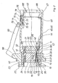
- Figur 1 eine Längsschnittansicht durch eine erfindungsgemäße Kupplungssteckvorrichtung, in gekuppeltem Zustand,
- Figur 2 eine Längsschnittansicht durch eine weitere erfindungsgemäße Kupplungssteckvorriehtung, ebenfalls in gekuppeltem Zustand,
- Figur 3 eine Längsteilschnittansicht der Verriegelung des Deckels am Stecker und
- Figur 4 eine Schnittansicht gemäß Linie IV-IV der Figur 3.
- FIG. 1 shows a longitudinal sectional view through a coupling plug device according to the invention, in the coupled state,
- FIG. 2 shows a longitudinal sectional view through a further coupling plug device according to the invention, likewise in the coupled state,
- Figure 3 is a partial longitudinal sectional view of the locking of the lid on the plug and
- Figure 4 is a sectional view taken along line IV-IV of Figure 3.
Die Kupplunassteckvorriehtung ist aufgebaut aus einer Kupplunassteckdose 10 und einem Stecker 11.The Kupplunassteckvorrichtung is constructed from a Kupplunassteckdose 10 and a
Die Kupplungssteckdose 10 besitzt einen Grundkörper 12, der mehrere Ausnehmungen 13 aufweist, in denen Buchsenelemente 14 untergebracht sind. Diese Buchsenelemente 14 besitzten nicht näher dargestellte Multikontaktelemente, mit denen die Steckerstifte (siehe weiter unten) an der Steckdose kontaktieren. An der Außenfläche jedes Buchsenelementes 14 befindet sich eine mit einem Sechskant versehene Leiste 15, die in je eine entsprechende Vertiefung 16 am Grundkörper 12 hineinpaßt. Mit dem Grundkörper 12 verbunden ist eine Platte 17, durch die Anschlußteile 18 zu den Buchsenelementen 14 hindurchgreifen. An diesen Anschlußteilen 18 können der Steckvorrichtung bzw. der Steckdose zugeordnete Steuerleitungen angeschlossen sein. Die Bohrungen 19, durch die die Anschlußteile 18 hindurchgreifen, sind grundkörperseitig von einer umlaufenden Vertiefung 20 umgeben, die einen Vorsprung 21 an einem Füllstück 22 aufnimmt, welches Füllstück 22 gegen die Leiste 15 gedrückt ist, so daß zwischen der Platte 17, dem Grundkörper 12 die einzelnen Steckbuchsen 14 mittels des Füllstückes 22 fixiert sind. Zur Verbindung der Platte 17 mit dem Grundkörper 12 sind mehrere am Umfang gleichmäßig verteilte Schrauben 23 vorgesehen.The Kupplun g ssteckdose 10 has a
An der Platte 17 ist ein Topfrand 24 angeformt, an den sich ein Flanschrand 25 anschließt; an diesen Flanschrand 25 können weitere Komponenten der Steckdose zur Ergänzung zu einem einheitlichen Teil angeformt sein (nicht näher gezeigt).A
Der Stecker 11 besitzt einen Grundkörper 30, an dem eine Platte 31 mittels einer Schraubenverbindung 32 befestigt ist. In der dem Grundkörper 30 zugewandten Seite der Platte 31 sind profilierte Vertiefungen 33 vorgesehen, in die Leisten 34 an Steckerstiften 35 eingesetzt sind. Die Leisten 34 werden dabei zwischen der Platte 31 und dem Grundkörper 30 verklemmt, wodurch die Steckerstifte 35 axial unverschieblich festgelegt sind. Die Leiste 34 jedes Steckerstiftes 35 ist profiliert, in gleicher Weise wie die Leiste 15, wodurch ein Verdrehen der Steckerstifte um ihre Längsachse verhindert ist.The
Zur Fixierung von Grundkörper 30 und Platte 31 in Stekker 11 besitzt der Grundkörper 30 im Bereich der Trennfuge bzw. Trennebene zwischen dem Grundkörper 30 und der Platte 31 eine umlaufende Außennut 36. Ferner besitzt der Stecker 11 einen Kragenkörper 37, an dessen Innenfläche ein flanschartiger Vorsprung 38 nach innen angeformt ist, der in die Außennut 36 zwischen dem Grundkörper 30 und der Platte 31 eingreift. Mittels der Schrauben 32 wird dieser Innenflansch 38 zwischen dem Grundkörper 30 und der Platte 31 in der Außennut 36 fixiert.For fixing of the
Der Kragenkörper 37 umgibt die Steckerstifte 35 und er besitzt an seinem freien Ende eine radial nach außen vorspringende Nase 38, die beim Einstecken des Steckers 11 in die Steckdose 10 durch eine Nut 39 an einem mit dem Flansch 25 verbundenen Steckdosenaußenkörper 40 beim Einschieben hindurchläuft, bis ein am Kragenkörper 37 im Bereich des Innenflansches 38 angeformter Außenflansch 41 an der Steckdose bzw. an dem Körper 40 anschlägt. Die Nase 38, die in der Nut 39 gleitet, dient zur Führung des Steckers 11 gegenüber der Steckdose 12, so daß hierdurch eine korrekte Zuordnung der Steckerstifte zu den zugehörigen Steckerbuchsen bzw. Buchsenelementen sichergestellt ist.The
An dem Außenflansch 41 schließt ein Steckergehäuse 63 an, daß die Anschlußstellen der Steuerleitungen an den Steckerstiften bzw. an den den Grundkörper durchgreifenden Anschlußteilen 42 umgibt. Mittels Schrauben-Mutter-Verbindungen 65 (lediglieh symbolisch dargestellt) wird das Gehäuse an einer Zugentlastungseinrichtung (siehe weiter unten) festgelegt.On the
Der Grundkörper 30 besitzt an seinem Außenrand eine Kerbnut 43, deren Breite in Umfangsrichtung der Breite eines Zugentlastungsbügels 44 entspricht. Dieser Zugentlastungsbügel besitzt an seinem einen Ende eine L-förmi- ge Abwinkelung 45, die in eine Nut 46 an dem Grundkörper 30 eingreift, so daß zwischen der Innenfläche des Kragenkörpers 37, der Innenfläche der Kerbe 43 und dem Innenraum der Vertiefung bzw. der Nut 46 das mit der L-förmigen Abwinkelung 45 versehene Ende des. Zugentlastungsbügels 44 geführt und festgehalten ist. Das entge-gengesetzte freie Ende des Zugentlastungsbügels 44 besitzt ebenfalls eine L-förmige Abwinkelung 47, an der mittels einer vorzugsweise eine Nietverbindung 48 eine Tragplatte 49 für die Zugentlastung der Steuerleitungen zu den Anschlußteilen 42 der Steckerstifte 35 hingeführt ist.The
Die Tragplatte 49 besitzt eine nicht mehr dargestellte Bohrung mit einem Innengewinde, durch das die Schraube der Schrauben-Muttern-Verbindunz 65 hindurchgeschraubt bzw. eingeschraubt werden kann. Diametral gegenüberliegend ist eine weitere Schrauben-Muttern-Verbindung 66 vorgesehen, damit das Steckergehäuse 63 symetrisch an der Tragplatte 49 angeschraubt werden kann.The
Ebenso wie die einzelnen Steckerstifte ist auch der Zugentlastungsbüeel 44 nur lose eingelegt, wodurch die Montage erheblich vereinfacht ist.Like the individual connector pins, the strain relief bracket 44 is only loosely inserted, which considerably simplifies the assembly.
Auf der Zugentlastunasbügelseite werden die Steuerkabel bzw. Steuerleitungen an die Anschlußteile 42 angesehlossen, vorzugsweise angequetscht.On the strain relief side, the control cables or control lines are connected to the connecting
Das Anbringen der Steuerleitungen an den Anschlußteilen 18 kann ebenfalls durch Quetschen erfolgen; dann ist bei Verwendung als Kupplungsdose auch ein Zugentlastungsbügel wie derjenige gemäß Bezugsziffer 44 für den Stecker 11 erforderlich. Es besteht auch die Möglichkeit, solche Steckbuchsen zu wählen, bei denen die Kabel mittels Klemmverbindungen zugentlastet an den Steckerbuchsen festgelegt sind. Voraussetzung hierfür ist natürlich, daß die Verbindung zwischen den Steuerleitungen und den Steckerbuchsen dauerhaft und im Kontaktdruck nicht nachlassend ausgebildet ist. Das gleiche gilt natürlich auch für die elektrisch galvanische Verbindung zwischen den Steckerbuchsen und den Steckerstiften 14 bzw. 35; die letztere Verbindung erfolgt mit in den Steckerbuchsen 14 eingesetzten Multikontaktverbindungen.The control lines can also be attached to the connecting
Da weder in der Steckdose noch im Stecker ein Schaltgerät untergebracht ist, besteht die Vorschrift, daß kun- denseitig ein externer Schalter betätigt werden muß. Natürlich könnte der Schalter bei Bedarf auch in der Dose untergebracht werden; dies ist aber aus KostengrOnden vermieden.Since neither in the socket, a switching device is still housed in the plug, there is a requirement that customer-denseiti g an external switch has to be actuated. Of course, the switch could also be accommodated in the box if required; but this is avoided for cost g rounds.
Die erfindungsgemäße Steckvorrichtung ist eine solche Steckvorrichtung, bei der eine betriebsmäßige Unterbrechung nicht erfolgt. Es handelt sich hierbei lediglich um eine Art Trennvorrichtung, die ein- oder zweimal im Jahr geöffnet wird und zwar durch besondere Fachleute. Demgemäß ist, damit nicht plötzlich durch unverhergese- hene Zufälle der Stecker aus der Steckdose gezogen wird, eine Schraube vorgesehen, die den Stecker und die Steckdose verbindet und die sicherstellt, daß beide nicht ohne weiteres getrennt werden können. Zu diesem Zweck ist am Dosenkörper 40 ein bei 50 angedeutetes Gelenk vorgesehen, an dem ein Deckel 60 angelenkt ist. Dieser Deckel 60 dient zum Abdecken der Buchsenelemente bei herausgezogenem Stecker. Diametral dem Gelenk gegenüber besitzt der Deckel eine Nase 61, und in entsprechender Entfer- nung vom linken freien Rand besitzt das Steckergehäuse 63 eine Nut 62 bzw. eine Vertiefung 62, in die bei eingeschobenem Stecker die Nase 61 des Deckels 60 hineingreift. Mittels einer Schraube 64 wird dann der Deckel mit seiner Nase 61 in der Nut 62 festgehalten; die Schraube 64 wird dabei in eine Gewindebohrung am Stekkergehäuse 63 eingeschraubt.The plug device according to the invention is such a plug device in which there is no operational interruption. This is just a kind of separating device that is opened once or twice a year by special experts. Accordingly, a screw is thus not suddenly drawn through unverher g ESE hene chances of the plug from the socket, is provided, which connects the plug and the socket and will ensure that both can not be readily separated. For this purpose, a joint indicated at 50 is provided on the
Eine weitere vorteilhafte Ausgestaltung ist folgendes: An dem Grundkörper 12 der Steckdose 10 befinden sich Ausnehmungen 13, in denen die Buchsenkontaktelemente 14 untergebracht sind. Diese Buchsenkontaktelemente 14 sind vollständig von dem Grundkörper 12 umgeben und sind nach rechts zu der Stirnseite des Grundkörpers 12 durch Ausnehmungen bzw. Öffnungen 51 für die Steckerstifte 35 zugänglich. Die Abmessungen dieser Ausnehmungen bzw. öff- nungen 51 können so gewählt werden, daß zwischen der Außenfläche jedes Steckerstiftes 35 und der Innenfläche jeder Öffnung 51 ein zünddurchschlagsicherer Luftspalt 52 vorhanden ist. Dadurch ist der Innenraum bzw. die Ausnehmung 13, in der die Buchsenelemente 14 untergebracht sind, welche ebenfalls Spaltmaße besitzen, praktisch druckfest gekapselt, wenn der Stecker in die Steckdose eingeführt ist. Mit anderen Worten: durch das Einführen der Steckerstifte 35 bzw. das Durchführen dieser Steckerstifte 35 durch die Öffnungen 51 wird der Innenraum 13 zünddurchschlagsicher und damit druckfest gekapselt. Es besteht natürlich auch die Möglichkeit, im inneren der Buchsenelemente Multikontaktlamellen vorzusehen, mit denen sichergestellt wird, daß eine sonst mögliche Funkenbildung verhindert wird.A further advantageous embodiment is as follows: On the
Eine weitere vorteilhafte Ausgestaltung besteht darin, an den Buchsenelementen 14 Rastelemente in Form von Rastfedern und Rastnasen vorzusehen, mit denen die Buchsenelemente 14 in den Innenräumen 13 verrastet werden können. Dadurch besteht die einfache Möglichkeit, an die Steuerleitungen die Steckbuchsenelemente 14 anzuschließen und nach erfolgtem Anschluß der Steuerleitungen die Buchsenelemente ins Innere des Grundkörpers 12 einzufü- gen. In gleicher Weise ist dies natürlich auch bei den Steckerstiften 35 möglich.Another advantageous embodiment consists in providing locking elements in the form of locking springs and locking lugs on the
In der Figur 2 ist eine weitere Ausgestaltung der Erfin- dung dargestellt. Diese Ausgestaltung unterscheidet sich von der Ausführung nach Figur 1 lediglich darin, daß die Halterung des Deckels am Steckerkörper wie folgt modifiziert ist. Der Deckel 60 besitzt ein mit einer Nase 70 versehenes Ende, wobei an der senkrecht verlaufenden Mantellinie des Deckels 60 eine Nut 71 vorgesehen ist, die die Mantellinie nicht vollständig übergreift, sondern einen nasenartigen Vorsprung 72 freiläßt. Hinter diesen nasenartigen Vorspuna 72 greift ein Riegel 73 ein, der in einer Höhlung 74 am Stecker angeformt ist und durch einen Durchbruch 75 hindurch zum Deckel hin vorspringt. Mittels einer Schraubendruckfeder 76, die sich einerseits an einen Bund 77 am Riegel 73 und andererseits an einer Endwand 78 am Gehäuse anschließt, wird der Riegel dauernd hin zum Deckel gedrückt. Man erkennt dies im vergrößerten Maßstab in Figuren 3 und 4. An dem Steckergehäuse 63 ist eine in Längsrichtung verlaufende Nut 80 vorgesehen, die zum freien Ende des Steckergehäuses 63 hin und radial nach außen offen ist. In bestimmten, dem Ende des Deckels 60 angepaßten Abstand vom Ende des Steckergehäuses 63 ist ein Vorsprung 81 vorgesehen, in dem sich die in axialer Richtung verlaufende Ausneh- mung 74 befindet. Der Riegel 73 ist, wie aus Figur 4 ersichtlich ist, rechteckig im Querschnitt, so daß eine Anliegebuchse 82 vorzusehen ist, die den Riegel hinter der Leiste 77 umfaßt und der Führung der Schraubendruckfeder 76 dient. Damit diese Buchse als Widerlager für die Schraubendruckfeder 76 einsetzbar ist, besitzt die Buchse einen nach außen umgebördelten Rand 83. Die Ausnehmung 74 ist nach rechts hin, also zum freien Ende des Steckergehäuses 63 hin mittels einer Abdeckplatte 84 abgeschlossen und an dem Vorsprung 81 mittels Schrauben 85 und 86 befestigt. Die Abdeckplatte bzw. Platte 84 enthält eine Öffnung 87, durch die das rechte Ende des Riegels hindurchgreift. Die Nut 71 am Deckel 60 ist an einem in der Figur 2 nicht dargestellten Vorsprung 88 eingeformt und die Nut 71 ist durch die Nase 72 nach unten hin begrenzt. Die erfindungsgemäße Steckvorrichtung ist eine solche Steckvorrichtung, mit der eine betriebsmäßige Unterbre- chung nicht erfolgt. Es handelt sich hierbei lediglich um eine Art Trennvorrichtung, die ein- oder zweimal im Jahr geöffnet wird und zwar durch besondere Fachleute. Demgemäß ist, damit nicht plötzlich durch unvorhergesehene Zufälle der Stecker aus der Steckdose gezogen wird, die Schraube bzw. Verriegelung vorgesehen, die den Stekker und die Steckdose verbindet und die sieherstellt, daß beide nicht ohne weiteres getrennt werden können. Die Schraube ist in nicht näher dargestellter Weise am Deckel vorgesehen, der an einem bei 50 angedeuteten Gelenk des Steckdosenkörpers 40 angelenkt ist, wogegen die Verriegelung am Steckergehäuse sitzt.In the figure 2 a further embodiment of the inventions is illustrated dun g. This embodiment differs from the embodiment according to FIG. 1 only in that the Bracket of the cover on the connector body is modified as follows. The
Claims (9)
Applications Claiming Priority (4)
| Application Number | Priority Date | Filing Date | Title |
|---|---|---|---|
| DE3611500 | 1986-04-05 | ||
| DE3611500 | 1986-04-05 | ||
| DE19863643093 DE3643093A1 (en) | 1986-04-05 | 1986-12-17 | EXPLOSIONS OR WEATHERPROOF COUPLING CONNECTOR FOR CONTROL LINES |
| DE3643093 | 1986-12-17 |
Publications (3)
| Publication Number | Publication Date |
|---|---|
| EP0240882A2 true EP0240882A2 (en) | 1987-10-14 |
| EP0240882A3 EP0240882A3 (en) | 1989-02-01 |
| EP0240882B1 EP0240882B1 (en) | 1992-10-14 |
Family
ID=25842667
Family Applications (1)
| Application Number | Title | Priority Date | Filing Date |
|---|---|---|---|
| EP87104643A Expired - Lifetime EP0240882B1 (en) | 1986-04-05 | 1987-03-28 | Explosion and flame proof plug and socket coupling for control leads |
Country Status (2)
| Country | Link |
|---|---|
| EP (1) | EP0240882B1 (en) |
| DE (2) | DE3643093A1 (en) |
Families Citing this family (2)
| Publication number | Priority date | Publication date | Assignee | Title |
|---|---|---|---|---|
| DE20013819U1 (en) | 2000-08-10 | 2001-12-20 | CEAG Sicherheitstechnik GmbH, 59494 Soest | Explosion-proof connection device |
| CN115395305A (en) * | 2022-08-30 | 2022-11-25 | 苏州贝尔特光伏电子科技有限公司 | Intelligent photovoltaic connector with falling-free structure |
Family Cites Families (8)
| Publication number | Priority date | Publication date | Assignee | Title |
|---|---|---|---|---|
| NL79371C (en) * | 1952-03-05 | |||
| DE1045507B (en) * | 1955-03-31 | 1958-12-04 | Plessey Co Ltd | Electric coupling for connecting multi-core cable systems |
| GB1063077A (en) * | 1963-01-25 | 1967-03-30 | Plessey Uk Ltd | Improvements in or relating to plug-and-socket type connectors |
| DE1912825A1 (en) * | 1969-03-13 | 1970-10-01 | Amp Gmbh Fuer Loetfreie Anschl | Connector block for electrical connectors |
| US4061407A (en) * | 1976-03-18 | 1977-12-06 | Samuel Moore And Company | Electrical connector assembly |
| DE3221111C2 (en) * | 1982-06-04 | 1986-01-02 | Brown, Boveri & Cie Ag, 6800 Mannheim | Explosion-proof or firedamp-proof electrical coupling connector |
| US4628392A (en) * | 1983-12-20 | 1986-12-09 | Biw Cable Systems, Inc. | Explosion proof electrical connector system with quick power disconnect |
| DE8409997U1 (en) * | 1984-03-31 | 1984-06-28 | Elektro-Bals, 5942 Kirchhundem | Lockable CEE circular connector |
-
1986
- 1986-12-17 DE DE19863643093 patent/DE3643093A1/en not_active Withdrawn
-
1987
- 1987-03-28 DE DE8787104643T patent/DE3782181D1/en not_active Expired - Lifetime
- 1987-03-28 EP EP87104643A patent/EP0240882B1/en not_active Expired - Lifetime
Also Published As
| Publication number | Publication date |
|---|---|
| EP0240882B1 (en) | 1992-10-14 |
| EP0240882A3 (en) | 1989-02-01 |
| DE3782181D1 (en) | 1992-11-19 |
| DE3643093A1 (en) | 1987-10-08 |
Similar Documents
| Publication | Publication Date | Title |
|---|---|---|
| EP1925060B1 (en) | Explosion-proof plug-in connector | |
| EP0667046B1 (en) | Shielded plug with cable connection | |
| DE4437818C2 (en) | Plug for connection to the stripped end of a heart electrode wire | |
| DE3726778C2 (en) | ||
| DE2320981C2 (en) | Socket for receiving a busbar adapter | |
| EP0444478A1 (en) | Contact carrier for plug or socket connector for electrical connection of vehicles trailers | |
| EP0240882B1 (en) | Explosion and flame proof plug and socket coupling for control leads | |
| DE69728326T2 (en) | L-shaped lamp holder | |
| EP0254226B1 (en) | Plug and socket combination for the connection of electrical lamps and appliances | |
| EP0647988A1 (en) | Plug-connector | |
| DE3221111C2 (en) | Explosion-proof or firedamp-proof electrical coupling connector | |
| DE3220839A1 (en) | Explosionproof or flameproof plug device | |
| EP0344628A1 (en) | Explosionproof lampholder for twopin-fluorescent tubes | |
| DE2918784C2 (en) | Contact protection for the contact pieces of a multiple connector | |
| DE8609258U1 (en) | Coupling connector for control cables | |
| DE9207738U1 (en) | Electrical plug equipped with a protective conductor contact | |
| CH712682A2 (en) | Electrical installation device. | |
| WO2006010292A1 (en) | Power unit and charger | |
| DE3919219C1 (en) | ||
| DE4118637A1 (en) | Bayonet type electric coupling - joins cables by plug on one and socket on other allowing rotation | |
| EP0471817B1 (en) | Electrical connection device for plug-in switch clocks | |
| DE29615140U1 (en) | Single-pole load connector combination | |
| EP0159505A2 (en) | Plug-coupling device with explosion protection | |
| DE3011762C2 (en) | Multipole collar connector | |
| DE3608589A1 (en) | Plug connector housing |
Legal Events
| Date | Code | Title | Description |
|---|---|---|---|
| PUAI | Public reference made under article 153(3) epc to a published international application that has entered the european phase |
Free format text: ORIGINAL CODE: 0009012 |
|
| AK | Designated contracting states |
Kind code of ref document: A2 Designated state(s): DE FR GB |
|
| RAP1 | Party data changed (applicant data changed or rights of an application transferred) |
Owner name: ASEA BROWN BOVERI AKTIENGESELLSCHAFT |
|
| PUAL | Search report despatched |
Free format text: ORIGINAL CODE: 0009013 |
|
| AK | Designated contracting states |
Kind code of ref document: A3 Designated state(s): DE FR GB |
|
| 17P | Request for examination filed |
Effective date: 19890316 |
|
| 17Q | First examination report despatched |
Effective date: 19910618 |
|
| GRAA | (expected) grant |
Free format text: ORIGINAL CODE: 0009210 |
|
| AK | Designated contracting states |
Kind code of ref document: B1 Designated state(s): DE FR GB |
|
| REF | Corresponds to: |
Ref document number: 3782181 Country of ref document: DE Date of ref document: 19921119 |
|
| GBT | Gb: translation of ep patent filed (gb section 77(6)(a)/1977) |
Effective date: 19921202 |
|
| ET | Fr: translation filed | ||
| PLBI | Opposition filed |
Free format text: ORIGINAL CODE: 0009260 |
|
| 26 | Opposition filed |
Opponent name: SIEMENS AKTIENGESELLSCHAFT, BERLIN UND MUENCHEN Effective date: 19930217 |
|
| PLBN | Opposition rejected |
Free format text: ORIGINAL CODE: 0009273 |
|
| STAA | Information on the status of an ep patent application or granted ep patent |
Free format text: STATUS: OPPOSITION REJECTED |
|
| 27O | Opposition rejected |
Effective date: 19941216 |
|
| REG | Reference to a national code |
Ref country code: GB Ref legal event code: 732E |
|
| REG | Reference to a national code |
Ref country code: FR Ref legal event code: TP |
|
| REG | Reference to a national code |
Ref country code: GB Ref legal event code: IF02 |
|
| PGFP | Annual fee paid to national office [announced via postgrant information from national office to epo] |
Ref country code: GB Payment date: 20020205 Year of fee payment: 16 |
|
| PGFP | Annual fee paid to national office [announced via postgrant information from national office to epo] |
Ref country code: FR Payment date: 20020228 Year of fee payment: 16 |
|
| PG25 | Lapsed in a contracting state [announced via postgrant information from national office to epo] |
Ref country code: GB Free format text: LAPSE BECAUSE OF NON-PAYMENT OF DUE FEES Effective date: 20030328 |
|
| GBPC | Gb: european patent ceased through non-payment of renewal fee |
Effective date: 20030328 |
|
| PG25 | Lapsed in a contracting state [announced via postgrant information from national office to epo] |
Ref country code: FR Free format text: LAPSE BECAUSE OF NON-PAYMENT OF DUE FEES Effective date: 20031127 |
|
| REG | Reference to a national code |
Ref country code: FR Ref legal event code: ST |
|
| PGFP | Annual fee paid to national office [announced via postgrant information from national office to epo] |
Ref country code: DE Payment date: 20060330 Year of fee payment: 20 |