EP0240740A2 - Dispositif de chargement pour un mélangeur - Google Patents
Dispositif de chargement pour un mélangeur Download PDFInfo
- Publication number
- EP0240740A2 EP0240740A2 EP87103252A EP87103252A EP0240740A2 EP 0240740 A2 EP0240740 A2 EP 0240740A2 EP 87103252 A EP87103252 A EP 87103252A EP 87103252 A EP87103252 A EP 87103252A EP 0240740 A2 EP0240740 A2 EP 0240740A2
- Authority
- EP
- European Patent Office
- Prior art keywords
- feed chute
- material feed
- filling device
- mixer
- blade
- Prior art date
- Legal status (The legal status is an assumption and is not a legal conclusion. Google has not performed a legal analysis and makes no representation as to the accuracy of the status listed.)
- Withdrawn
Links
Images

Classifications
-
- B—PERFORMING OPERATIONS; TRANSPORTING
- B28—WORKING CEMENT, CLAY, OR STONE
- B28C—PREPARING CLAY; PRODUCING MIXTURES CONTAINING CLAY OR CEMENTITIOUS MATERIAL, e.g. PLASTER
- B28C7/00—Controlling the operation of apparatus for producing mixtures of clay or cement with other substances; Supplying or proportioning the ingredients for mixing clay or cement with other substances; Discharging the mixture
- B28C7/04—Supplying or proportioning the ingredients
- B28C7/06—Supplying the solid ingredients, e.g. by means of endless conveyors or jigging conveyors
- B28C7/08—Supplying the solid ingredients, e.g. by means of endless conveyors or jigging conveyors by means of scrapers or skips
- B28C7/0835—Supplying the solid ingredients, e.g. by means of endless conveyors or jigging conveyors by means of scrapers or skips using skips to be hoisted along guides or to be tilted, to charge working-site concrete mixers
- B28C7/0858—Supplying the solid ingredients, e.g. by means of endless conveyors or jigging conveyors by means of scrapers or skips using skips to be hoisted along guides or to be tilted, to charge working-site concrete mixers the skips being tilted
- B28C7/0864—Supplying the solid ingredients, e.g. by means of endless conveyors or jigging conveyors by means of scrapers or skips using skips to be hoisted along guides or to be tilted, to charge working-site concrete mixers the skips being tilted about a fixed axis
Definitions
- the innovation relates to a filling device for a mixing machine driven by a tractor with a pivotable shovel which can be pivoted from a loading position into an unloading position located above the mixing machine via a lifting mechanism operated by the tractor of the mixing machine.
- a filling device for mixing machines with a pivoting blade has already become known.
- the blade is connected to the mixing machine via a swivel arm formed from a linkage.
- the swivel arm As soon as the swivel arm is raised, the product falls into the mixing machine. It can be done here but hardly avoid that when the swivel arm is lifted, the filling material already slides off the bucket and falls outside the mixer and, under certain circumstances, also pollutes and ultimately damages the lifting device.
- the inventor has therefore set himself the task of creating an expedient embodiment of the filling device in which the filling material no longer falls from the scoop into the mixer in free fall but can be fed continuously to the mixer on a predetermined path.
- this is achieved in that the scoop is connected to a material feed chute and the pivot axis for the scoop is provided at the end of the material supply chute opposite the scoop and is connected to the mixer, optionally with a support point attached to it.
- the material slide is provided on both sides with lateral boundary surfaces, which may be also continue along the blade surface.
- the new bucket design also enables the hoist to be designed, which is specially adapted to the combination of bucket and material feed chute.
- the lifting mechanism for pivoting the bucket has a lifting cylinder which is pivotally connected to the mixing machine and has a piston rod, at the free end of which one end of one leg of an angle lever is pivotally fastened, which is fixed to the mixing machine about an apex provided in its apex , if necessary arranged on its support frame pivot axis and moves with the end of its other leg along the bottom surface of the material feed chute along the bucket when the piston of the hoist extends from the lifting cylinder (when the working method is pressing) or is pulled into the lifting cylinder (pulling method of operation) ) while the angle lever rotates around its swivel axis and lifts the bucket into its unloading position.
- skids or casters are provided at the end of the leg sliding along the bottom surface of the material feed chute.
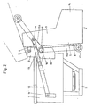
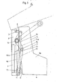
- a mixer 1 is mounted on a frame 2 and connected to a tractor (not shown).
- a support frame 3 for a blade 4, which is connected to a material feed chute 5, is also firmly connected to the mixer 1.
- the end of the material feed chute 5 remote from the blade 4 is attached to the support frame 3 so as to be pivotable about the pivot axis 7 via an extension 6.
- the material feed chute 5 is provided laterally along its bottom surface 8 with a boundary surface 9, and in the region of the blade 4 there are lateral boundary surfaces 9a.
- the boundary surfaces 9 and 9a are formed in one piece in the exemplary embodiment.
- a lifting device 10 is fastened to the support frame 3 of the mixer 1.
- the lifting device 10 comprises a lifting cylinder 12 with a piston rod 13 which is pivotably arranged at 11 on the support frame 3.
- a leg 15a of a rigid angle lever 15 with the leg 15a and the pair of legs 15b is pivotably attached at 14.
- the pair of legs 15b comprises two legs of equal length running parallel to one another at a distance from one another.
- the apex 16 of the angle lever 15 serves as a pivot axis, which is also arranged in a stationary manner on the support frame 3.
- the second pair of legs 15b protrudes lengthwise above the leg 15a and carries at its free end slide rollers 17 which rest on the bottom surface 8 of the material feed chute 5 and slide along the bottom surface 8 during the lifting movement of the blade 4.
- the lifting movement of the blade 4 takes place by retracting the piston rod 13, which is in the extended state during the loading position of the blade 4.
- the angle lever 15 rotates about its pivot axis 16
- the pair of legs 15b lifts and takes the blade 4 with it upwards, while the sliding rollers 17 slide along the bottom surface 8 of the material feed chute 5 until the Bucket 4 is in its unloading position above the mixer 1 and the loaded product slides along the feed chute 5 into the mixer 1 without damaging the surroundings and, above all, the lifting mechanism itself.
- the pivot point 7 of the pivotable blade 4 is higher than the upper edge of the mixer 1.
Landscapes
- Chemical & Material Sciences (AREA)
- Dispersion Chemistry (AREA)
- Accessories For Mixers (AREA)
Applications Claiming Priority (2)
| Application Number | Priority Date | Filing Date | Title |
|---|---|---|---|
| DE19868609175 DE8609175U1 (de) | 1986-04-05 | 1986-04-05 | Füllvorrichtung für eine Mischmaschine |
| DE8609175U | 1986-04-05 |
Publications (2)
| Publication Number | Publication Date |
|---|---|
| EP0240740A2 true EP0240740A2 (fr) | 1987-10-14 |
| EP0240740A3 EP0240740A3 (fr) | 1990-01-31 |
Family
ID=6793334
Family Applications (1)
| Application Number | Title | Priority Date | Filing Date |
|---|---|---|---|
| EP87103252A Withdrawn EP0240740A3 (fr) | 1986-04-05 | 1987-03-06 | Dispositif de chargement pour un mélangeur |
Country Status (2)
| Country | Link |
|---|---|
| EP (1) | EP0240740A3 (fr) |
| DE (1) | DE8609175U1 (fr) |
Cited By (1)
| Publication number | Priority date | Publication date | Assignee | Title |
|---|---|---|---|---|
| CN103112086A (zh) * | 2012-12-28 | 2013-05-22 | 中联重科股份有限公司 | 添加料系统及包括该系统的建筑材料制备设备 |
Family Cites Families (8)
| Publication number | Priority date | Publication date | Assignee | Title |
|---|---|---|---|---|
| FR391668A (fr) * | 1907-11-13 | 1908-11-06 | Malan De Mendoza Ver Mehr John | Dispositif élévateur pour introduire ou déverser des matières dans un récipient |
| US1467186A (en) * | 1922-03-20 | 1923-09-04 | Chain Belt Co | Safety guard |
| US1514032A (en) * | 1923-11-19 | 1924-11-04 | Foote Company | Loading skip for concrete pavers |
| US1775983A (en) * | 1928-06-16 | 1930-09-16 | Foote Company Inc | Concrete mixer |
| FR1069829A (fr) * | 1953-01-12 | 1954-07-13 | Dispositif pour le chargement des cuves de bétonnières | |
| FR70079E (fr) * | 1956-10-18 | 1959-02-02 | Ets Richier | Bétonnière à commande hydraulique |
| IE800392L (en) * | 1980-02-27 | 1981-08-27 | Donal Joseph O Donovan | Tractor-concrete mixer |
| GB2117260A (en) * | 1982-03-15 | 1983-10-12 | Sei Inc | Concrete mixing device |
-
1986
- 1986-04-05 DE DE19868609175 patent/DE8609175U1/de not_active Expired
-
1987
- 1987-03-06 EP EP87103252A patent/EP0240740A3/fr not_active Withdrawn
Cited By (2)
| Publication number | Priority date | Publication date | Assignee | Title |
|---|---|---|---|---|
| CN103112086A (zh) * | 2012-12-28 | 2013-05-22 | 中联重科股份有限公司 | 添加料系统及包括该系统的建筑材料制备设备 |
| CN103112086B (zh) * | 2012-12-28 | 2015-08-19 | 中联重科股份有限公司 | 添加料系统及包括该系统的建筑材料制备设备 |
Also Published As
| Publication number | Publication date |
|---|---|
| DE8609175U1 (de) | 1986-05-22 |
| EP0240740A3 (fr) | 1990-01-31 |
Similar Documents
| Publication | Publication Date | Title |
|---|---|---|
| DE2759058A1 (de) | Vorrichtung zum heben und senken von lasten | |
| DE2100680B2 (de) | Zusammenklappbare Fördervorrichtung an einem Transportmischer | |
| DE1456538A1 (de) | Vorrichtung zur auswechselbaren Halterung von Arbeitsgeraeten an Lademaschinen | |
| EP0240740A2 (fr) | Dispositif de chargement pour un mélangeur | |
| DE3302915C2 (fr) | ||
| DE1482095A1 (de) | Maehmaschine | |
| DE2743988C2 (de) | Ladegerät für den Einsatz in Tunnels o.dgl. | |
| DE1277778B (de) | Gewinnungs- oder Streckenvortriebsmaschine | |
| DE2915341B1 (de) | Rechenreiniger fuer Stabrechen | |
| DE3318338A1 (de) | Geraet zur entnahme von silage | |
| DE3412829A1 (de) | Foerdergut-ladegeraet | |
| DE3632718C2 (fr) | ||
| DE69102321T2 (de) | Vorrichtung zum Entnehmen von Silage und zum Beladen eines Wagens. | |
| DE2217765C2 (de) | Mit einer Ladevorrichtung versehene Abbaumascnine | |
| DE2115982A1 (de) | Bandfördergerät | |
| DE1856975U (de) | Muelltonnen-hubkipper an muellwagen. | |
| DE2620146A1 (de) | Fahrbares mehrzweck-kleinladegeraet | |
| DE1756429A1 (de) | Verfahren und Vorrichtung zum Entladen eines Transportwagens | |
| CH401832A (de) | Einrichtung zum Transport von Normlagergütern | |
| DE1078500B (de) | Dungfoerdervorrichtung | |
| AT346634B (de) | Stalldungstreuer | |
| DE1045301B (de) | Beschickungsvorrichtung zum Fuellen von Aufzugskuebeln von Betonmischern od. dgl. | |
| DE3411513A1 (de) | Ladewagen fuer blatt- und halmgut | |
| DE8214700U1 (de) | Geraet zur entnahme von silage | |
| DE1672378U (de) | Zughackenlader. |
Legal Events
| Date | Code | Title | Description |
|---|---|---|---|
| PUAI | Public reference made under article 153(3) epc to a published international application that has entered the european phase |
Free format text: ORIGINAL CODE: 0009012 |
|
| AK | Designated contracting states |
Kind code of ref document: A2 Designated state(s): AT DE FR GB |
|
| PUAL | Search report despatched |
Free format text: ORIGINAL CODE: 0009013 |
|
| AK | Designated contracting states |
Kind code of ref document: A3 Designated state(s): AT DE FR GB |
|
| STAA | Information on the status of an ep patent application or granted ep patent |
Free format text: STATUS: THE APPLICATION IS DEEMED TO BE WITHDRAWN |
|
| 18D | Application deemed to be withdrawn |
Effective date: 19900801 |