EP0240397B1 - Selbstbeblasender elektrischer Lastschalter mit rotierendem Lichtbogen - Google Patents
Selbstbeblasender elektrischer Lastschalter mit rotierendem Lichtbogen Download PDFInfo
- Publication number
- EP0240397B1 EP0240397B1 EP87400575A EP87400575A EP0240397B1 EP 0240397 B1 EP0240397 B1 EP 0240397B1 EP 87400575 A EP87400575 A EP 87400575A EP 87400575 A EP87400575 A EP 87400575A EP 0240397 B1 EP0240397 B1 EP 0240397B1
- Authority
- EP
- European Patent Office
- Prior art keywords
- electrode
- arc
- coil
- arcing contact
- circuit breaker
- Prior art date
- Legal status (The legal status is an assumption and is not a legal conclusion. Google has not performed a legal analysis and makes no representation as to the accuracy of the status listed.)
- Expired - Lifetime
Links
- 230000005291 magnetic effect Effects 0.000 claims description 18
- 230000008033 biological extinction Effects 0.000 claims description 7
- 238000004891 communication Methods 0.000 claims description 4
- SFZCNBIFKDRMGX-UHFFFAOYSA-N sulfur hexafluoride Chemical compound FS(F)(F)(F)(F)F SFZCNBIFKDRMGX-UHFFFAOYSA-N 0.000 claims description 3
- 229960000909 sulfur hexafluoride Drugs 0.000 claims description 3
- 239000003302 ferromagnetic material Substances 0.000 claims description 2
- 238000002955 isolation Methods 0.000 claims description 2
- 125000006850 spacer group Chemical group 0.000 claims description 2
- 239000007789 gas Substances 0.000 description 11
- 238000007664 blowing Methods 0.000 description 7
- 239000004020 conductor Substances 0.000 description 5
- 230000005284 excitation Effects 0.000 description 4
- 238000000926 separation method Methods 0.000 description 3
- 229910018503 SF6 Inorganic materials 0.000 description 2
- 238000001816 cooling Methods 0.000 description 2
- 230000000694 effects Effects 0.000 description 2
- 238000010891 electric arc Methods 0.000 description 2
- 239000011810 insulating material Substances 0.000 description 2
- 238000005192 partition Methods 0.000 description 2
- 230000010363 phase shift Effects 0.000 description 2
- RYGMFSIKBFXOCR-UHFFFAOYSA-N Copper Chemical compound [Cu] RYGMFSIKBFXOCR-UHFFFAOYSA-N 0.000 description 1
- 229910000881 Cu alloy Inorganic materials 0.000 description 1
- 238000004873 anchoring Methods 0.000 description 1
- 230000003416 augmentation Effects 0.000 description 1
- 230000001010 compromised effect Effects 0.000 description 1
- 229910052802 copper Inorganic materials 0.000 description 1
- 239000010949 copper Substances 0.000 description 1
- 238000002242 deionisation method Methods 0.000 description 1
- 238000010586 diagram Methods 0.000 description 1
- 238000010438 heat treatment Methods 0.000 description 1
- 239000000463 material Substances 0.000 description 1
- 239000002184 metal Substances 0.000 description 1
- 229910052751 metal Inorganic materials 0.000 description 1
- 230000005012 migration Effects 0.000 description 1
- 238000013508 migration Methods 0.000 description 1
- 230000037452 priming Effects 0.000 description 1
- 238000003466 welding Methods 0.000 description 1
Images

Classifications
-
- H—ELECTRICITY
- H01—ELECTRIC ELEMENTS
- H01H—ELECTRIC SWITCHES; RELAYS; SELECTORS; EMERGENCY PROTECTIVE DEVICES
- H01H33/00—High-tension or heavy-current switches with arc-extinguishing or arc-preventing means
- H01H33/70—Switches with separate means for directing, obtaining, or increasing flow of arc-extinguishing fluid
- H01H33/98—Switches with separate means for directing, obtaining, or increasing flow of arc-extinguishing fluid the flow of arc-extinguishing fluid being initiated by an auxiliary arc or a section of the arc, without any moving parts for producing or increasing the flow
- H01H33/982—Switches with separate means for directing, obtaining, or increasing flow of arc-extinguishing fluid the flow of arc-extinguishing fluid being initiated by an auxiliary arc or a section of the arc, without any moving parts for producing or increasing the flow in which the pressure-generating arc is rotated by a magnetic field
Definitions
- the arc capture electrode is attached to the front front face of the coil, and the tubular fixed or semi-fixed arc contact is set back from the electrode inside the coil.
- the switching of the arc on the electrode causes the supply coil to be energized after the contacts are separated.
- the centering effect of the arc by the action of the field is accentuated by the pneumatic blowing during the phase exhaust gas through the communication pipes between the breaking chamber and the expansion chamber. This results in a possibility of re-striking the arc root anchored on the electrode towards the fixed arcing contact, causing an almost total shunting of the coil.
- the decrease in the magnetic field in the arc zone causes the rotation of the arc roots to stop. The extinction of the arc is then compromised.
- the object of the invention is to improve the performance of a self-expanding and rotating arc circuit breaker.
- the circuit breaker according to the invention is characterized in that the fixed or semi-fixed arcing contact part is carried by the front front face of the coil and is electrically connected to it by one of its ends, that the electrode is on the one hand electrically isolated from the fixed arcing contact and from the said front face by an interval and is on the other hand connected to the opposite end of the coil by a bypass circuit arranged in the breaking chamber, at the outside of the coil, and that the front front face of the coil is capped by the electrode with interposition of said isolation gap, so as to allow the capture by said electrode of a fraction of the arc current making it possible to keep said magnetic field substantially constant, when the value of the intensity of the short-circuit current exceeds a predetermined threshold.
- the electrode has an annular edge for capturing the arc, allowing passage axial of the movable arc contact part towards the closed position, the fixed arc contact part being slightly set back relative to said edge of the electrode.
- the arc current When the arc current is not very large, the arc remains anchored between the fixed and movable arc contact parts, and moves in rotation under the action of the magnetic field created by the permanent excitation of the coil. The arc does not migrate on the electrode, causing the absence of current in the bypass circuit. If a predetermined threshold is exceeded, in the event of a major short-circuit, the current is automatically distributed in the coil and the bypass circuit.
- the excitation current of the coil is limited to a certain value allowing the maximum amplitude of the magnetic field in the arc zone to be adjusted. The excess current is shunted by the branch circuit.
- the annular rim of the electrode is advantageously equipped with a metallic extension of revolution, in particular cylindrical or curved, projecting from the fixed arc contact piece in the direction of the first support tube of the movable arc contact piece.
- the electrode can also play the role of a cooling element participating in the deionization of the arc in the breaking zone.
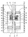
- a pole of an electric circuit breaker comprises an arc extinguishing device 10 with self-blowing by thermal expansion and with a rotating arc.
- the pole is housed in a sealed, cylindrical casing 12, filled with electronegative insulating gas with high dielectric strength, in particular sulfur hexafluoride SF 6, under an appropriate pressure.
- the casing 12 made of insulating material is internally subdivided into a first breaking chamber 14 containing the arc extinguishing device 10, and at least a second expansion chamber 16 allowing the escape of the breaking gases from the first chamber 14.
- the circuit breaker comprises a pair of separable arcing contacts 18, 20, hollow, arranged inside the first chamber 14 in alignment with the axial direction of the casing 12. The main contact system for the passage of the nominal current in the absence of a fault is not shown in the figures.
- the movable arcing contact 18 is carried by a first support tube 22 of conductive material passing axially sliding a cylindrical radial wall 24 of the breaking chamber 14.
- the tube 22 is mechanically secured to a control rod of a mechanism maneuver (not shown), and is provided with an axial duct 26 which communicates with the second expansion chamber 16 through orifices 28.
- the fixed arcing contact 20 is formed by a conductive annular track having an inside diameter equal to that of the movable arcing contact 18 to allow the contacts 18, 20 to abut, in the closed position.
- the track of the fixed arcing contact 20 constitutes a short-circuit ring fixed by welding to the front end face 30 of an electromagnetic coil 32 for rotating the electric arc drawn during the separation of the arcing contacts. 18, 20.
- the cylindrical coil 32 is fixed and is located in the first chamber 14, being carried by a second support tube 34 fixed in conductive material, which passes through a wall 36 of the chamber 14 opposite the other wall 24.
- An axial conduit 38 is formed in the second support tube 34, and communicates with the expansion chamber 16 through orifices 40.
- a cylindrical partition 42 surrounds the two walls 24, 36, radial to delimit the first breaking chamber 14 of the pole.
- the partition 42 may have any other suitable shape, for example spherical or ellipsoidal.
- the fixed arcing contact 20 is attached on the other hand to a hollow internal bushing 44, made of ferromagnetic material, surrounded coaxially by the coil 32 with the interposition of an insulating sheath 46.
- One end of the coil 32 is electrically connected to the tail of the track of the fixed arcing contact 20, and the opposite end is connected to a conductive sleeve 48 in connection with the second support tube 34.
- Bolts 49 for assembly ensure the mechanical fixing of the coil 32 to the sleeve 48.
- An annular electrode 50 is connected to the sleeve 48 by a bypass conductor 52 which externally surrounds the coil 32 inside the chamber 14.
- the electrode 50 is formed by a conductive ring extending radially along the front face 30 front of the coil 32, and separated from the latter by an axial gap 54 of thin thickness.
- the inside diameter of the annular electrode 50 is greater than the outside diameter of the sliding arcing contact 18 to allow the latter to end up with the fixed arcing contact 20 in the closed position.
- the fixed arcing contact 20 is in slight axial withdrawal relative to the free end of the electrode 50.
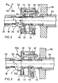
- FIG. 2 it can be seen that the rotation of the arc X in the cut-off zone 56 is due to the action of the radial component BR of the magnetic field B (see diagram in point M).
- the axial component Ba of the magnetic field B tends to maintain the arc X in the vicinity of the center to reinforce the anchoring of the arc roots on the fixed and movable arcing contacts 18.
- This centering effect of the arc X is accentuated by the centripetal gas blowing, during the self-expansion phase, generating a double reverse flow of the gases through the exhaust ducts 26, 38.
- the combined action of the magnetic field B and the gas blowing on the arc ensures permanent excitation of the coil 32.
- a fraction Y of the arc is picked up by the electrode 50, so as to cause a distribution of the arc current through the coil 32 and the external branch circuit 52.
- the excitation of the coil 32 is not interrupted during the cut-off phase and results from the fraction X of the arc current lying in parallel on fraction Y.
- the intensity of the magnetic field B in the breaking zone 56 is therefore limited to a predetermined threshold, independently of the value of the short-circuit current.
- the arc migration threshold on the electrode 50 of the bypass circuit 52 depends on the thickness of the axial gap 54, on the shape and on the spatial position of the electrode 50 in the breaking chamber 14, as well as the electrical resistivity of the conductive material constituting the bypass circuit 52.
- the additional fraction Y of the arc current is flowing in the bypass circuit 52 to shunt the coil 32.
- the partial arc Y also rotates under the action of field B and disappears as soon as the intensity of the arc current falls below a predetermined value.
- the presence of the annular metal electrode 50 in the breaking chamber 14 makes it possible to cool the arc roots to promote its extinction.
- the material of the electrode 50 is copper, or a copper alloy.
- the electrode 50 can also play the role of a phase shift ring between the magnetic field B, generated by the coil 32 and the arc current, so as to improve the blowing, in particular when the current crosses zero. It can thus be provided with a radial slot, if one does not want a phase shift between magnetic field and current.
- the priming electrode 50 can have different shapes as shown in FIG. 3, in particular an axial cylindrical socket 50a (lower half-view) extending the conductive radial ring of the branch circuit 52, or an extension 50 b curved in conductive material projecting from the fixed arcing contact 20 (upper half-view).
- the movable arcing contact 18 in translation can also cooperate with an arcing contact 20 semi-fixed subjected to the action of a return spring, or with a fixed arcing contact 20 in the form of a clamp.
- An intermediate ring 60 of insulating material, can be inserted in the axial gap 54 formed between the electrode 50 and the front end face 30 of the coil 32.
- a second annular electrode 62 can be associated with the electrode 50 of the branch circuit 52.
Landscapes
- Arc-Extinguishing Devices That Are Switches (AREA)
- Circuit Breakers (AREA)
Claims (9)
- Autoexpansions-Leistungsschalter mit Drehlichtbogen in dichtgekapseltem, mit einem Gas hoher dielektrischer Festigkeit, insbesondere Schwefelhexafluorid, gefüllten Gehäuse (12) und Lichtbogenlöschvorrichtung in einer Schaltkammer (14), die über Strömungskanäle mit einer angrenzenden Expansionskammer (16) verbunden ist, wobei die genannte Lichtbogenlöschvorrichtung (10) pro Pol aus folgenden Teilen besteht:- einem trennbaren Kontaktsystem (22, 18, 20, 48, 34) mit einem beweglichen Lichtbogenkontakt (18), der in der Schaltkammer (14) verschiebbar gelagert ist und mit einem festen oder halbfesten Kontakt (20) in der Einschaltstellung zusammenwirkt,- einer in der Schaltkammer (14) befindlichen Blasspule (32) zur Erzeugung eines Magnetfelds in der Unterbrechungszone (56) und einer daraus folgenden Lichtbogenrotation nach der Trennung der Lichtbogenkontakte (18, 20), wobei die Spule koaxial zum festen bzw. halbfesten Kontakt (20) angeordnet ist,- Strömungskanälen (26, 38) im Innern der hohl ausgeführten Lichtbogenkontakte (18, 20), durch die das in der Schaltkammer (14) verdichtete Gas in die Expansionskammer (16) entweichen kann,- einer Lichtbogen-Auffangelektrode (50, 50 a, 50 b) in der Unterbrechungszone (56), dadurch gekennzeichnet, daß der feste bzw. halbfeste Lichtbogenkontakt (20) an der Vorderseite (30) der Spule (32) angebracht und elektrisch mit einem Spulenende verbunden ist, daß die Auffangelektrode (50, 50 a, 50 b) einerseits gegenüber dem festen Lichtbogenkontakt durch einen Zwischenraum (54) isoliert und andererseits über einen in der Schaltkammer (14) außerhalb der Spule (32) angeordneten Parallelstromkreis mit dem zweiten Ende der Spule (32) verbunden ist, und daß die Auffangelektrode (50, 50 a, 50 b) die Vorderseite (30) der Spule (32) im Abstand des Zwischenraums (54) überlappt, derart, daß die genannte Elektrode einen Teil des Lichtbogenstroms auffängt und so das erzeugte Magnetfeld konstant gehalten werden kann, wenn der Kurzschlußstrom einen festgelegten Grenzwert überschreitet.
- Leistungsschalter nach Anspruch 1, dadurch gekennzeichnet, daß die Elektrode (50, 50 a, 50 b) einen ringförmigen Ansatz zum Auffangen des Lichtbogens aufweist, durch den der bewegliche Lichtbogenkontakt (18) in Richtung der Einschaltstellung hindurchgeführt werden kann, wobei der feste Lichtbogenkontakt (20) in bezug auf den genannten Ansatz der Elektrode (50) leicht nach hinten versetzt ist.
- Leistungsschalter nach Anspruch 2, dadurch gekennzeichnet, daß der ringförmige Ansatz der Auffangelektrode mit einem umlaufenden, insbesondere zylindrischen oder bogenförmigen, Kragen (50 a, 50 b) aus Metall versehen ist, der in Richtung des rohrförmigen Tragkörpers (22) für den beweglichen Lichtbogenkontakt (18) aus der festen Kontakteinheit (20) herausragt.
- Leistungsschalter nach einem der Ansprüche 1 bis 3, dadurch gekennzeichnet, daß der feste Lichtbogenkontakt (20) an der Vorderseite (30) der Spule (32) sowie auf einer den Tragkörper der Spule bildenden Hülse (44) aus ferromagnetischem Werkstoff befestigt ist und sich zwischen Spule und Hülse ein Isolierring (46) befindet.
- Leistungsschalter nach Anspruch 4, bei dem die Einheit aus Spule (32) und festem Lichtbogenkontakt (20) auf einem zweiten, mit einer der Anschlußklemmen des Pols verbundenen, rohrförmigen Tragkörper (34) befestigt ist, dadurch gekennzeichnet, daß der Parallelstromkreis (52) an der gegenüberliegenden Seite der Auffangelektrode (50) mit einer zwischen der Spulenrückseite und dem zweiten rohrförmigen Tragkörper (34) angeordneten leitenden Manschette (48) verbunden ist und letzterer in einer Achse mit dem ersten rohrförmigen Tragkörper (22) des beweglichen Lichtbogenkontakts (18) liegt.
- Leistungsschalter nach einem der Ansprüche 1 bis 5, dadurch gekennzeichnet, daß eine Isolierscheibe (60) in dem zwischen der Auffangelektrode (50) und der Spulenvorderseite (30) angeordneten axialen Zwischenraum (54) eingefügt wird.
- Leistungsschalter nach einem der Ansprüche 1 bis 6, dadurch gekennzeichnet, daß die Auffangelektrode (50, 50 a, 50 b) eine umlaufende Metalloberfläche zur Kühlung der Lichtbogenfußpunkte in der Unterbrechungszone (56) aufweist.
- Leistungsschalter nach einem der Ansprüche 1 oder 2, dadurch gekennzeichnet, daß die Auffangelektrode 50 einen radialen Spalt aufweist.
- Leistungsschalter nach einem der Ansprüche 1 oder 2, dadurch gekennzeichnet, daß der Parallelstromkreis 52 mit einer ringförmigen Hilfselektrode ausgerüstet ist, die in axialer Richtung durch einen Zwischenring 64 von der Hauptelektrode 50 getrennt ist, wobei der Innendurchmesser der Hilfselektrode 62 größer ist als der Innendurchmesser der Hauptelektrode 50.
Applications Claiming Priority (2)
| Application Number | Priority Date | Filing Date | Title |
|---|---|---|---|
| FR8604742 | 1986-03-28 | ||
| FR8604742A FR2596578B1 (fr) | 1986-03-28 | 1986-03-28 | Disjoncteur electrique a autoexpansion et a arc tournant |
Publications (2)
| Publication Number | Publication Date |
|---|---|
| EP0240397A1 EP0240397A1 (de) | 1987-10-07 |
| EP0240397B1 true EP0240397B1 (de) | 1992-06-03 |
Family
ID=9333834
Family Applications (1)
| Application Number | Title | Priority Date | Filing Date |
|---|---|---|---|
| EP87400575A Expired - Lifetime EP0240397B1 (de) | 1986-03-28 | 1987-03-16 | Selbstbeblasender elektrischer Lastschalter mit rotierendem Lichtbogen |
Country Status (8)
| Country | Link |
|---|---|
| US (1) | US4737607A (de) |
| EP (1) | EP0240397B1 (de) |
| JP (1) | JP2566946B2 (de) |
| CN (1) | CN1016123B (de) |
| DE (1) | DE3779474T2 (de) |
| ES (1) | ES2032840T3 (de) |
| FR (1) | FR2596578B1 (de) |
| YU (1) | YU47186B (de) |
Cited By (1)
| Publication number | Priority date | Publication date | Assignee | Title |
|---|---|---|---|---|
| DE10131018C1 (de) * | 2001-06-27 | 2003-01-23 | Siemens Ag | Leistungsschalter |
Families Citing this family (14)
| Publication number | Priority date | Publication date | Assignee | Title |
|---|---|---|---|---|
| FR2617633B1 (fr) * | 1987-07-02 | 1989-11-17 | Merlin Gerin | Disjoncteur a arc tournant et a expansion |
| FR2623657A1 (fr) * | 1987-11-19 | 1989-05-26 | Merlin Gerin | Disjoncteur a autosoufflage par expansion de gaz isolant, equipe d'un ecran de repartition de champ electrique |
| FR2677168B1 (fr) * | 1991-06-03 | 1994-06-17 | Merlin Gerin | Disjoncteur moyenne tension a energie de commande reduite. |
| FR2677487B1 (fr) * | 1991-06-10 | 1993-09-03 | Merlin Gerin | Interrupteur electrique sous vide. |
| DE19507583A1 (de) * | 1995-03-04 | 1996-09-05 | Abb Management Ag | Leistungsschalter |
| FR2732157B1 (fr) * | 1995-03-22 | 1997-05-09 | Schneider Electric Sa | Disjoncteur a gaz equipe d'une chambre a autoexpansion et a arc tournant |
| EP0850430A1 (de) | 1995-08-29 | 1998-07-01 | Orroyo Optics Inc. | Wellenlängenselektive optische gitter-koppler |
| US5875272A (en) * | 1995-10-27 | 1999-02-23 | Arroyo Optics, Inc. | Wavelength selective optical devices |
| KR100351300B1 (ko) * | 2000-09-27 | 2002-09-05 | 엘지산전 주식회사 | 회로차단기용 복합소호장치 |
| CN102543553A (zh) * | 2011-12-09 | 2012-07-04 | 沈阳工业大学 | Sf6断路器旋磁压气式灭弧室结构 |
| US9355798B2 (en) | 2014-08-21 | 2016-05-31 | General Electric Company | System and method for quenching an arc |
| FR3028089B1 (fr) * | 2014-10-30 | 2016-12-30 | Alstom Technology Ltd | Interrupteur ou disjoncteur a moyenne ou haute tension, pourvu de contacts fixes ameliores, et procede d'utilisation |
| CN109935480B (zh) * | 2019-04-29 | 2021-05-07 | 詹建英 | 一种断路器的触头灭弧装置 |
| CN113808891A (zh) * | 2021-10-18 | 2021-12-17 | 北京图力普联科技有限公司 | 自激气吹灭弧器 |
Family Cites Families (10)
| Publication number | Priority date | Publication date | Assignee | Title |
|---|---|---|---|---|
| GB1321812A (en) * | 1969-04-22 | 1973-07-04 | Reyrolle Co Ltd A | High-voltage gas circuit-breakers |
| JPS604535B2 (ja) * | 1973-08-03 | 1985-02-05 | 富士電機株式会社 | ロ−タリア−クしや断器 |
| US4153827A (en) * | 1976-01-26 | 1979-05-08 | Merlin Gerin | Magnetic blow-out arc extinguishing device |
| FR2418963A1 (fr) * | 1978-03-01 | 1979-09-28 | Merlin Gerin | Dispositif d'extinction d'arc a autosoufflage et a arc tournant |
| US4249052A (en) * | 1978-05-01 | 1981-02-03 | Electric Power Research Institute, Inc. | Arc spinner interrupter with chromium copper arcing contact |
| FR2441261A1 (fr) * | 1978-11-10 | 1980-06-06 | Merlin Gerin | Interrupteur a arc tournant |
| EP0021951A1 (de) * | 1979-06-14 | 1981-01-07 | Merlin Gerin | Selbstbeblasender Schalter mit Saugwirkung |
| JPS5923605B2 (ja) * | 1980-03-28 | 1984-06-04 | 日新電機株式会社 | ガスしや断器 |
| EP0042456B1 (de) * | 1980-06-23 | 1985-01-23 | BBC Aktiengesellschaft Brown, Boveri & Cie. | Hochspannungsleistungsschalter |
| YU173582A (en) * | 1981-09-16 | 1985-03-20 | Bbc Brown Boveri & Cie | Electrical switch |
-
1986
- 1986-03-28 FR FR8604742A patent/FR2596578B1/fr not_active Expired - Fee Related
-
1987
- 1987-03-16 ES ES198787400575T patent/ES2032840T3/es not_active Expired - Lifetime
- 1987-03-16 DE DE8787400575T patent/DE3779474T2/de not_active Expired - Fee Related
- 1987-03-16 EP EP87400575A patent/EP0240397B1/de not_active Expired - Lifetime
- 1987-03-18 US US07/027,322 patent/US4737607A/en not_active Expired - Lifetime
- 1987-03-25 CN CN87102961.8A patent/CN1016123B/zh not_active Expired
- 1987-03-26 YU YU53287A patent/YU47186B/sh unknown
- 1987-03-27 JP JP62073945A patent/JP2566946B2/ja not_active Expired - Lifetime
Cited By (1)
| Publication number | Priority date | Publication date | Assignee | Title |
|---|---|---|---|---|
| DE10131018C1 (de) * | 2001-06-27 | 2003-01-23 | Siemens Ag | Leistungsschalter |
Also Published As
| Publication number | Publication date |
|---|---|
| FR2596578A1 (fr) | 1987-10-02 |
| FR2596578B1 (fr) | 1994-05-06 |
| CN1016123B (zh) | 1992-04-01 |
| CN87102961A (zh) | 1987-10-07 |
| YU53287A (en) | 1989-08-31 |
| ES2032840T3 (es) | 1993-03-01 |
| DE3779474D1 (de) | 1992-07-09 |
| EP0240397A1 (de) | 1987-10-07 |
| DE3779474T2 (de) | 1993-03-25 |
| JPS62234823A (ja) | 1987-10-15 |
| US4737607A (en) | 1988-04-12 |
| YU47186B (sh) | 1995-01-31 |
| JP2566946B2 (ja) | 1996-12-25 |
Similar Documents
| Publication | Publication Date | Title |
|---|---|---|
| EP0240397B1 (de) | Selbstbeblasender elektrischer Lastschalter mit rotierendem Lichtbogen | |
| EP0298809B1 (de) | Selbstbeblasender elektrischer Lastschalter mit rotierendem Lichtbogen | |
| EP0385886B1 (de) | Lastschalter mit rotierendem Lichtbogen und mit Zentrifugal-Effekt des Löschgases | |
| EP0433184B1 (de) | Hybrid-Mittelspannungsschalter | |
| EP0388323B1 (de) | Elektrischer Autoexpansionsschalter mit Isoliergas | |
| FR2682807A1 (fr) | Disjoncteur electrique a deux cartouches a vide en serie. | |
| FR2491676A1 (fr) | Relais electromagnetique | |
| EP0709867B1 (de) | Elektrischer Vakuumschalter | |
| FR2841682A1 (fr) | Ampoule a vide pour un appareil de protection electrique tel un interrupteur ou un disjoncteur | |
| EP0053524B1 (de) | Elektrischer Schalter mit Selbstblasung durch Lichtbogenrotation | |
| FR2576144A1 (fr) | Disjoncteur a haute tension, a gaz comprime, a faible energie de manoeuvre | |
| EP0768692B1 (de) | Autoexpansionsschalter mit Isoliergas | |
| EP0759629B1 (de) | Lastschalter mit Einschaltwiderstand und Einfügungsvorrichtung | |
| EP0095406B1 (de) | Schalter mit rotierendem Lichtbogen und Permanentmagnet | |
| EP0004213B1 (de) | Lichtbogenlöscheinrichtung mit pneumatischer und magnetischer Blasung | |
| CA2017127C (fr) | Disjoncteur a moyenne tension a courant nominal eleve | |
| FR2743936A1 (fr) | Disjonteur a double mouvement des contacts | |
| EP0518786B1 (de) | Elektrischer Vakuumschalter | |
| CA2043025C (fr) | Disjoncteur a moyenne tension | |
| EP0823721B1 (de) | Selbstbeblasender elektrischer Lastschalter mit rotierendem Lichtbogen | |
| FR2623657A1 (fr) | Disjoncteur a autosoufflage par expansion de gaz isolant, equipe d'un ecran de repartition de champ electrique | |
| FR2683937A1 (fr) | Disjoncteur hybride pour la coupure des courants a grande composante continue. | |
| FR2464550A1 (fr) | Interrupteur a soufflage magnetique en rotation de l'arc | |
| EP0398116B1 (de) | Mittelspannungsschalter mit Selbstbeblasung | |
| FR2599187A1 (fr) | Disjoncteur electrique a isolement gazeux et a bobine de soufflage electromagnetique pour la rotation de l'arc |
Legal Events
| Date | Code | Title | Description |
|---|---|---|---|
| PUAI | Public reference made under article 153(3) epc to a published international application that has entered the european phase |
Free format text: ORIGINAL CODE: 0009012 |
|
| AK | Designated contracting states |
Kind code of ref document: A1 Designated state(s): BE CH DE ES GB IT LI SE |
|
| 17P | Request for examination filed |
Effective date: 19880314 |
|
| 17Q | First examination report despatched |
Effective date: 19901218 |
|
| GRAA | (expected) grant |
Free format text: ORIGINAL CODE: 0009210 |
|
| AK | Designated contracting states |
Kind code of ref document: B1 Designated state(s): BE CH DE ES GB IT LI SE |
|
| REF | Corresponds to: |
Ref document number: 3779474 Country of ref document: DE Date of ref document: 19920709 |
|
| ITF | It: translation for a ep patent filed | ||
| GBT | Gb: translation of ep patent filed (gb section 77(6)(a)/1977) | ||
| REG | Reference to a national code |
Ref country code: ES Ref legal event code: FG2A Ref document number: 2032840 Country of ref document: ES Kind code of ref document: T3 |
|
| PLBE | No opposition filed within time limit |
Free format text: ORIGINAL CODE: 0009261 |
|
| STAA | Information on the status of an ep patent application or granted ep patent |
Free format text: STATUS: NO OPPOSITION FILED WITHIN TIME LIMIT |
|
| 26N | No opposition filed | ||
| EAL | Se: european patent in force in sweden |
Ref document number: 87400575.4 |
|
| PGFP | Annual fee paid to national office [announced via postgrant information from national office to epo] |
Ref country code: CH Payment date: 19950315 Year of fee payment: 9 |
|
| PGFP | Annual fee paid to national office [announced via postgrant information from national office to epo] |
Ref country code: BE Payment date: 19950428 Year of fee payment: 9 |
|
| PGFP | Annual fee paid to national office [announced via postgrant information from national office to epo] |
Ref country code: ES Payment date: 19960328 Year of fee payment: 10 |
|
| PG25 | Lapsed in a contracting state [announced via postgrant information from national office to epo] |
Ref country code: LI Effective date: 19960331 Ref country code: CH Effective date: 19960331 Ref country code: BE Effective date: 19960331 |
|
| BERE | Be: lapsed |
Owner name: MERLIN GERIN Effective date: 19960331 |
|
| REG | Reference to a national code |
Ref country code: CH Ref legal event code: PL |
|
| PG25 | Lapsed in a contracting state [announced via postgrant information from national office to epo] |
Ref country code: ES Free format text: LAPSE BECAUSE OF NON-PAYMENT OF DUE FEES Effective date: 19970317 |
|
| REG | Reference to a national code |
Ref country code: ES Ref legal event code: FD2A Effective date: 19990503 |
|
| PGFP | Annual fee paid to national office [announced via postgrant information from national office to epo] |
Ref country code: SE Payment date: 20000307 Year of fee payment: 14 |
|
| PGFP | Annual fee paid to national office [announced via postgrant information from national office to epo] |
Ref country code: GB Payment date: 20000315 Year of fee payment: 14 |
|
| PGFP | Annual fee paid to national office [announced via postgrant information from national office to epo] |
Ref country code: DE Payment date: 20000318 Year of fee payment: 14 |
|
| PG25 | Lapsed in a contracting state [announced via postgrant information from national office to epo] |
Ref country code: GB Free format text: LAPSE BECAUSE OF NON-PAYMENT OF DUE FEES Effective date: 20010316 |
|
| PG25 | Lapsed in a contracting state [announced via postgrant information from national office to epo] |
Ref country code: SE Free format text: LAPSE BECAUSE OF NON-PAYMENT OF DUE FEES Effective date: 20010317 |
|
| EUG | Se: european patent has lapsed |
Ref document number: 87400575.4 |
|
| GBPC | Gb: european patent ceased through non-payment of renewal fee |
Effective date: 20010316 |
|
| PG25 | Lapsed in a contracting state [announced via postgrant information from national office to epo] |
Ref country code: DE Free format text: LAPSE BECAUSE OF NON-PAYMENT OF DUE FEES Effective date: 20020101 |
|
| PG25 | Lapsed in a contracting state [announced via postgrant information from national office to epo] |
Ref country code: IT Free format text: LAPSE BECAUSE OF NON-PAYMENT OF DUE FEES Effective date: 20050316 |