EP0240088A2 - A structure for use in magnetic induction recording and method of forming a magnetic storage device - Google Patents
A structure for use in magnetic induction recording and method of forming a magnetic storage device Download PDFInfo
- Publication number
- EP0240088A2 EP0240088A2 EP87200616A EP87200616A EP0240088A2 EP 0240088 A2 EP0240088 A2 EP 0240088A2 EP 87200616 A EP87200616 A EP 87200616A EP 87200616 A EP87200616 A EP 87200616A EP 0240088 A2 EP0240088 A2 EP 0240088A2
- Authority
- EP
- European Patent Office
- Prior art keywords
- further characterized
- layer
- protective layer
- zirconium
- intermediate layer
- Prior art date
- Legal status (The legal status is an assumption and is not a legal conclusion. Google has not performed a legal analysis and makes no representation as to the accuracy of the status listed.)
- Granted
Links
Images


Classifications
-
- G—PHYSICS
- G11—INFORMATION STORAGE
- G11B—INFORMATION STORAGE BASED ON RELATIVE MOVEMENT BETWEEN RECORD CARRIER AND TRANSDUCER
- G11B5/00—Recording by magnetisation or demagnetisation of a record carrier; Reproducing by magnetic means; Record carriers therefor
- G11B5/62—Record carriers characterised by the selection of the material
- G11B5/72—Protective coatings, e.g. anti-static or antifriction
- G11B5/722—Protective coatings, e.g. anti-static or antifriction containing an anticorrosive material
-
- Y—GENERAL TAGGING OF NEW TECHNOLOGICAL DEVELOPMENTS; GENERAL TAGGING OF CROSS-SECTIONAL TECHNOLOGIES SPANNING OVER SEVERAL SECTIONS OF THE IPC; TECHNICAL SUBJECTS COVERED BY FORMER USPC CROSS-REFERENCE ART COLLECTIONS [XRACs] AND DIGESTS
- Y10—TECHNICAL SUBJECTS COVERED BY FORMER USPC
- Y10S—TECHNICAL SUBJECTS COVERED BY FORMER USPC CROSS-REFERENCE ART COLLECTIONS [XRACs] AND DIGESTS
- Y10S428/00—Stock material or miscellaneous articles
- Y10S428/90—Magnetic feature
-
- Y—GENERAL TAGGING OF NEW TECHNOLOGICAL DEVELOPMENTS; GENERAL TAGGING OF CROSS-SECTIONAL TECHNOLOGIES SPANNING OVER SEVERAL SECTIONS OF THE IPC; TECHNICAL SUBJECTS COVERED BY FORMER USPC CROSS-REFERENCE ART COLLECTIONS [XRACs] AND DIGESTS
- Y10—TECHNICAL SUBJECTS COVERED BY FORMER USPC
- Y10T—TECHNICAL SUBJECTS COVERED BY FORMER US CLASSIFICATION
- Y10T428/00—Stock material or miscellaneous articles
- Y10T428/26—Web or sheet containing structurally defined element or component, the element or component having a specified physical dimension
- Y10T428/263—Coating layer not in excess of 5 mils thick or equivalent
- Y10T428/264—Up to 3 mils
- Y10T428/265—1 mil or less
Definitions
- This invention relates to thin film magnetic recording media and more specifically to magnetic media covered with material which prevents corrosion, improves wear resistance, and reduces the head to media dynamic and static friction coefficients.
- Metallic magnetic thin film disks used in memory applications typically comprise a substrate material which is coated with a magnetic alloy film which serves as the recording medium.
- the recording medium used in such disks is a cobalt-based alloy such as Co-Ni, Co-Cr, Co-Ni-Cr, Co-Pt or Co-Ni-Pt which is deposited by vacuum sputtering as discussed by J. K. Howard in "Thin Films For Magnetic Recording Technology: A Review", published in Journal of Vacuum Science & Technology, in January, 1986, incorporated herein by reference.
- Other prior art recording media comprises a Co-P or Co-Ni-P film deposited by chemical plating as discussed by Tu Chen et al.
- overcoating thin film magnetic recording media with a hard protective layer such as a carbon or Si0 2 layer improves the wear resistance of the recording media and also provides some corrosion protection to the magnetic film in a low humidity and low temperature environment.
- a hard protective layer such as a carbon or Si0 2 layer
- Carbon overcoatings for magnetic disks are described by F. K. King in “Datapoint Thin Film Media”, published in IEEE Transactions on Magnetics in July, 1981, and Japanese Patent Application 58140/77 filed May 18, 1977 by Hinata et al., incorporated herein by reference. It is possible, in principle, to increase the corrosion protection by increasing the thickness of the carbon or SiO 2 overcoat.
- the maximum thickness of the overcoat that is tolerable for high performance disk media is about 2 microinches (2u") to permit the read-write head to fly close to the media.
- the electrical performance of the disk is improved as the overcoat is made even thinner.
- the decrease in overcoat thickness decreases the "effective flying height" of the head on the media (i.e. the gap between the surface of the head and the magnetic layer), thereby improving the signal to noise ratio (S/N), resolution, and overwrite characteristics of the recording media.
- S/N signal to noise ratio
- the overcoat does not provide sutticient corrosion protection for the magnetic media.
- the chromium layer provides enhanced corrosion resistance while the carbon overcoat provides good wear resistance.
- the total overcoat thickness must be greater than 2 ⁇ ", which is not desirable for a high performance disk.
- the overcoat must not only protect the magnetic film from corrosion, but it must also protect the magnetic film from wear.
- a further requirement is that the static and dynamic friction coefficients between the read-write head and the overcoat must remain low over a large number of start/stop cycles.
- the static friction coefficient is the ratio of lateral force to the normal loading force on the head as the disk starts to rotate.
- the dynamic friction coefficient is the ratio of the lateral force to the normal loading force after the disk has started to rotate.
- the static friction coefficient between the head and the overcoat material are too high (greater than 1.0)
- a small motor used in the drive will have difficulty starting rotation of the disk from a stationary position, and if a large motor drives the disk, the motor may cause the head to break off from the head suspension.
- the static and dynamic friction coefficients are too high, mechanical contact between the read-write head and the disk will cause excessive wear in the overcoat and eventually a head crash.
- the head When the disk is rotating in the drive, the head "flies" at a typical distance of about Su” to 15p" above the disk. When the drive is turned off, the head comes into physical contact with the disk. Since the drive is likely to be repeatedly turned on and off during its lifetime, the overcoat must protect the magnetic film from wear, and at the same time, the static and dynamic friction coefficients between the head and the overcoat must remain low after repeated start/stop cycles. It has been demonstrated that even though hard carbon and Si0 2 overcoats resist wear well, their static and dynamic friction coefficients increase dramatically after repeated start/stop cycles.
- a protective Layer of a zi r - conium oxide compound, such as ZrO 2 is formed on a film of magnetic recording media thereby enhancing resistance to corrosion and providing good wear resistance and a reduced static and dynamic friction coefficients.
- the magnetic recording media can be any suitable media, such as a Co-Pt, Co-Ni-Cr, Co-Ni-Pt, Co-Cr, Co-Ni, Co-Cr-Pt-, or other cobalt-based alloy deposited by sputtering or plating, or Co-P or Co-Ni-P deposited by a chemical plating process.
- the magnetic recording media can also be an iron-based alloy. We have found that a thin layer of the zirconium compound greatly inhibits corrosion in such films and provides good wear resistance and a low static friction coefficient even after repeated start/stop cycles.
- the layer is zirconium oxide, zirconium boride, zirconium carbide and zirconium nitride and is formed by sputterinq.
- the sputtering target used to provide the ZrO Z Layer comprises a solid solution including Zro 2 and a stabilizer such as Y 2 O 3 , CaO, Mg0 or any of a number of other stabilizers.
- an intermediate layer of material is provided between the Zr0 2 layer and the magnetic media.
- the intermediate layer adheres strongly to both the 2rO 2 layer and the media.
- the disk wear resistance is enhanced.
- the tendency of the static and dynamic friction coefficients to increase after repeated start/stop cycles is reduced by the presence of the intermediate layer. The reason for this is that without the intermediate layer, the stress applied to the bond between the Zr0 2 and media by the friction force of the read-write head against the disk may cause the Zro 2 layer to peel and blister after prolonged repeated start/stop cycles if the bonding between the Zro 2 and magnetic media is not sufficiently strong.
- the peeling can cause asperities on the media surface which further increase static and dynamic friction between the head and disk, and therefore increase wear.
- the peeling also causes entrapment of debris (comprised mainly of the overcoat material) between the head and media surface, which further increases static and dynamic friction. This can eventually cause a head crash or a catastrophic failure.
- the intermediate layer which exhibits strong adhesion to both the Zr0 2 layer and the media, peeling and blistering can be substantially avoided, and the tendency of the static and dynamic friction coefficients to increase as a function of the number of start/stop cycles can be reduced.
- the intermediate layer typically comprises chromium, zirconium, hafnium, titanium, tantalum, tungsten or an alloy thereof.
- an intermediate layer as described above can also be used in conjunction with overcoats other than Zr0 2 .
- an intermediate layer as described above is provided between the disk media and a hard protective layer comprising the boride, nitride, or carbide of hafnium, zirconium, tantalum or titanium.
- the hard protective layer comprises the oxide of tantalum, titanium, or hafnium.
- the identity of the intermediate layer depends in part on the identity of the material selected for the protective overcoat.
- a hard disk constructed in accordance with one embodiment of our invention is fabricated by plating an NiP layer onto an aluminum substrate.
- a film of magnetic recording media is then formed on the NiP layer.
- the film can be Co-Ni-Pt, Co-Ni, Co-Pt, Co-Ni-Cr, Co-Cr, Co-Cr-Pt, or any other appropriate cobalt-based alloy deposited by any appropriate process such as vacuum evaporation, sputtering, electroplating, or electroless plating.
- Co-p, Co-Ni-P, iron-based or other alloys can also be used.
- the recording media is typically about 70 nm thick or less.
- a Zr0 2 layer is then sputtered onto the recording media, typically to a thickness between 10 and 60 nm.
- the Zr0 2 is typically formed by RF diode or RF magnetron sputtering. During RF sputtering, the gas pressure in the sputtering apparatus is typically 3 to 30 millitorr of argon.
- the Zr0 2 film can also be formed by electron beam evaporation, chemical vapor deposition, or plasma assisted chemical vapor deposition.
- the Zr0 2 layer inhibits corrosion in the magnetic recording media. This is illustrated in Table 1 below which compares corrosion in Zr0 2 coated films with corrosion in films coated with carbon instead of Zr0 2 .
- the data of Table 1 was taken by placing four disks in an environment of 90 to 95% relative humidity and 80°C for seven days.
- the first disk in Table I included a Co-Ni-Pt media covered with 2501 thick carbon
- the second disk included a chromium layer covered with Co-Ni media covered with 2501 thick carbon
- the third disk included Co-Ni-Pt media covered with 2001 thick Zr0 2
- the fourth disk included Co-Ni-Pt covered with 200 ⁇ thick chromium covered with 200 ⁇ thick Zr0 2 . Corrosion was evaluated by visual tests, magnetic tests and glide height tests.
- Corrosion on disks can be visibly detected since Co- based films corrode to form cobalt oxide or cobalt hydroxide, and thus appear blue compared to the original gold or brown color.
- the magnetic test includes testing for an increase in the number of defect sites on the surface of the disk after exposure to the above-described environment.
- An increase in the number of defect sites occurs because the magnetic media corrodes and becomes nonmagnetic, hence the recording head is not able to record data at the site of corrosion.
- a typical uncorroded disk contains less than 10 defects per surface. If the defect count in one of the disks of Table 1 increased by 20 defects from an initial defect count, it was considered to have failed.
- the films covered with Zr0 2 showed no sign of corrosion after five days in the above-described environment, while the films which were not covered by ZrO 2 became unusable due to corrosion.
- both the Zr0 2 covered films passed the visual, magnetic and glide height tests although one of the films exhibited a slight increase in the number of defect sites on the seventh day (possibly due to some corrosion on areas without the Zr0 2 overcoat e.g., because of dust particles resting on the media surfase prior to Zr0 2 deposition).
- ZrO 2 and ZrO 2 -chromium overcoated disks show extremely high corrosion resistance even though the thickness of the Zr0 2 overcoat is Less than 1 ⁇ "(250 ⁇ ) and the thickness of the Zr0 2 -chromium overcoat is Less than 2 ⁇ "(500 ⁇ ).
- Zr0 2 overcoat alone or ZrO 2 -chromium overcoat is a superior corrosion barrier for high performance disks compared to a carbon overcoat.
- the chromium Layer also causes the Zr0 2 Layer to adhere more strongly to the underlying media and enhances disk reLiabiLity.
- the sputtering target includes a stabilizer such as Y 2 O 3 , LaO, CaO, ThO 2 , CeO 2 , MgO, HfO 2 , Sc 2 O 3 , or other rare earth oxide.
- a number of other stabilizers are also appropriate.
- the stablizer prevents phase transformation of the Zr0 2 to the monoclinic phase, thus making the Zr0 2 sputtering target and the resulting film less brittle.
- a typical sputtering target used in accordance with our invention is 1 to 20% stabilizer by weight (preferably 4 to 15%) and the remainder Zr0 2 .
- the film composition depends on the sputtering target composition.
- the ZrO 2 sputtering target contains no stabilizer.
- a film including more than 20% stabilizer is used.
- the sputtering target includes A1 2 0 3 as well as a stablizer to further enhance the hardness of the sputtered protective overcoat.
- A1 2 0 3 and the stablizer prevent the sputtering target from fracturing.
- the target includes about 12% Y 2 O 3 , 5 to 20% A1 2 0 3 , and the remainder Zr0 2 . Films having this composition are particularly suitable for disks used with thin film read-write heads made of titanium carbide.
- other strength enhancing oxides such as Ce0 2 or Ti0 2 can also be included in the sputtering target and hence protective overcoat.
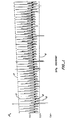
- Figure 1 illustrates the results of a static friction test for a magnetic disk including an overcoat of 88% ZrO 2 and 12% Y 2 0 3 stabilizer formed directly on Co-Ni-Pt magnetic media by RF sputtering while Figures 2a and 2b illustrate corresponding results for two magnetic disks coated with diamond-like carbon instead of the Zr0 2 and the stablizer.
- the disks of Figures 2a and 2b have slightly different surface textures on the microscopic level.
- each read-write head was pushed against the corresponding disk with a force of 15 grams applied in a direction perpendicular to the disk surface.
- the read-write head was positioned at an approximately fixed distance from the center of the disk before the disk started to rotate. As the disk started to rotate, the lateral force exerted on the head by the static friction force was measured by a transducer attached to the suspension of the head.
- a signal from the transducer was then recorded on the strip chart shown in Figures 1, 2a, and 2b.
- the static friction coefficient is approximately proportional to the distance from the center of the waveforms of Figures 1, 2a, and 2b to the envelope 8 surrounding the waveforms.
- each start/stop cycle caused one upwardly extending spike such as spike 10 and two downwardly extending spikes such as spikes 12.
- the static friction coefficient us equals the static friction force exerted on the read-write head and dividing it by the normal head loading force, which in this case is 15 grams.
- the static friction force exerted on the read-write head by the carbon coated film increased over time much more rapidly than the static friction force exerted on the read- write head by the Zr0 2 coated film.
- Figure 3 illustrates the change in static friction coefficient versus the number of start/stop cycles for four disks including a conventional diamond-like carbon coating formed directly on a Co-Ni-Pt film (curves 1 to 4), and for two disks each with a coating including 88% Zr0 2 and 12t Y 2 0 3 formed directly on a Co-Ni-Pt film (curves 5 and 6).
- the data illustrated in Figures 3 to 5 was taken by performing start/stop tests in the same manner as to the tests described above in relation to Figures 1, 2a and 2b.
- the surface roughness textures of the disks of curves 1 to 4 were different, thus causing the static friction characteristics of these disks to differ.
- the surface of the NiP layer on the aluminum substrate of the disk of curve 1 was smoother than the surfaces of the disks of curves 2 to 4 and, therefore, the disk of curve 1 exhibited greater static friction than the disks of curves 2 to 4.
- the static friction coefficient for a first disk coated with Zr0 2 started at 0.32 and increased to 0.39 after 100 cycles (curve 5).
- a second disk coated with ZrO 2 initially exhibited a static friction coefficient of 0.39 which increased to 0.40 after 20 cycles (curve 6).
- the carbon-coated disk corresponding to curve 1 initially exhibited a static friction coefficient of about 0.49 which increased to a value greater than 1.4 after only 5 starts.
- the other films coated with carbon initially exhibited static friction coefficients of 0.30, 0.35, and 0.40, respectively, which increased to 0.90, 0.60 and 0.80, after 45, 10, and 20 cycles, respectively (curves 2, 3, and 4). Accordingly, it is seen that films coated with Zr0 2 exhibited static friction coefficients which remained at lower values over time than carbon-coated Co-Ni-Pt films.
- the wear resistance of Zr0 2 overcoated disks is superior to carbon overcoated disks.
- a Zr0 2 overcoated disk without additional lubrication can last more than 10,000 fast start/stop cycles while a diamond like carbon overcoated disk without additional lubrication tends to wear out in less than 5,000 fast start/stop cycles.
- the disk In a fast start/stop cycle test, the disk is repeatedly rotated from a stationary position to a rotational velocity of about 3600 rpm so that the disk head flies above the media surface. This is in contrast to the start/stop cycles discussed in relation to Figures 1, 2a and 2b, in which the disk is rotated to a maximum velocity of 300 rpm and the read-write head never flies.
- a fast start/stop cycle test which closely simulates actual use, causes less wear than a 300 rpm start/stop cycle test.
- Application of lubrication increases the wear resistance of both Zr0 2 and carbon coated disks such that they continue to function properly after more than 50,000 fast start/stop cycles.
- Typical lubricants used to enhance the wear resistance of magnetic disks are discussed in the above- incorporated Suganuma paper.
- start/stop cycles e.g. more than 10,000 fast cycles
- the static friction coefficient of a disk coated with zro 2 and a lubricant generally remains lower than the static friction coefficient of a disk coated with carbon and a lubricant.
- the control of reliability of such a disk can be enhanced by sputtering an intermediate layer of material onto the recording media prior to forming the Zr0 2 layer.
- the intermediate layer typically comprises chromium, zirconium, hafnium, titanium, tantalum, tungsten, or any alloy thereof.
- these materials alloy easily with magnetic recording media such as Co-Ni-Pt and therefore strongly adhere to the media.
- each of these materials forms a strong bond to Zr0 2 .
- the intermediate layer is between 10 and 100AP and preferably between 30 and 40A.
- the intermediate material is thin to minimize the total thickness of the layers above the magnetic media, but thick enough to adequately cover the media.
- the intermediate layer comprises chromium
- the intermediate layer enhances control of the reliability of the magnetic disk. Even though a Zr0 2 protective film formed directly on magnetic media provides excellent protection against wear, we have discovered that after repeated start/stop cycles (e.g. greater than 100 cycles in a 300 rpm start/stop cycle test), the Zr0 2 film formed directly on magnetic media may blister and peel because of stress introduced at the bond between the Zr0 2 and the media by the friction force exerted by the read-write head on the Zr0 2 . This results in entrapment of debris (comprised mainly of the overcoat material) between the head and media surface. This further increases the static and dynamic friction coefficients and the rate of wear finally causes a head crash or a catastrophic failure in the media. By providing the intermediate layer, the peeling and blistering problems are avoided, the above- mentioned increase in static and dynamic friction is reduced, and catastrophic media failure or a head crash is prevented.
- start/stop cycles e.g. greater than 100 cycles in a 300 rpm start/stop cycle test
- Figure 4 illustrates the gradual increase in static and dynamic friction as a result of repeated 300 rpm start/stop cycles between a read-write head and an 88% Zr0 2 12% Y 2 0 3 layer formed by RF magnetron sputtering directly on Co-Ni-Pt recording media.
- the distance from the center of the waveform in Figure 4 to the waveform envelope is proportional to the static friction coefficient.
- the distance from the waveform center to the lower envelope of dark region 14 of the waveform is proportional to the dynamic friction coefficient. (Dark region 14 represents read/write head displacement caused by dynamic friction.)
- the static and dynamic friction coefficients are initially 0.2 and 0.12, respectively, but increase to 0.6 and 0.4, respectively, after about 231 start/stop cycles.
- Figure 5 illustrates the static and dynamic friction coefficients as a result of repeated 300 rpm start/stop cycles between a read-write head and an 88% Zr0 2 12% Y 2 0 3 layer formed under the same sputtering conditions as the ZrO 2 /Y 2 O 3 film of Figure 4 but with the addition of a chromium layer formed between the ZrO 2 , and the Co-Ni-Pt recording media.
- the static and dynamic friction coefficients are initially 0.22 and 0.21, respectively, but increase to only 0.4 and 0.3, respectively, after 1008 start/stop cycles.
- the intermediate layer further enhances the superior qualities of a ZrO 2 protective overcoat on a magnetic disk.
- the intermediate layer can be used to enhance protective overcoats other than ZrO 2 overcoats.
- the oxide of hafnium, tantalum, or titanium is used as a hard protective overcoat on a magnetic disk
- chromium, zirconium, hafnium, tantalum, titanium, tungsten, or an alloy thereof can be used as the intermediate layer.
- the hard protective layer is about 200 ⁇ thick and the intermediate layer is about 10 to 100 ⁇ thick.
- the intermediate layer typically comprises the base metal used to form the protective overcoat.
- the overcoat is zirconium carbide
- the intermediate layer is typically zirconium or a zirconium alloy.
- the protective layer is hafnium nitride
- the intermediate layer is hafnium or a hafnium alloy.
- an intermediate layer is formed between the media and the bottom layer of the plurality of layers to enhance adhesion between the plurality of layers and the media.
- an intermediate layer in accordance with our invention can be formed in a magnetic disk using other multilayer structures.
- an intermediate layer typically a noble metal or an alloy of a noble metal such as platinum, rhodium, palladium
- a noble metal typically a noble metal or an alloy of a noble metal such as platinum, rhodium, palladium
- a noble metal such as platinum, rhodium, or palladium is formed between the chromium and carbon layers to enhance the bonding between the carbon and the rest of the disk.
- a Zr0 2 layer is applied to a floppy disk.
- a Zro 2 layer in accordance with our invention can also be formed on magnetic tape or a recording drum as well. Accordingly, all such changes come within the invention.
Landscapes
- Magnetic Record Carriers (AREA)
- Manufacturing Of Magnetic Record Carriers (AREA)
Abstract
Description
- This invention relates to thin film magnetic recording media and more specifically to magnetic media covered with material which prevents corrosion, improves wear resistance, and reduces the head to media dynamic and static friction coefficients.
- Metallic magnetic thin film disks used in memory applications typically comprise a substrate material which is coated with a magnetic alloy film which serves as the recording medium. Typically, the recording medium used in such disks is a cobalt-based alloy such as Co-Ni, Co-Cr, Co-Ni-Cr, Co-Pt or Co-Ni-Pt which is deposited by vacuum sputtering as discussed by J. K. Howard in "Thin Films For Magnetic Recording Technology: A Review", published in Journal of Vacuum Science & Technology, in January, 1986, incorporated herein by reference. Other prior art recording media comprises a Co-P or Co-Ni-P film deposited by chemical plating as discussed by Tu Chen et al. in "Microstructure and Magnetic Properties of Electroless Co-P Thin Films Grown on an Aluminum Base Disk Substrate", published in the Journal of Applied Physics in March, 1978, and Y. Suganuma et al. in "Production Process and High Density Recording Characteristics of Plated Disks", published in IEEE Transactions on Magnetics in November, 1982, also incorporated herein by reference. Several problems are encountered in using unprotected metallic thin film recording media. For example, unprotected metallic thin films tend to corrode, particularly under high humidity conditions. Further, such films have very little resistance to wear caused by frequent contact with the recording head.
- To prevent these problems, it is known in the art of recording technology that overcoating thin film magnetic recording media with a hard protective layer such as a carbon or Si02 layer improves the wear resistance of the recording media and also provides some corrosion protection to the magnetic film in a low humidity and low temperature environment. Carbon overcoatings for magnetic disks are described by F. K. King in "Datapoint Thin Film Media", published in IEEE Transactions on Magnetics in July, 1981, and Japanese Patent Application 58140/77 filed May 18, 1977 by Hinata et al., incorporated herein by reference. It is possible, in principle, to increase the corrosion protection by increasing the thickness of the carbon or SiO2 overcoat. However, the maximum thickness of the overcoat that is tolerable for high performance disk media is about 2 microinches (2u") to permit the read-write head to fly close to the media. Of importance, the electrical performance of the disk is improved as the overcoat is made even thinner. The decrease in overcoat thickness decreases the "effective flying height" of the head on the media (i.e. the gap between the surface of the head and the magnetic layer), thereby improving the signal to noise ratio (S/N), resolution, and overwrite characteristics of the recording media. Unfortunately, if the carbon or Si02 overcoat thickness is less than 2u", the overcoat does not provide sutticient corrosion protection for the magnetic media.
- To improve the corrosion protection of the magnetic media provided by carbon, it is known in the art to deposit a thin chromium layer between the magnetic thin film media and the overcoat layer. In this multilayer overcoat structure, the chromium layer provides enhanced corrosion resistance while the carbon overcoat provides good wear resistance. However, in order to have effective corrosion resistance as well as good wear resistance provided by the carbon-chromium multilayer structure, the total overcoat thickness must be greater than 2µ", which is not desirable for a high performance disk.
- As mentioned earlier, the overcoat must not only protect the magnetic film from corrosion, but it must also protect the magnetic film from wear. A further requirement is that the static and dynamic friction coefficients between the read-write head and the overcoat must remain low over a large number of start/stop cycles. (The static friction coefficient is the ratio of lateral force to the normal loading force on the head as the disk starts to rotate. The dynamic friction coefficient is the ratio of the lateral force to the normal loading force after the disk has started to rotate.) If the static friction coefficient between the head and the overcoat material are too high (greater than 1.0), a small motor used in the drive will have difficulty starting rotation of the disk from a stationary position, and if a large motor drives the disk, the motor may cause the head to break off from the head suspension. In addition, if the static and dynamic friction coefficients are too high, mechanical contact between the read-write head and the disk will cause excessive wear in the overcoat and eventually a head crash.
- When the disk is rotating in the drive, the head "flies" at a typical distance of about Su" to 15p" above the disk. When the drive is turned off, the head comes into physical contact with the disk. Since the drive is likely to be repeatedly turned on and off during its lifetime, the overcoat must protect the magnetic film from wear, and at the same time, the static and dynamic friction coefficients between the head and the overcoat must remain low after repeated start/stop cycles. It has been demonstrated that even though hard carbon and Si02 overcoats resist wear well, their static and dynamic friction coefficients increase dramatically after repeated start/stop cycles.
- Because of the above-described mechanical and corrosion problems, it would be desirable to coat a magnetic disk with an overcoat material which would improve corrosion protection of the magnetic film without being excessively thick and at the same time exhibit good wear resistance and consistently low static and dynamic friction coefficients.
- In accordance with our invention, a protective Layer of a zir- conium oxide compound, such as ZrO2 is formed on a film of magnetic recording media thereby enhancing resistance to corrosion and providing good wear resistance and a reduced static and dynamic friction coefficients. The magnetic recording media can be any suitable media, such as a Co-Pt, Co-Ni-Cr, Co-Ni-Pt, Co-Cr, Co-Ni, Co-Cr-Pt-, or other cobalt-based alloy deposited by sputtering or plating, or Co-P or Co-Ni-P deposited by a chemical plating process. In addition, the magnetic recording media can also be an iron-based alloy. We have found that a thin layer of the zirconium compound greatly inhibits corrosion in such films and provides good wear resistance and a low static friction coefficient even after repeated start/stop cycles.
- Preferably, the layer is zirconium oxide, zirconium boride, zirconium carbide and zirconium nitride and is formed by sputterinq. In the further description it is referred to ZrO2. In one embodiment, the sputtering target used to provide the ZrOZ Layer comprises a solid solution including Zro2 and a stabilizer such as Y2O3, CaO, Mg0 or any of a number of other stabilizers.
- In one embodiment, an intermediate layer of material is provided between the Zr02 layer and the magnetic media. Of importance, the intermediate layer adheres strongly to both the 2rO2 layer and the media. We have discovered that by providing the intermediate layer, the disk wear resistance is enhanced. In addition, the tendency of the static and dynamic friction coefficients to increase after repeated start/stop cycles is reduced by the presence of the intermediate layer. The reason for this is that without the intermediate layer, the stress applied to the bond between the Zr02 and media by the friction force of the read-write head against the disk may cause the Zro2 layer to peel and blister after prolonged repeated start/stop cycles if the bonding between the Zro2 and magnetic media is not sufficiently strong. The peeling can cause asperities on the media surface which further increase static and dynamic friction between the head and disk, and therefore increase wear. The peeling also causes entrapment of debris (comprised mainly of the overcoat material) between the head and media surface, which further increases static and dynamic friction. This can eventually cause a head crash or a catastrophic failure. By providing the intermediate layer, which exhibits strong adhesion to both the Zr02 layer and the media, peeling and blistering can be substantially avoided, and the tendency of the static and dynamic friction coefficients to increase as a function of the number of start/stop cycles can be reduced. In an embodiment including a Zro2 overcoat, the intermediate layer typically comprises chromium, zirconium, hafnium, titanium, tantalum, tungsten or an alloy thereof.
- It is noted that an intermediate layer as described above can also be used in conjunction with overcoats other than Zr02. For example, in one embodiment, an intermediate layer as described above is provided between the disk media and a hard protective layer comprising the boride, nitride, or carbide of hafnium, zirconium, tantalum or titanium. In another embodiment, the hard protective layer comprises the oxide of tantalum, titanium, or hafnium. As described below, the identity of the intermediate layer depends in part on the identity of the material selected for the protective overcoat.
-
- Figure 1 illustrates the results of a static and dynamic friction test performed on a disk coated with Zr02 in which the disk was repeatedly rotationally displaced to a maximum rotation of 300 rpm from a stationary position (i.e. a start/stop cycle test);
- Figures 2a and 2b illustrate the results of a static and dynamic friction test performed on a pair of conventional carbon coated disks in which the disks were repeatedly rotationally displaced from a stationary position:
- Figure 3 illustrates the variation in the static friction coefficient as function of the number of start/stop cycles for a number of disks having various overcoats;
- Figure 4 illustrates the increase, as a result of repeated start/stop cycles, in dynamic and static friction coefficients between a read-write head and a disk in which Zr02 is formed directly on the media; and
- Figure 5 illustrates the increase in dynamic and static friction coefficients between a read-write head and a disk coated with a chromium layer which in turn is coated with Zr02.
- A hard disk constructed in accordance with one embodiment of our invention is fabricated by plating an NiP layer onto an aluminum substrate. A film of magnetic recording media is then formed on the NiP layer. The film can be Co-Ni-Pt, Co-Ni, Co-Pt, Co-Ni-Cr, Co-Cr, Co-Cr-Pt, or any other appropriate cobalt-based alloy deposited by any appropriate process such as vacuum evaporation, sputtering, electroplating, or electroless plating. In addition, Co-p, Co-Ni-P, iron-based or other alloys can also be used. The recording media is typically about 70 nm thick or less.
- A Zr02 layer is then sputtered onto the recording media, typically to a thickness between 10 and 60 nm. The Zr02 is typically formed by RF diode or RF magnetron sputtering. During RF sputtering, the gas pressure in the sputtering apparatus is typically 3 to 30 millitorr of argon. The Zr02 film can also be formed by electron beam evaporation, chemical vapor deposition, or plasma assisted chemical vapor deposition. Advantageously, the Zr02 layer inhibits corrosion in the magnetic recording media. This is illustrated in Table 1 below which compares corrosion in Zr02 coated films with corrosion in films coated with carbon instead of Zr02. The data of Table 1 was taken by placing four disks in an environment of 90 to 95% relative humidity and 80°C for seven days. The first disk in Table I included a Co-Ni-Pt media covered with 2501 thick carbon, the second disk included a chromium layer covered with Co-Ni media covered with 2501 thick carbon, the third disk included Co-Ni-Pt media covered with 2001 thick Zr02, and the fourth disk included Co-Ni-Pt covered with 200Å thick chromium covered with 200Å thick Zr02. Corrosion was evaluated by visual tests, magnetic tests and glide height tests.
- Corrosion on disks can be visibly detected since Co- based films corrode to form cobalt oxide or cobalt hydroxide, and thus appear blue compared to the original gold or brown color.
- The magnetic test includes testing for an increase in the number of defect sites on the surface of the disk after exposure to the above-described environment. An increase in the number of defect sites occurs because the magnetic media corrodes and becomes nonmagnetic, hence the recording head is not able to record data at the site of corrosion. A typical uncorroded disk contains less than 10 defects per surface. If the defect count in one of the disks of Table 1 increased by 20 defects from an initial defect count, it was considered to have failed.
- A film failed the glide height test if a read-write head suspended 5 µ" above the disk surface struck a mound of residual material from corrosion while the disk rotated. As can be seen, the films covered with Zr02 showed no sign of corrosion after five days in the above-described environment, while the films which were not covered by ZrO2 became unusable due to corrosion. After seven days, both the Zr02 covered films passed the visual, magnetic and glide height tests although one of the films exhibited a slight increase in the number of defect sites on the seventh day (possibly due to some corrosion on areas without the Zr02 overcoat e.g., because of dust particles resting on the media surfase prior to Zr02 deposition).
- As shown in Table 1, ZrO2 and ZrO2-chromium overcoated disks show extremely high corrosion resistance even though the thickness of the Zr02 overcoat is Less than 1µ "(250 Å) and the thickness of the Zr02-chromium overcoat is Less than 2µ"(500 Å). These results show that the Zr02 overcoat alone or ZrO2-chromium overcoat is a superior corrosion barrier for high performance disks compared to a carbon overcoat. (As described in greater detail below, the chromium Layer also causes the Zr02 Layer to adhere more strongly to the underlying media and enhances disk reLiabiLity.)

- When the ZrO2 is sputtered onto the magnetic recording media, in one embodiment, the sputtering target includes a stabilizer such as Y2O3, LaO, CaO, ThO2, CeO2, MgO, HfO2, Sc2O3, or other rare earth oxide. In addition, a number of other stabilizers are also appropriate. (The stablizer prevents phase transformation of the Zr02 to the monoclinic phase, thus making the Zr02 sputtering target and the resulting film less brittle.) A typical sputtering target used in accordance with our invention is 1 to 20% stabilizer by weight (preferably 4 to 15%) and the remainder Zr02. (If the stablizer concentration in the film is too high, its strength is degraded. The film composition depends on the sputtering target composition.) However, in another embodiment of our invention, the ZrO2 sputtering target contains no stabilizer.In yet another embodiment, a film including more than 20% stabilizer is used.
- in yet other embodiments of our invention, the sputtering target includes A1203 as well as a stablizer to further enhance the hardness of the sputtered protective overcoat. Of importance, both A1203 and the stablizer prevent the sputtering target from fracturing. In one embodiment, the target includes about 12% Y2O3, 5 to 20% A1203, and the remainder Zr02. Films having this composition are particularly suitable for disks used with thin film read-write heads made of titanium carbide. In addition, other strength enhancing oxides such as Ce02 or Ti02 can also be included in the sputtering target and hence protective overcoat.
- We have discovered that aside from being corrosion resistant, the Zr02 layer also exhibits superior mechanical qualities. Figure 1 illustrates the results of a static friction test for a magnetic disk including an overcoat of 88% ZrO2 and 12% Y203 stabilizer formed directly on Co-Ni-Pt magnetic media by RF sputtering while Figures 2a and 2b illustrate corresponding results for two magnetic disks coated with diamond-like carbon instead of the Zr02 and the stablizer. The disks of Figures 2a and 2b have slightly different surface textures on the microscopic level. The data in these figures was taken by repetitively starting to rotate the disks from a stationary position to a maximum rotational velocity of 300 rpm and then stopping the disks and measuring the lateral force exerted on the read-write head caused by static friction between the read-write head and the carbon coated and Zr02 coated disks. During these tests, each read-write head was pushed against the corresponding disk with a force of 15 grams applied in a direction perpendicular to the disk surface. The read-write head was positioned at an approximately fixed distance from the center of the disk before the disk started to rotate. As the disk started to rotate, the lateral force exerted on the head by the static friction force was measured by a transducer attached to the suspension of the head. A signal from the transducer was then recorded on the strip chart shown in Figures 1, 2a, and 2b. The static friction coefficient is approximately proportional to the distance from the center of the waveforms of Figures 1, 2a, and 2b to the
envelope 8 surrounding the waveforms. In the strip charts of Figures 1, 2a, and 2b, each start/stop cycle caused one upwardly extending spike such as spike 10 and two downwardly extending spikes such as spikes 12. The static friction coefficient us equals the static friction force exerted on the read-write head and dividing it by the normal head loading force, which in this case is 15 grams. As can be seen, the static friction force exerted on the read-write head by the carbon coated film increased over time much more rapidly than the static friction force exerted on the read- write head by the Zr02 coated film. - Referring to Figure 1, a static friction coefficient of less than 0.3 was consistently measured when performing about 45 start/stop cycle tests on the Zr02 coated disk In contrast, in Figure 2a, an initial static friction coefficient of about 0.4 was measured during the first pass of the static friction test on the carbon-coated disk, which then rapidly increased to about 0.8 by the eighth pass. In Figure 2b, an initial static friction coefficient of 0.2 was measured, increasing to about 0.8 by the eleventh pass. (The read-write head in Figures 1, 2a and 2b was displaced in both positive and negative directions. This is because of oscillatory motion of the read-write head during the start/stop tests.)
- Figure 3 illustrates the change in static friction coefficient versus the number of start/stop cycles for four disks including a conventional diamond-like carbon coating formed directly on a Co-Ni-Pt film (curves 1 to 4), and for two disks each with a coating including 88% Zr02 and 12t Y203 formed directly on a Co-Ni-Pt film (curves 5 and 6). (The data illustrated in Figures 3 to 5 was taken by performing start/stop tests in the same manner as to the tests described above in relation to Figures 1, 2a and 2b.) The surface roughness textures of the disks of curves 1 to 4 were different, thus causing the static friction characteristics of these disks to differ. Specifically, the surface of the NiP layer on the aluminum substrate of the disk of curve 1 (and therefore the surface of the carbon coating of the disk of curve 1) was smoother than the surfaces of the disks of curves 2 to 4 and, therefore, the disk of curve 1 exhibited greater static friction than the disks of curves 2 to 4. In addition, the surface roughness texture of the disks of
curves 5 and 6, although differing slightly, had a roughness texture similar to the surface roughness textures of the disks of curves 2 to 4. - As can be seen, the static friction coefficient for a first disk coated with Zr02 started at 0.32 and increased to 0.39 after 100 cycles (curve 5). A second disk coated with ZrO2 initially exhibited a static friction coefficient of 0.39 which increased to 0.40 after 20 cycles (curve 6). In contrast, the carbon-coated disk corresponding to curve 1 initially exhibited a static friction coefficient of about 0.49 which increased to a value greater than 1.4 after only 5 starts. The other films coated with carbon initially exhibited static friction coefficients of 0.30, 0.35, and 0.40, respectively, which increased to 0.90, 0.60 and 0.80, after 45, 10, and 20 cycles, respectively (curves 2, 3, and 4). Accordingly, it is seen that films coated with Zr02 exhibited static friction coefficients which remained at lower values over time than carbon-coated Co-Ni-Pt films.
- The wear resistance of Zr02 overcoated disks is superior to carbon overcoated disks. We have discovered that a Zr02 overcoated disk without additional lubrication can last more than 10,000 fast start/stop cycles while a diamond like carbon overcoated disk without additional lubrication tends to wear out in less than 5,000 fast start/stop cycles. (In a fast start/stop cycle test, the disk is repeatedly rotated from a stationary position to a rotational velocity of about 3600 rpm so that the disk head flies above the media surface. This is in contrast to the start/stop cycles discussed in relation to Figures 1, 2a and 2b, in which the disk is rotated to a maximum velocity of 300 rpm and the read-write head never flies. A fast start/stop cycle test, which closely simulates actual use, causes less wear than a 300 rpm start/stop cycle test.) Application of lubrication increases the wear resistance of both Zr02 and carbon coated disks such that they continue to function properly after more than 50,000 fast start/stop cycles. (Typical lubricants used to enhance the wear resistance of magnetic disks are discussed in the above- incorporated Suganuma paper.) However, after a large number of start/stop cycles (e.g. more than 10,000 fast cycles), the static friction coefficient of a disk coated with zro2 and a lubricant generally remains lower than the static friction coefficient of a disk coated with carbon and a lubricant.
- As mentioned above, although a disk including magnetic media covered with Zr02 exhibits superior mechanical qualities, the control of reliability of such a disk can be enhanced by sputtering an intermediate layer of material onto the recording media prior to forming the Zr02 layer. The intermediate layer typically comprises chromium, zirconium, hafnium, titanium, tantalum, tungsten, or any alloy thereof. Advantageously, these materials alloy easily with magnetic recording media such as Co-Ni-Pt and therefore strongly adhere to the media. In addition, each of these materials forms a strong bond to Zr02. In one embodiment, the intermediate layer is between 10 and 100AP and preferably between 30 and 40A. The intermediate material is thin to minimize the total thickness of the layers above the magnetic media, but thick enough to adequately cover the media.
- When the intermediate layer comprises chromium, it is typically desirable to use a high voltage biased sputtering target. This ensures that the sputtered chromium particles have a high velocity when they strike the recording media, and thus the resulting chromium layer adheres strongly to the underlying media.
- As mentioned above, the intermediate layer enhances control of the reliability of the magnetic disk. Even though a Zr02 protective film formed directly on magnetic media provides excellent protection against wear, we have discovered that after repeated start/stop cycles (e.g. greater than 100 cycles in a 300 rpm start/stop cycle test), the Zr02 film formed directly on magnetic media may blister and peel because of stress introduced at the bond between the Zr02 and the media by the friction force exerted by the read-write head on the Zr02. This results in entrapment of debris (comprised mainly of the overcoat material) between the head and media surface. This further increases the static and dynamic friction coefficients and the rate of wear finally causes a head crash or a catastrophic failure in the media. By providing the intermediate layer, the peeling and blistering problems are avoided, the above- mentioned increase in static and dynamic friction is reduced, and catastrophic media failure or a head crash is prevented.
- Figure 4 illustrates the gradual increase in static and dynamic friction as a result of repeated 300 rpm start/stop cycles between a read-write head and an 88
% Zr0 2 12% Y203 layer formed by RF magnetron sputtering directly on Co-Ni-Pt recording media. As was the case in Figures 1, 2a, and 2b, the distance from the center of the waveform in Figure 4 to the waveform envelope is proportional to the static friction coefficient. The distance from the waveform center to the lower envelope ofdark region 14 of the waveform is proportional to the dynamic friction coefficient. (Dark region 14 represents read/write head displacement caused by dynamic friction.) As can be seen, the static and dynamic friction coefficients are initially 0.2 and 0.12, respectively, but increase to 0.6 and 0.4, respectively, after about 231 start/stop cycles. - Figure 5 illustrates the static and dynamic friction coefficients as a result of repeated 300 rpm start/stop cycles between a read-write head and an 88
% Zr0 2 12% Y203 layer formed under the same sputtering conditions as the ZrO2/Y2O3 film of Figure 4 but with the addition of a chromium layer formed between the ZrO2, and the Co-Ni-Pt recording media. As can be seen, the static and dynamic friction coefficients are initially 0.22 and 0.21, respectively, but increase to only 0.4 and 0.3, respectively, after 1008 start/stop cycles. Thus, it is seen that the intermediate layer further enhances the superior qualities of a ZrO2 protective overcoat on a magnetic disk. - It is noted that the intermediate layer can be used to enhance protective overcoats other than ZrO2 overcoats. For example, when the oxide of hafnium, tantalum, or titanium is used as a hard protective overcoat on a magnetic disk, chromium, zirconium, hafnium, tantalum, titanium, tungsten, or an alloy thereof can be used as the intermediate layer. In such an embodiment, the hard protective layer is about 200Å thick and the intermediate layer is about 10 to 100Å thick.
- If the carbide, nitride or boride of zirconium, tantalum, titanium, or hafnium is used to form a protective layer, the intermediate layer typically comprises the base metal used to form the protective overcoat. For example, if the overcoat is zirconium carbide, the intermediate layer is typically zirconium or a zirconium alloy. If the protective layer is hafnium nitride, the intermediate layer is hafnium or a hafnium alloy.
- In yet another embodiment of the invention, if a plurality of layers are formed on magnetic recording media, an intermediate layer is formed between the media and the bottom layer of the plurality of layers to enhance adhesion between the plurality of layers and the media.
- While the invention has been described with respect to a specific embodiment, those skilled in the art will recognize that changes can be made in form and detail without departing from the spirit and scope of the invention. For example, an intermediate layer in accordance with our invention can be formed in a magnetic disk using other multilayer structures. Thus, in a disk including a hard layer of carbon as the protective overcoat, an intermediate layer (typically a noble metal or an alloy of a noble metal such as platinum, rhodium, palladium) can be provided between the carbon and media. In a disk comprising magnetic media covered with chromium (to minimize corrosion) which in turn is covered with carbon (to protect against wear), a noble metal such as platinum, rhodium, or palladium is formed between the chromium and carbon layers to enhance the bonding between the carbon and the rest of the disk.
- In addition, instead of using an NiP plated aluminum substrate, other substrates can be used, e.g. glass or ceramic substrates. Also, in some embodiments of our invention, a Zr02 layer is applied to a floppy disk. A Zro2 layer in accordance with our invention can also be formed on magnetic tape or a recording drum as well. Accordingly, all such changes come within the invention.
Claims (38)
Applications Claiming Priority (4)
| Application Number | Priority Date | Filing Date | Title |
|---|---|---|---|
| US06/847,990 US4929500A (en) | 1986-04-03 | 1986-04-03 | Corrosion resistant magnetic disk |
| US943333 | 1986-12-17 | ||
| US06/943,333 US4898774A (en) | 1986-04-03 | 1986-12-17 | Corrosion and wear resistant magnetic disk |
| US847990 | 1997-04-21 |
Publications (3)
| Publication Number | Publication Date |
|---|---|
| EP0240088A2 true EP0240088A2 (en) | 1987-10-07 |
| EP0240088A3 EP0240088A3 (en) | 1990-02-07 |
| EP0240088B1 EP0240088B1 (en) | 1993-10-27 |
Family
ID=27126737
Family Applications (1)
| Application Number | Title | Priority Date | Filing Date |
|---|---|---|---|
| EP87200616A Expired - Lifetime EP0240088B1 (en) | 1986-04-03 | 1987-04-02 | A structure for use in magnetic induction recording and method of forming a magnetic storage device |
Country Status (4)
| Country | Link |
|---|---|
| US (1) | US4898774A (en) |
| EP (1) | EP0240088B1 (en) |
| JP (1) | JP2571224B2 (en) |
| DE (1) | DE3787911T2 (en) |
Cited By (13)
| Publication number | Priority date | Publication date | Assignee | Title |
|---|---|---|---|---|
| EP0350412A1 (en) * | 1988-07-05 | 1990-01-10 | Thomson-Csf | Device made of magnetic material with anti-wear layer and application to a recording/reproducing head and a recording disk |
| EP0279581A3 (en) * | 1987-02-18 | 1990-03-07 | AT&T Corp. | Magneto-optic memory |
| US5078846A (en) * | 1990-08-14 | 1992-01-07 | Seagate Technology, Inc. | Process for forming hafnia and zirconia based protective films on longitudinal magnetic recording media |
| WO2014062222A1 (en) * | 2012-10-18 | 2014-04-24 | Seagate Technology Llc | Articles including intermediate layer and methods of forming |
| US8830800B1 (en) | 2013-06-21 | 2014-09-09 | Seagate Technology Llc | Magnetic devices including film structures |
| KR20140145123A (en) * | 2012-02-03 | 2014-12-22 | 시게이트 테크놀로지 엘엘씨 | Methods of forming layers |
| US9218829B2 (en) | 2013-06-24 | 2015-12-22 | Seagate Technology Llc | Devices including at least one intermixing layer |
| US9280989B2 (en) | 2013-06-21 | 2016-03-08 | Seagate Technology Llc | Magnetic devices including near field transducer |
| US9305572B2 (en) | 2014-05-01 | 2016-04-05 | Seagate Technology Llc | Methods of forming portions of near field transducers (NFTS) and articles formed thereby |
| US9672848B2 (en) | 2015-05-28 | 2017-06-06 | Seagate Technology Llc | Multipiece near field transducers (NFTS) |
| US9824709B2 (en) | 2015-05-28 | 2017-11-21 | Seagate Technology Llc | Near field transducers (NFTS) including barrier layer and methods of forming |
| US9852748B1 (en) | 2015-12-08 | 2017-12-26 | Seagate Technology Llc | Devices including a NFT having at least one amorphous alloy layer |
| US10192573B2 (en) | 2015-03-22 | 2019-01-29 | Seagate Technology Llc | Devices including metal layer |
Families Citing this family (27)
| Publication number | Priority date | Publication date | Assignee | Title |
|---|---|---|---|---|
| US5209835A (en) * | 1988-03-03 | 1993-05-11 | Asahi Glass Company Ltd. | Method for producing a specified zirconium-silicon amorphous oxide film composition by sputtering |
| JPH01258222A (en) * | 1988-04-08 | 1989-10-16 | Mitsubishi Electric Corp | magnetic disk |
| JP2659016B2 (en) * | 1988-05-21 | 1997-09-30 | 富士通株式会社 | Magnetic recording media |
| US5236791A (en) * | 1988-08-31 | 1993-08-17 | Hitachi, Ltd. | Magnetic recording medium and magnetic storage |
| JPH0283802A (en) * | 1988-09-20 | 1990-03-23 | Mitsubishi Electric Corp | magnetic disk device |
| JPH0762890B2 (en) * | 1988-10-04 | 1995-07-05 | 富士写真フイルム株式会社 | Thin film magnetic head |
| US5074983A (en) * | 1989-04-21 | 1991-12-24 | Hmt Technology Corporation | Thin film testing method |
| JP2763165B2 (en) * | 1989-07-10 | 1998-06-11 | 株式会社東芝 | Manufacturing method of magnetic recording medium |
| JPH0369011A (en) * | 1989-08-07 | 1991-03-25 | Tokin Corp | Perpendicular magnetic recording medium and production thereof |
| US5066552A (en) * | 1989-08-16 | 1991-11-19 | International Business Machines Corporation | Low noise thin film metal alloy magnetic recording disk |
| US5949612A (en) * | 1995-03-21 | 1999-09-07 | Censtor Corp. | Low friction sliding hard disk drive system |
| US5119258A (en) * | 1990-02-06 | 1992-06-02 | Hmt Technology Corporation | Magnetic disc with low-friction glass substrate |
| TW279972B (en) * | 1993-06-21 | 1996-07-01 | Komag Inc | |
| US5453168A (en) * | 1993-08-25 | 1995-09-26 | Tulip Memory Systems, Inc. | Method for forming protective overcoatings for metallic-film magnetic-recording mediums |
| US5631094A (en) * | 1994-01-28 | 1997-05-20 | Komag, Incorporated | Magnetic alloy for improved corrosion resistance and magnetic performance |
| US5554428A (en) * | 1994-09-01 | 1996-09-10 | Aluminum Company Of America | Memory disk sheet stock and method |
| US5871621A (en) | 1994-09-27 | 1999-02-16 | Komag, Incorporated | Method of fabricating a textured magnetic storage disk |
| IT1276536B1 (en) * | 1995-04-18 | 1997-11-03 | Siv Soc Italiana Vetro | PROCEDURE TO IMPROVE THE ABRASION RESISTANCE AND CHEMICAL INERTIA PROPERTIES OF THIN TRANSPARENT COATINGS. |
| US5506017A (en) * | 1995-06-07 | 1996-04-09 | Komag Incorporated | Method for texturing magnetic media |
| US5747135A (en) * | 1995-12-08 | 1998-05-05 | Aluminum Company Of America | Thin film pretreatment for memory disks and associated methods |
| US6139950A (en) * | 1998-06-04 | 2000-10-31 | Seagate Technology Llc | Magnetic recording medium containing a Cr(HfO2) or Cr(ZrO2) |
| US6430114B1 (en) | 2000-05-12 | 2002-08-06 | Toda Citron Technologies, Inc. | Self-lubricating layer for a data storage disk |
| US6677105B2 (en) | 2000-05-12 | 2004-01-13 | Toda Kogyo Corporation | Self-lubricating layer for data storage devices |
| US6512382B1 (en) * | 2001-07-17 | 2003-01-28 | International Business Machines Corporation | Method for corrosion susceptibility testing of magnetic heads using simulated disk corrosion products |
| WO2004008450A1 (en) * | 2002-06-05 | 2004-01-22 | Seagate Technology Llc | Protective overcoatings |
| US8767350B2 (en) | 2010-12-06 | 2014-07-01 | HGST Netherlands B.V. | Magnetic recording medium having recording regions and separating regions and methods of manufacturing the same |
| US9045348B2 (en) | 2012-08-29 | 2015-06-02 | HGST Netherlands B.V. | Titanium-silicon protective film composition and apparatus |
Family Cites Families (23)
| Publication number | Priority date | Publication date | Assignee | Title |
|---|---|---|---|---|
| US3912461A (en) * | 1970-11-02 | 1975-10-14 | Texas Instruments Inc | Low temperature metal carbonitride coatings |
| US4277540A (en) * | 1971-05-03 | 1981-07-07 | Aine Harry E | Thin film magnetic recording medium |
| US4124736A (en) * | 1974-10-29 | 1978-11-07 | Poly-Disc Systems, Inc. | Surface protected magnetic recording members |
| US4411963A (en) * | 1976-10-29 | 1983-10-25 | Aine Harry E | Thin film recording and method of making |
| DE2756254C3 (en) * | 1976-12-17 | 1981-12-24 | Nippon Electric Co., Ltd., Tokyo | Magnetic recording element |
| US4152487A (en) * | 1976-12-17 | 1979-05-01 | Nippon Electric Co., Ltd. | Magnetic record member |
| JPS585566B2 (en) * | 1978-06-27 | 1983-01-31 | 住友電気工業株式会社 | Cable lifting device in a tunnel |
| JPS5619517A (en) * | 1979-07-25 | 1981-02-24 | Matsushita Electric Ind Co Ltd | Magnetic head |
| US4503125A (en) * | 1979-10-01 | 1985-03-05 | Xebec, Inc. | Protective overcoating for magnetic recording discs and method for forming the same |
| DE3117931C2 (en) * | 1980-05-06 | 1985-07-25 | Nippon Electric Co., Ltd., Tokio/Tokyo | Magnetic recording medium and process for its manufacture |
| JPS57176537A (en) * | 1981-04-21 | 1982-10-29 | Canon Inc | Magnetic recording medium |
| JPS5819739A (en) * | 1981-07-29 | 1983-02-04 | Sony Corp | Thin film magnetic recording medium |
| US4649448A (en) * | 1983-06-03 | 1987-03-10 | Hitachi, Ltd. | Thin film magnetic head having a sliding surface |
| JPS6057533A (en) * | 1983-09-08 | 1985-04-03 | Hitachi Maxell Ltd | Magnetic recording medium |
| JPS6093618A (en) * | 1983-10-27 | 1985-05-25 | Teruo Fujii | Plate magnetic recording body and detection of signal inputting condition |
| JPS60258727A (en) * | 1984-06-06 | 1985-12-20 | Denki Kagaku Kogyo Kk | Magnetic storage medium |
| JPS6129437A (en) * | 1984-07-20 | 1986-02-10 | Canon Inc | Photomagnetic recording medium |
| JPS6174103A (en) * | 1984-09-20 | 1986-04-16 | Hitachi Metals Ltd | Magnetic recorder |
| JPH065574B2 (en) * | 1984-11-12 | 1994-01-19 | 株式会社東芝 | Magnetic recording medium |
| JPS61131224A (en) * | 1984-11-30 | 1986-06-18 | Toshiba Corp | Magnetic recording medium |
| JPH0673204B2 (en) * | 1984-12-28 | 1994-09-14 | 株式会社リコー | Thermosensitive magnetic recording material |
| DE3610041C2 (en) * | 1985-03-22 | 1996-09-05 | Noritake Co Ltd | Zirconia based ceramic with alumina, spinel, mullite or spinel and mullite and with improved hydrothermal and thermal stability |
| JPS62175949A (en) * | 1985-10-15 | 1987-08-01 | Nippon Kogaku Kk <Nikon> | Photomagnetic recording medium protected by compound oxide |
-
1986
- 1986-12-17 US US06/943,333 patent/US4898774A/en not_active Expired - Fee Related
-
1987
- 1987-04-02 JP JP62079819A patent/JP2571224B2/en not_active Expired - Lifetime
- 1987-04-02 DE DE87200616T patent/DE3787911T2/en not_active Expired - Fee Related
- 1987-04-02 EP EP87200616A patent/EP0240088B1/en not_active Expired - Lifetime
Cited By (27)
| Publication number | Priority date | Publication date | Assignee | Title |
|---|---|---|---|---|
| EP0279581A3 (en) * | 1987-02-18 | 1990-03-07 | AT&T Corp. | Magneto-optic memory |
| FR2634051A1 (en) * | 1988-07-05 | 1990-01-12 | Thomson Csf | MAGNETIC MATERIAL DEVICE WITH ANTI-WEAR LAYER AND APPLICATIONS TO A RECORDING-PLAYING HEAD AND RECORDING DISK |
| WO1990000793A1 (en) * | 1988-07-05 | 1990-01-25 | Thomson-Csf | Device made of magnetic material with anti-wear layer and applications to a recording-reading head and to a recording disc |
| EP0350412A1 (en) * | 1988-07-05 | 1990-01-10 | Thomson-Csf | Device made of magnetic material with anti-wear layer and application to a recording/reproducing head and a recording disk |
| US5078846A (en) * | 1990-08-14 | 1992-01-07 | Seagate Technology, Inc. | Process for forming hafnia and zirconia based protective films on longitudinal magnetic recording media |
| EP0474333A1 (en) * | 1990-08-14 | 1992-03-11 | Seagate Technology International | A process for manufacturing a magnetic recording medium |
| US9275833B2 (en) | 2012-02-03 | 2016-03-01 | Seagate Technology Llc | Methods of forming layers |
| KR20140145123A (en) * | 2012-02-03 | 2014-12-22 | 시게이트 테크놀로지 엘엘씨 | Methods of forming layers |
| WO2014062222A1 (en) * | 2012-10-18 | 2014-04-24 | Seagate Technology Llc | Articles including intermediate layer and methods of forming |
| KR101771185B1 (en) * | 2012-10-18 | 2017-08-24 | 시게이트 테크놀로지 엘엘씨 | Articles including intermediate layer and methods of forming |
| US9280989B2 (en) | 2013-06-21 | 2016-03-08 | Seagate Technology Llc | Magnetic devices including near field transducer |
| US8830800B1 (en) | 2013-06-21 | 2014-09-09 | Seagate Technology Llc | Magnetic devices including film structures |
| US9099146B2 (en) | 2013-06-21 | 2015-08-04 | Seagate Technology Llc | Magnetic devices including film structures |
| US9343099B2 (en) | 2013-06-21 | 2016-05-17 | Seagate Technology Llc | Magnetic devices including film structures |
| US9218829B2 (en) | 2013-06-24 | 2015-12-22 | Seagate Technology Llc | Devices including at least one intermixing layer |
| US9502054B2 (en) | 2013-06-24 | 2016-11-22 | Seagate Technology Llc | Devices including at least one intermixing layer |
| US9842613B2 (en) | 2014-05-01 | 2017-12-12 | Seagate Technology Llc | Methods of forming portions of near field transducers (NFTS) and articles formed thereby |
| US9305572B2 (en) | 2014-05-01 | 2016-04-05 | Seagate Technology Llc | Methods of forming portions of near field transducers (NFTS) and articles formed thereby |
| US10424324B2 (en) | 2014-05-01 | 2019-09-24 | Seagate Technology Llc | Methods of forming portions of near field transducers (NFTS) and articles formed thereby |
| US10192573B2 (en) | 2015-03-22 | 2019-01-29 | Seagate Technology Llc | Devices including metal layer |
| US10636440B2 (en) | 2015-03-22 | 2020-04-28 | Seagate Technology Llc | Devices including metal layer |
| US9672848B2 (en) | 2015-05-28 | 2017-06-06 | Seagate Technology Llc | Multipiece near field transducers (NFTS) |
| US9824709B2 (en) | 2015-05-28 | 2017-11-21 | Seagate Technology Llc | Near field transducers (NFTS) including barrier layer and methods of forming |
| US10229704B2 (en) | 2015-05-28 | 2019-03-12 | Seagate Technology Llc | Multipiece near field transducers (NFTS) |
| US10311906B2 (en) | 2015-05-28 | 2019-06-04 | Seagate Technology Llc | Near field transducers (NFTS) including barrier layer and methods of forming |
| US9852748B1 (en) | 2015-12-08 | 2017-12-26 | Seagate Technology Llc | Devices including a NFT having at least one amorphous alloy layer |
| US10068592B1 (en) | 2015-12-08 | 2018-09-04 | Seagate Technology Llc | Devices including a NFT having at least one amorphous alloy layer |
Also Published As
| Publication number | Publication date |
|---|---|
| EP0240088A3 (en) | 1990-02-07 |
| DE3787911D1 (en) | 1993-12-02 |
| DE3787911T2 (en) | 1994-05-05 |
| JP2571224B2 (en) | 1997-01-16 |
| JPS6366722A (en) | 1988-03-25 |
| EP0240088B1 (en) | 1993-10-27 |
| US4898774A (en) | 1990-02-06 |
Similar Documents
| Publication | Publication Date | Title |
|---|---|---|
| US4898774A (en) | Corrosion and wear resistant magnetic disk | |
| JPH06195640A (en) | Thin-film magnetic-head assembly provided with wear-resistant thin layer, thin-layer base and its manufacture | |
| US5569506A (en) | Magnetic recording disk and disk drive with improved head-disk interface | |
| JPH09212814A (en) | Protective film and magnetic head slider having protective film, as well as magnetic disk device | |
| CN1222931C (en) | Magnetic recording medium comprising multilayered carbon-containing protective overcoats | |
| EP0534624B1 (en) | Magnetic recording disk | |
| US5897931A (en) | Magnetic disk with boron carbide overcoat layer | |
| US4929500A (en) | Corrosion resistant magnetic disk | |
| EP0381652B1 (en) | An improved carbon overcoat for a thin film magnetic recording disc | |
| US6238780B1 (en) | Magnetic recording medium comprising multilayered carbon-containing protective overcoats | |
| US5948532A (en) | Cermet adhesion layer with carbonaceous wear layer for head/disk interfaces | |
| US6680106B1 (en) | Magnetic recording media with Ru corrosion barrier layer | |
| US6517956B1 (en) | Magneto-resistance recording media comprising aluminum nitride corrosion barrier layer and a c-overcoat | |
| JP3657196B2 (en) | Magnetic recording medium and magnetic disk device | |
| JP3564707B2 (en) | Magnetic recording media | |
| US6416881B1 (en) | Media with a metal oxide sealing layer | |
| JPWO2000028530A1 (en) | Magnetic recording medium and magnetic disk device | |
| JPH0568771B2 (en) | ||
| US6576328B2 (en) | Magnetic thin film media with a protective layer of CNx having a plurality of compositions | |
| EP1136987A1 (en) | Magnetic recording and reproducing device | |
| JPH0778870B2 (en) | Magnetic recording medium | |
| JP2000348334A (en) | Magnetic recording medium and magnetic disk drive | |
| JPH06103586B2 (en) | Method of forming protective film on air bearing surface of slider in magnetic recording disk file | |
| JPH0430323A (en) | Magnetic recording medium | |
| JP2001110030A (en) | Magnetic recording media |
Legal Events
| Date | Code | Title | Description |
|---|---|---|---|
| PUAI | Public reference made under article 153(3) epc to a published international application that has entered the european phase |
Free format text: ORIGINAL CODE: 0009012 |
|
| AK | Designated contracting states |
Kind code of ref document: A2 Designated state(s): DE FR GB |
|
| PUAL | Search report despatched |
Free format text: ORIGINAL CODE: 0009013 |
|
| AK | Designated contracting states |
Kind code of ref document: A3 Designated state(s): DE FR GB |
|
| 17P | Request for examination filed |
Effective date: 19900712 |
|
| 17Q | First examination report despatched |
Effective date: 19911118 |
|
| GRAA | (expected) grant |
Free format text: ORIGINAL CODE: 0009210 |
|
| AK | Designated contracting states |
Kind code of ref document: B1 Designated state(s): DE FR GB |
|
| ET | Fr: translation filed | ||
| REF | Corresponds to: |
Ref document number: 3787911 Country of ref document: DE Date of ref document: 19931202 |
|
| K2C2 | Correction of patent specification (partial reprint) published |
Effective date: 19931027 |
|
| ET1 | Fr: translation filed ** revision of the translation of the patent or the claims | ||
| PLBE | No opposition filed within time limit |
Free format text: ORIGINAL CODE: 0009261 |
|
| STAA | Information on the status of an ep patent application or granted ep patent |
Free format text: STATUS: NO OPPOSITION FILED WITHIN TIME LIMIT |
|
| 26N | No opposition filed | ||
| PGFP | Annual fee paid to national office [announced via postgrant information from national office to epo] |
Ref country code: FR Payment date: 19960318 Year of fee payment: 10 |
|
| PGFP | Annual fee paid to national office [announced via postgrant information from national office to epo] |
Ref country code: GB Payment date: 19960322 Year of fee payment: 10 |
|
| PG25 | Lapsed in a contracting state [announced via postgrant information from national office to epo] |
Ref country code: GB Effective date: 19970402 |
|
| GBPC | Gb: european patent ceased through non-payment of renewal fee |
Effective date: 19970402 |
|
| PG25 | Lapsed in a contracting state [announced via postgrant information from national office to epo] |
Ref country code: FR Free format text: LAPSE BECAUSE OF NON-PAYMENT OF DUE FEES Effective date: 19971231 |
|
| REG | Reference to a national code |
Ref country code: FR Ref legal event code: ST |
|
| PGFP | Annual fee paid to national office [announced via postgrant information from national office to epo] |
Ref country code: DE Payment date: 19980414 Year of fee payment: 12 |
|
| PG25 | Lapsed in a contracting state [announced via postgrant information from national office to epo] |
Ref country code: DE Free format text: LAPSE BECAUSE OF NON-PAYMENT OF DUE FEES Effective date: 20000201 |