EP0238944B1 - Montagegerät - Google Patents
Montagegerät Download PDFInfo
- Publication number
- EP0238944B1 EP0238944B1 EP87103591A EP87103591A EP0238944B1 EP 0238944 B1 EP0238944 B1 EP 0238944B1 EP 87103591 A EP87103591 A EP 87103591A EP 87103591 A EP87103591 A EP 87103591A EP 0238944 B1 EP0238944 B1 EP 0238944B1
- Authority
- EP
- European Patent Office
- Prior art keywords
- wall
- mounting component
- bracket
- connection
- shaft
- Prior art date
- Legal status (The legal status is an assumption and is not a legal conclusion. Google has not performed a legal analysis and makes no representation as to the accuracy of the status listed.)
- Expired - Lifetime
Links
- 239000002184 metal Substances 0.000 claims description 2
- 230000002787 reinforcement Effects 0.000 claims 1
- 238000005096 rolling process Methods 0.000 abstract 2
- 238000011161 development Methods 0.000 description 1
- 230000018109 developmental process Effects 0.000 description 1
- 238000004804 winding Methods 0.000 description 1
Images

Classifications
-
- E—FIXED CONSTRUCTIONS
- E06—DOORS, WINDOWS, SHUTTERS, OR ROLLER BLINDS IN GENERAL; LADDERS
- E06B—FIXED OR MOVABLE CLOSURES FOR OPENINGS IN BUILDINGS, VEHICLES, FENCES OR LIKE ENCLOSURES IN GENERAL, e.g. DOORS, WINDOWS, BLINDS, GATES
- E06B9/00—Screening or protective devices for wall or similar openings, with or without operating or securing mechanisms; Closures of similar construction
- E06B9/56—Operating, guiding or securing devices or arrangements for roll-type closures; Spring drums; Tape drums; Counterweighting arrangements therefor
- E06B9/68—Operating devices or mechanisms, e.g. with electric drive
- E06B9/70—Operating devices or mechanisms, e.g. with electric drive comprising an electric motor positioned outside the roller
-
- E—FIXED CONSTRUCTIONS
- E06—DOORS, WINDOWS, SHUTTERS, OR ROLLER BLINDS IN GENERAL; LADDERS
- E06B—FIXED OR MOVABLE CLOSURES FOR OPENINGS IN BUILDINGS, VEHICLES, FENCES OR LIKE ENCLOSURES IN GENERAL, e.g. DOORS, WINDOWS, BLINDS, GATES
- E06B9/00—Screening or protective devices for wall or similar openings, with or without operating or securing mechanisms; Closures of similar construction
- E06B9/02—Shutters, movable grilles, or other safety closing devices, e.g. against burglary
- E06B9/08—Roll-type closures
- E06B9/11—Roller shutters
- E06B9/17—Parts or details of roller shutters, e.g. suspension devices, shutter boxes, wicket doors, ventilation openings
- E06B9/174—Bearings specially adapted therefor
-
- E—FIXED CONSTRUCTIONS
- E06—DOORS, WINDOWS, SHUTTERS, OR ROLLER BLINDS IN GENERAL; LADDERS
- E06B—FIXED OR MOVABLE CLOSURES FOR OPENINGS IN BUILDINGS, VEHICLES, FENCES OR LIKE ENCLOSURES IN GENERAL, e.g. DOORS, WINDOWS, BLINDS, GATES
- E06B9/00—Screening or protective devices for wall or similar openings, with or without operating or securing mechanisms; Closures of similar construction
- E06B9/56—Operating, guiding or securing devices or arrangements for roll-type closures; Spring drums; Tape drums; Counterweighting arrangements therefor
- E06B9/78—Operating, guiding or securing devices or arrangements for roll-type closures; Spring drums; Tape drums; Counterweighting arrangements therefor for direct manual operation, e.g. by tassels, by handles
Definitions
- the invention relates to a mounting device for a roll of a roller door wound on a shaft according to the preamble of the main claim.
- the assembly of the wound-up tank is also dangerous because it can fall off the relatively narrow tines of the truck or become detached from the lifting device of the crane.
- the wound-on armor is carried by the wall brackets when it is released by the forklift.
- the invention has for its object to provide a mounting device according to the preamble of the main claim so that the assembly can be carried out easily and without a forklift or crane and safely with a simultaneous load test of the wall brackets.
- the mounting part is fixed to the wall bracket, which is provided with a guide device for the rope of a hoist and protrudes so far over the wall bracket and protrudes upwards, so that the shaft projecting laterally over the armor is lifted past the wall bracket at the front can.
- the adequately dimensioned height serves to support the shaft attached drive on one side and a shaft bearing on the other side at the same time on the wall bracket.
- the wound-up shaft When the wound-up shaft has reached its height, it is deflected from the projecting area into the horizontal by means of the guide device and pulled in the direction of the wall. The shaft can then be lowered at the assembly point, whereby the attached bearing bush or the drive comes to rest on the wall bracket.
- the wall bracket 5 provided with fastening bores has a base plate 6 for abutment against the wall 7 and a cantilever arm 8 projecting forward and a support strut 9, which together enclose approximately a triangular space 10.
- the disc-shaped trained actual mounting part has a projection 12 which projects so far beyond the front end of the cantilever 8 that the armor of a roller shutter, which is denoted overall by 13 and is wound onto a shaft 14, can be raised unhindered by means of a rope 15.
- holding parts 16 are attached to the side shaft ends, on which the rope is fixed.
- the mounting part 11 is connected to the cantilever arm 8 of the wall bracket 5 in two places, namely via a first detachable screw connection 17 arranged near the wall 7 and a second connection, generally designated 18, which is designed as a two-armed lever (FIG. 2) , one end 19 of which engages in the groove 20 of the cantilever arm 8 by means of a T-shaped part and is fixed there by means of a clamping connection which is designated overall by 21 and is known per se.
- the other end of the double lever 18 is also releasably fixed by means of a clamping connection schematically designated at 22 to a support lever designated overall as 23 and reaching downwards, the lower end of which carries a motor with a winding drum 24 for the cable 15 and by means of a support plate 25 for the wall 7 is provided.
- the pivot point of the double lever 18 is designed as a hinge 26, which is fixed to the mounting part 11.
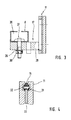
- the first screw connection 17 is shown in more detail in FIG. 3.
- the cantilever arm 8 has a profile which is double C-shaped in cross-section, into which the head of a hammer head screw, designated overall by 27, engages.
- the nut 30, which is supported by a washer 29 and is screwed onto this screw 27, rests on a transverse web, designated overall by 28, which is fixed on the actual mounting part 11. By loosening the nut 30, the mounting member 11 can be pivoted about the hinge 26 ( Figures 1 and 2).
- the mounting part 11 also has a guide device, generally designated 31, for the cable 15, which is provided with an endless roller chain 32 for guiding the cable of the hoist, the upper strand of which extends into the projecting region 12 of the motor part 11 and is continuous from a vertical direction is deflected in a horizontal direction. Furthermore, the horizontal area is at least up to the mounting position for the shaft bearing and the drive, which is located above the cantilever arm 8 of the wall bracket 5.
- the lower run of the roller chain can run freely or be tensioned using a chain tensioner.
- the roller chain 32 is guided on a sheet metal web designated 33 in total (FIG. 4).
Landscapes
- Engineering & Computer Science (AREA)
- Structural Engineering (AREA)
- Architecture (AREA)
- Civil Engineering (AREA)
- Operating, Guiding And Securing Of Roll- Type Closing Members (AREA)
- Forklifts And Lifting Vehicles (AREA)
- Perforating, Stamping-Out Or Severing By Means Other Than Cutting (AREA)
- Surgical Instruments (AREA)
- Power-Operated Mechanisms For Wings (AREA)
- Types And Forms Of Lifts (AREA)
- Spray Control Apparatus (AREA)
- Input Circuits Of Receivers And Coupling Of Receivers And Audio Equipment (AREA)
- Techniques For Improving Reliability Of Storages (AREA)
- Bidet-Like Cleaning Device And Other Flush Toilet Accessories (AREA)
- Telephone Function (AREA)
- Vehicle Body Suspensions (AREA)
- Supplying Of Containers To The Packaging Station (AREA)
Priority Applications (1)
| Application Number | Priority Date | Filing Date | Title |
|---|---|---|---|
| AT87103591T ATE64173T1 (de) | 1986-03-27 | 1987-03-12 | Montagegeraet. |
Applications Claiming Priority (2)
| Application Number | Priority Date | Filing Date | Title |
|---|---|---|---|
| DE19863610590 DE3610590A1 (de) | 1986-03-27 | 1986-03-27 | Montagegeraetschaft |
| DE3610590 | 1986-03-27 |
Publications (3)
| Publication Number | Publication Date |
|---|---|
| EP0238944A2 EP0238944A2 (de) | 1987-09-30 |
| EP0238944A3 EP0238944A3 (en) | 1988-03-02 |
| EP0238944B1 true EP0238944B1 (de) | 1991-06-05 |
Family
ID=6297498
Family Applications (1)
| Application Number | Title | Priority Date | Filing Date |
|---|---|---|---|
| EP87103591A Expired - Lifetime EP0238944B1 (de) | 1986-03-27 | 1987-03-12 | Montagegerät |
Country Status (4)
| Country | Link |
|---|---|
| EP (1) | EP0238944B1 (cg-RX-API-DMAC7.html) |
| AT (1) | ATE64173T1 (cg-RX-API-DMAC7.html) |
| DE (2) | DE3610590A1 (cg-RX-API-DMAC7.html) |
| DK (1) | DK168232B1 (cg-RX-API-DMAC7.html) |
Families Citing this family (5)
| Publication number | Priority date | Publication date | Assignee | Title |
|---|---|---|---|---|
| DE10127015A1 (de) * | 2001-01-12 | 2002-07-18 | Hoermann Kg Dissen | Montagevorrichtung zum Anheben eines Panzers eines Rolltors sowie Verwendung derselben |
| PL351581A1 (en) | 2001-01-12 | 2002-07-15 | Hoermann Kg Dissen | Device for and method of installing a rolled gate |
| GB2403206B (en) * | 2003-05-31 | 2006-06-28 | Rsl Bristol Ltd | Roller shutter assembly installation |
| DE102006046008B3 (de) * | 2006-09-28 | 2008-04-30 | Hörmann Kg Dissen | Montageverfahren für Rolltor und ein solches Rolltor |
| DE102010031733A1 (de) | 2010-07-21 | 2012-01-26 | Hörmann KG Antriebstechnik | Montageverfahren und Montagehilfsgerät für ein Rolltor |
Family Cites Families (2)
| Publication number | Priority date | Publication date | Assignee | Title |
|---|---|---|---|---|
| US3672492A (en) * | 1971-02-09 | 1972-06-27 | North American Door Corp | Factory-assembled overhead door |
| FR2550270B1 (fr) * | 1983-08-05 | 1988-06-03 | Accoplas Fermetures | Dispositif pour le montage et le reglage de l'arbre d'enroulement d'un volet roulant |
-
1986
- 1986-03-27 DE DE19863610590 patent/DE3610590A1/de active Granted
-
1987
- 1987-03-12 DE DE8787103591T patent/DE3770502D1/de not_active Expired - Fee Related
- 1987-03-12 AT AT87103591T patent/ATE64173T1/de not_active IP Right Cessation
- 1987-03-12 EP EP87103591A patent/EP0238944B1/de not_active Expired - Lifetime
- 1987-03-26 DK DK153287A patent/DK168232B1/da not_active IP Right Cessation
Also Published As
| Publication number | Publication date |
|---|---|
| DE3610590A1 (de) | 1987-10-01 |
| ATE64173T1 (de) | 1991-06-15 |
| DK153287A (da) | 1987-09-28 |
| EP0238944A2 (de) | 1987-09-30 |
| DK153287D0 (da) | 1987-03-26 |
| EP0238944A3 (en) | 1988-03-02 |
| DK168232B1 (da) | 1994-02-28 |
| DE3770502D1 (de) | 1991-07-11 |
| DE3610590C2 (cg-RX-API-DMAC7.html) | 1989-05-03 |
Similar Documents
| Publication | Publication Date | Title |
|---|---|---|
| EP0501140A1 (de) | In einem Aufzugsschacht verfahrbares Montagegerüst zur Montage von Schachtausrüstung | |
| EP0238944B1 (de) | Montagegerät | |
| DE102009058268A1 (de) | Kran und Verfahren zum Anheben eines Rotors | |
| DE19812959A1 (de) | Hubvorrichtung, insbesondere zum Einbau in Möbeln | |
| DE4209535C2 (de) | Hebevorrichtung für ein abnehmbares Stahlverdeck (Hardtop) eines Kraftfahrzeugs | |
| DE2406330A1 (de) | Vorrichtung zum ein- und ausbau des antriebsaggregates von kettenfahrzeugen | |
| DE8608523U1 (de) | Montagegerätschaft | |
| DE3801057A1 (de) | Transportvorrichtung fuer eine haengefoerdervorrichtung | |
| DE2925955A1 (de) | Anordnung zum einrammen von fussstuetzen fuer maste in die erde | |
| DE2650697A1 (de) | Abschleppkran fuer kraftfahrzeuge | |
| EP0675261A1 (de) | Rolltor mit einem flexiblen Torblatt | |
| DE2811505C2 (de) | Entspeicherungskratzer | |
| DE102022128047B3 (de) | Vorrichtung und Verfahren zur Bearbeitung einer Oberfläche mittels eines Strahls oder Strahlen eines Strahlguts | |
| DE9406439U1 (de) | Vorrichtung zum selbsttätigen Anheben zum Aufhängen eines Elektrokettenzuges | |
| DE3428678A1 (de) | Vorrichtung zum halten eines umfangsseitigen schalbretts einer deckenschalung | |
| AT403675B (de) | Hebevorrichtung an einem holzspaltgerät | |
| DE3015338A1 (de) | Vorrichtung zum handhaben von containern | |
| DE1242349B (de) | Vorrichtung zum Einbauen unverglaster Fensterrahmen in Gebaeuden | |
| DE8136572U1 (de) | Vorrichtung zum umscheren des hubseils bei kranen | |
| DE2326400C2 (de) | Außenbefahranlage | |
| DE1684298C3 (de) | Auf einer Schiene verfahrbare Laufkatze zum Tragen einer Arbeitsbühne | |
| DE927414C (de) | Parallel zu Gebaeudewaenden verfahrbare, mittels Winde anhebbare Arbeitsbuehne | |
| DD154381A1 (de) | Verfahren und vorrichtung zum stellen von stahlblechschornsteinen | |
| DE1531140C (de) | Fahrzeugkran | |
| DE9208259U1 (de) | Transportpalette für Seecontainer |
Legal Events
| Date | Code | Title | Description |
|---|---|---|---|
| PUAI | Public reference made under article 153(3) epc to a published international application that has entered the european phase |
Free format text: ORIGINAL CODE: 0009012 |
|
| AK | Designated contracting states |
Kind code of ref document: A2 Designated state(s): AT BE CH DE ES FR GB GR IT LI LU NL SE |
|
| RBV | Designated contracting states (corrected) |
Designated state(s): AT BE CH DE FR GB IT LI NL SE |
|
| PUAL | Search report despatched |
Free format text: ORIGINAL CODE: 0009013 |
|
| AK | Designated contracting states |
Kind code of ref document: A3 Designated state(s): AT BE CH DE FR GB IT LI NL SE |
|
| 17P | Request for examination filed |
Effective date: 19880518 |
|
| 17Q | First examination report despatched |
Effective date: 19890227 |
|
| GRAA | (expected) grant |
Free format text: ORIGINAL CODE: 0009210 |
|
| AK | Designated contracting states |
Kind code of ref document: B1 Designated state(s): AT BE CH DE FR GB IT LI NL SE |
|
| REF | Corresponds to: |
Ref document number: 64173 Country of ref document: AT Date of ref document: 19910615 Kind code of ref document: T |
|
| REF | Corresponds to: |
Ref document number: 3770502 Country of ref document: DE Date of ref document: 19910711 |
|
| ET | Fr: translation filed | ||
| ITF | It: translation for a ep patent filed | ||
| GBT | Gb: translation of ep patent filed (gb section 77(6)(a)/1977) | ||
| PLBE | No opposition filed within time limit |
Free format text: ORIGINAL CODE: 0009261 |
|
| STAA | Information on the status of an ep patent application or granted ep patent |
Free format text: STATUS: NO OPPOSITION FILED WITHIN TIME LIMIT |
|
| 26N | No opposition filed | ||
| EAL | Se: european patent in force in sweden |
Ref document number: 87103591.1 |
|
| PGFP | Annual fee paid to national office [announced via postgrant information from national office to epo] |
Ref country code: SE Payment date: 20000307 Year of fee payment: 14 |
|
| PGFP | Annual fee paid to national office [announced via postgrant information from national office to epo] |
Ref country code: BE Payment date: 20000331 Year of fee payment: 14 |
|
| PG25 | Lapsed in a contracting state [announced via postgrant information from national office to epo] |
Ref country code: SE Free format text: LAPSE BECAUSE OF NON-PAYMENT OF DUE FEES Effective date: 20010313 |
|
| PGFP | Annual fee paid to national office [announced via postgrant information from national office to epo] |
Ref country code: AT Payment date: 20010314 Year of fee payment: 15 |
|
| PGFP | Annual fee paid to national office [announced via postgrant information from national office to epo] |
Ref country code: NL Payment date: 20010330 Year of fee payment: 15 |
|
| PG25 | Lapsed in a contracting state [announced via postgrant information from national office to epo] |
Ref country code: BE Free format text: LAPSE BECAUSE OF NON-PAYMENT OF DUE FEES Effective date: 20010331 |
|
| BERE | Be: lapsed |
Owner name: HORMANN K.G. BIELEFELD Effective date: 20010331 |
|
| EUG | Se: european patent has lapsed |
Ref document number: 87103591.1 |
|
| REG | Reference to a national code |
Ref country code: GB Ref legal event code: IF02 |
|
| PG25 | Lapsed in a contracting state [announced via postgrant information from national office to epo] |
Ref country code: AT Free format text: LAPSE BECAUSE OF NON-PAYMENT OF DUE FEES Effective date: 20020312 |
|
| PG25 | Lapsed in a contracting state [announced via postgrant information from national office to epo] |
Ref country code: NL Free format text: LAPSE BECAUSE OF NON-PAYMENT OF DUE FEES Effective date: 20021001 |
|
| NLV4 | Nl: lapsed or anulled due to non-payment of the annual fee |
Effective date: 20021001 |
|
| PGFP | Annual fee paid to national office [announced via postgrant information from national office to epo] |
Ref country code: GB Payment date: 20030305 Year of fee payment: 17 |
|
| PG25 | Lapsed in a contracting state [announced via postgrant information from national office to epo] |
Ref country code: GB Free format text: LAPSE BECAUSE OF NON-PAYMENT OF DUE FEES Effective date: 20040312 |
|
| PGFP | Annual fee paid to national office [announced via postgrant information from national office to epo] |
Ref country code: CH Payment date: 20040315 Year of fee payment: 18 |
|
| PGFP | Annual fee paid to national office [announced via postgrant information from national office to epo] |
Ref country code: DE Payment date: 20040329 Year of fee payment: 18 |
|
| PGFP | Annual fee paid to national office [announced via postgrant information from national office to epo] |
Ref country code: FR Payment date: 20040330 Year of fee payment: 18 |
|
| GBPC | Gb: european patent ceased through non-payment of renewal fee |
Effective date: 20040312 |
|
| PG25 | Lapsed in a contracting state [announced via postgrant information from national office to epo] |
Ref country code: IT Free format text: LAPSE BECAUSE OF NON-PAYMENT OF DUE FEES;WARNING: LAPSES OF ITALIAN PATENTS WITH EFFECTIVE DATE BEFORE 2007 MAY HAVE OCCURRED AT ANY TIME BEFORE 2007. THE CORRECT EFFECTIVE DATE MAY BE DIFFERENT FROM THE ONE RECORDED. Effective date: 20050312 |
|
| PG25 | Lapsed in a contracting state [announced via postgrant information from national office to epo] |
Ref country code: LI Free format text: LAPSE BECAUSE OF NON-PAYMENT OF DUE FEES Effective date: 20050331 Ref country code: CH Free format text: LAPSE BECAUSE OF NON-PAYMENT OF DUE FEES Effective date: 20050331 |
|
| PG25 | Lapsed in a contracting state [announced via postgrant information from national office to epo] |
Ref country code: DE Free format text: LAPSE BECAUSE OF NON-PAYMENT OF DUE FEES Effective date: 20051001 |
|
| REG | Reference to a national code |
Ref country code: CH Ref legal event code: PL |
|
| PG25 | Lapsed in a contracting state [announced via postgrant information from national office to epo] |
Ref country code: FR Free format text: LAPSE BECAUSE OF NON-PAYMENT OF DUE FEES Effective date: 20051130 |
|
| REG | Reference to a national code |
Ref country code: FR Ref legal event code: ST Effective date: 20051130 |