EP0238937B1 - Sprech- und Höreinrichtung für Atemgeräte - Google Patents
Sprech- und Höreinrichtung für Atemgeräte Download PDFInfo
- Publication number
- EP0238937B1 EP0238937B1 EP87103515A EP87103515A EP0238937B1 EP 0238937 B1 EP0238937 B1 EP 0238937B1 EP 87103515 A EP87103515 A EP 87103515A EP 87103515 A EP87103515 A EP 87103515A EP 0238937 B1 EP0238937 B1 EP 0238937B1
- Authority
- EP
- European Patent Office
- Prior art keywords
- talking
- hearing device
- switching device
- respiratory gas
- speech
- Prior art date
- Legal status (The legal status is an assumption and is not a legal conclusion. Google has not performed a legal analysis and makes no representation as to the accuracy of the status listed.)
- Expired
Links
- 230000029058 respiratory gaseous exchange Effects 0.000 title description 26
- 230000000241 respiratory effect Effects 0.000 claims description 10
- 230000003434 inspiratory effect Effects 0.000 claims 1
- 235000014676 Phragmites communis Nutrition 0.000 description 6
- 230000009189 diving Effects 0.000 description 4
- 238000012544 monitoring process Methods 0.000 description 4
- 230000001629 suppression Effects 0.000 description 3
- 208000037656 Respiratory Sounds Diseases 0.000 description 2
- 230000005540 biological transmission Effects 0.000 description 2
- 239000000203 mixture Substances 0.000 description 2
- 239000000969 carrier Substances 0.000 description 1
- 238000004891 communication Methods 0.000 description 1
- 208000013407 communication difficulty Diseases 0.000 description 1
- 238000013016 damping Methods 0.000 description 1
- 230000000694 effects Effects 0.000 description 1
- 238000005516 engineering process Methods 0.000 description 1
- 230000033764 rhythmic process Effects 0.000 description 1
- XLYOFNOQVPJJNP-UHFFFAOYSA-N water Substances O XLYOFNOQVPJJNP-UHFFFAOYSA-N 0.000 description 1
Images
Classifications
-
- A—HUMAN NECESSITIES
- A62—LIFE-SAVING; FIRE-FIGHTING
- A62B—DEVICES, APPARATUS OR METHODS FOR LIFE-SAVING
- A62B18/00—Breathing masks or helmets, e.g. affording protection against chemical agents or for use at high altitudes or incorporating a pump or compressor for reducing the inhalation effort
- A62B18/08—Component parts for gas-masks or gas-helmets, e.g. windows, straps, speech transmitters, signal-devices
-
- B—PERFORMING OPERATIONS; TRANSPORTING
- B63—SHIPS OR OTHER WATERBORNE VESSELS; RELATED EQUIPMENT
- B63C—LAUNCHING, HAULING-OUT, OR DRY-DOCKING OF VESSELS; LIFE-SAVING IN WATER; EQUIPMENT FOR DWELLING OR WORKING UNDER WATER; MEANS FOR SALVAGING OR SEARCHING FOR UNDERWATER OBJECTS
- B63C11/00—Equipment for dwelling or working underwater; Means for searching for underwater objects
- B63C11/02—Divers' equipment
- B63C11/26—Communication means, e.g. means for signalling the presence of divers
Definitions
- the invention relates to a speaking and listening device for breathing devices with a noise suppression device, in which the device wearer is connected to a breathing gas supply that is independent of the environment.
- Such speaking and listening devices are used in particular by divers, pilots or people who need breathing apparatus during a rescue operation.
- the filters are designed for certain breathing gas mixtures and diving depth pressures, so that their area of application is limited to the specified operating conditions.
- the present invention is therefore based on the object of developing a speech and hearing device of the type mentioned in such a way that a suppression independent of acoustic signals, i.e. Damping or shutdown, the breathing noise of the equipment wearer is realized.
- the object is achieved in that a switching device that responds to the breathing gas flow is provided in the breathing gas line for the speaking and listening device to suppress breathing noises.
- the hearing and speaking device always suppresses the breathing noises, whereas during the speaking of a device wearer the speech and hearing device remains fully switched on because the breathing gas flow collapses during speaking and does not actuate the switching device.
- the speaking and listening device can be used regardless of the composition of the breathing gas, and the disturbing breathing noises are immediately suppressed without any switches having to be operated manually.
- the switching device can optionally be provided in the inhalation line or the exhalation line and in both breathing gas lines, or in a line section common to the inhalation and exhalation. In many cases, however, it is sufficient and proves to be expedient that the switching device is installed in the inhalation branch of the breathing gas supply. Thus, only the inhalation noises are suppressed, which are greater in volume than the exhalation noises and therefore overlap the speech frequencies more disturbingly than the quieter exhalation noises in contrast.
- the people speaking to one another can advantageously monitor one another by hearing the exhalation noises and thereby receiving information about the normal rhythm of life of the device wearer.
- the switching device consists of a piston sliding in a sleeve and held under pretensioning force. It is exposed to the flow of breathing gas, and an actuating element is located on its periphery for switching the speaking and listening device.
- the piston located in the sleeve is moved by the pressure of the inhalation or exhalation flow in the direction of the flow path against the biasing force exerted, for example, by a spring.
- the actuating element switches the contacts of the switching device of the device carrier in question, so that a transmission of breathing noises to the listening device carriers connected is interrupted or damped.
- the passage opening allows the breathing gas to flow freely through the switching device during one breath.
- the actuating element can be attached at any suitable location on the switching device. A suitable location is on the circumference of the piston and can be, for example, a permanent magnet that actuates a corresponding REED contact in the outer region of the sleeve.
- the passage opening is advantageously through a valve which releases the flow path element completed.
- a simple embodiment of this valve element consists of a spring-loaded poppet valve. The opening behavior of this additional valve is matched to the movement of the piston in such a way that it only opens when the actuating element has switched the speaking and listening device.
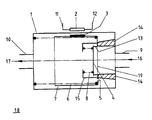
- the single figure shows a switching device (18) as it can be used in the exhalation branch of a breathing gas supply, for example for divers.
- the switching device with its inlet connection (9) and outlet connection (10) is inserted into the exhalation branch, so that the direction of flow of the respiratory gas flow is defined by the arrows (16, 17).
- a piston (7) is slidably received in an example cylindrical sleeve (1).
- the piston (7) is pressed against two flow lugs (14) against the direction of flow (16) by means of a spring (6).
- a passage opening (13) which is closed by a valve plate (4).
- a valve spring (8) which is supported against a valve housing (15), loads the valve plate (4).
- Two connections (11, 12) are led away from the REED contact (2), which lead to a speech and hearing device, not shown.
- the speech microphone of the speech and hearing device which is also not shown, is switched.
- the switching device is in the rest position, in which, for example, the permanent magnet (3) keeps the REED contact (2) closed, so that the speech microphone is switched for the transmission of speech signals.
- the speech signal is transmitted and the small amount of exhaled air of low flow velocity necessary for speaking enters the switching device via the inlet connection (9). Because of the low flow rate, the switching device is not actuated, but the exhaled air necessary for speaking can escape through the switching device to the outlet port (10) via a bypass opening (5). Only when the device wearer has stopped speaking and after he has possibly taken an inhalation will the exhaled air exhaled via the inlet connection (9) press against the face (19) of the piston (7) exposed to the respiratory gas flow at a high flow rate.
- the spring (6) and valve spring (8) are matched to one another in such a way that the spring force of the valve spring (8) keeps the valve plate (4) closed during the piston stroke, so that the piston (7) counteracts the spring force of the spring (6) in the direction the arrows (16, 17) is moved.
- the magnet (3) moves away from the REED contact (2) and opens it, so that the electrical signal circuit of the device microphone of the speech and hearing device is damped or interrupted. From this point on, speech signals and breathing noises are no longer transmitted.
- the pressure of the exhalation flow overcomes the spring force of the valve spring (8), so that the valve plate (4) lifts up from the passage opening (13) and releases a passage for the exhalation gas to the outlet port (10).
- the bypass opening (5) is dimensioned so small compared to the other opening cross-sections that the breathing gas flow that constantly escapes during exhalation is negligible and has no effect on the force conditions on the switching device.
Landscapes
- Health & Medical Sciences (AREA)
- Pulmonology (AREA)
- General Health & Medical Sciences (AREA)
- Business, Economics & Management (AREA)
- Emergency Management (AREA)
- Engineering & Computer Science (AREA)
- Mechanical Engineering (AREA)
- Ocean & Marine Engineering (AREA)
- Respiratory Apparatuses And Protective Means (AREA)
Description
- Die Erfindung betrifft eine Sprech- und Höreinrichtung für Atemgeräte mit einer Störgeräuschunterdrückungseinrichtung, bei denen der Geräteträger an eine von der Umgebung unabhängige Atemgasversorgung angeschlossen ist.
- Derartige Sprech- und Höreinrichtungen werden insbesondere bei Tauchern, bei Piloten oder bei Personen, die bei einem Rettungseinsatz Atemschutzgeräte benötigen, eingesetzt. Bei derartigen Einsätzen ist es häufig notwendig, daß beispielsweise mehrere Taucher unter Wasser sich miteinander verständigen können und diese gemeinsam an eine Überwachungsstation angeschlossen sind, von der aus eine überwachende Person sowohl mit jedem einzelnen Taucher als auch mit allen gemeinsam in Konferenzschaltung sprechen kann. Dabei erweist es sich als nachteilig, daß das Atemgeräusch des einen Tauchers die Sprachkommunikation mit einem anderen Taucher oder die gemeinsame Sprechverbindung zu der Überwachungsstation erheblich stört, so daß es zu Verständigungsschwierigkeiten kommt (DE-Z: Drägerheft, Nr. 244, September/ Oktober 1961, Seite 5403).
- Wenn alle Tauchermikrophone eingeschaltet sind und die überwachende Person an der Zentralstelle die Atemgeräusche aller Taucher gleichzeitig hört, ist eine Verständigung der Taucher untereinander und mit der Überwachungsperson erschwert oder gar nicht möglich. Insbesondere wenn die Tauchermikrophone in der Atemmaske oder im Taucherhelm angebracht sind, werden die Atemgeräusche übermäßig laut wiedergegeben. Wenn die betreffende Person auch noch körperliche Arbeitsleistung erbringen muß, werden die Atemzüge heftiger und schneller, so daß ein Gespräch zwischen zwei Teilnehmern durch die gleichzeitig hörbaren Atemgeräusche gestört wird.
- Ublicherweise werden auch elektrische Filter in den Sprechkreis eingeschaltet, die das schmalbandige Sprachsignal aus dem breitbandigen rauschähnlichen Atemgeräuschsignal herausfiltern sollen, weil innerhalb der Filterbandbreite der Energieanteil des Sprachsignals wesentlich höher ist. Nachteilig für diese Filterschaltungen ist es, daß durch akustische Resonanzen im Masken- bzw. Helmbereich des Geräteträgers auch das Atemgeräusch in seiner Bandbreite konzentriert wird. Dadurch ist die Rauschenergie innerhalb der Filterbandbreite so groß, daß keine befriedigende Atemgeräuschunterdrückung eintritt.
- Weiterhin sind die Filter auf bestimmte Atemgasgemische und Tauchtiefendrücke ausgelegt, so daß ihr Einsatzbereich auf die vorgegebenen Einsatzbedingungen beschränkt ist.
- Es ist z.B. aus "Sea Technology", Bd. 21, Nr. 12, Dez. 1980, Seiten 35, 36 bekannt, bei Tauchmaskenmikrophonen eine Unterdrückung des Maskenhintergrundgeräusches durch einen Sprachprozessor zu bewirken.
- Der vorliegenden Erfindung liegt somit die Aufgabe zugrunde, eine Sprech- und Höreinrichtung der genannten Art so weiterzubilden, daß eine von akustischen Signalen unabhängige Unterdrückung, d.h. Dämpfung oder Abschaltung, der Atmungsgeräusche des Geräteträgers verwirklicht wird.
- Die Lösung der Aufgabe erfolgt dadurch, daß in der Atemgasleitung eine auf den Atemgasstrom reagierende Schaltvorrichtung für die Sprech- und Höreinrichtung zur Unterdrückung der Atemgeräusche vorgesehen ist.
- Mit einer derartigen Anordnung der Schaltvorrichtung wird erreicht, daß die Hör- und Sprecheinrichtung stets die Atemgeräusche unterdrückt, wohingegen während des Sprechens eines Geräteträgers die Sprech- und Höreinrichtung voll angeschaltet bleibt, weil der Atemgasstrom während des Sprechens zusammenbricht und die Schaltvorrichtung nicht betätigt. Somit ist die Sprech- und Höreinrichtung unabhängig von der Zusammensetzung des Atemgases einsetzbar, und es werden unmittelbar die störenden Atemgeräusche unterdrückt, ohne daß irgendwelche Schalter manuell betätigt werden müssen.
- Die Schaltvorrichtung kann wahlweise in der Einatemleitung oder der Ausatemleitung sowie in beiden Atemgasleitungen, bzw. in einem der Ein- und Ausatmung gemeinsamen Leitungsabschnitt, vorgesehen sein. In vielen Fällen ist es jedoch ausreichend und erweist sich als zweckmäßig, daß die Schaltvorrichtung in den Einatemzweig der Atemgasversorgung eingebaut ist. Somit werden nur die Einatemgeräusche unterdrückt, welche in ihrer Lautstärke größer sind als die Ausatemgeräusche und deshalb die Sprechfrequenzen störender überlagern als die demgegenüber leiseren Ausatemgeräusche. Die miteinander sprechenden Personen können dabei vorteilhafterweise sich gegenseitig überwachen, indem sie die Ausatemgeräusche hören und dadurch Information über den normalen Lebensrhythmus des Geräteträgers erhalten.
- In weiterer Ausbildung der Erfindung ist vorgesehen, daß die Schaltvorrichtung aus einem in einer Hülse gleitenden, unter Vorspannkraft gehaltenen Kolben besteht. Er ist der Strömung des Atemgases ausgesetzt, und an seinem Umfang befindet sich zum Schalten der Sprech- und Höreinrichtung ein Betätigungselement. Der in der Hülse befindliche Kolben wird durch den Druck des Ein- oder Ausatemstromes in Richtung des Strömungsweges entgegen der beispielsweise durch eine Feder ausgeübten Vorspannkraft bewegt. Während dieser Bewegung schaltet das Betätigungselement die Kontakte der Schaltvorrichtung des betreffenden Geräteträgers, so daß eine Übertragung der Atemgeräusche zu den mithörenden verbundenen Geräteträgern unterbrochen oder bedämpft ist. Die Durchtrittsöffnung erlaubt ein freies Durchströmen des Atemgases während eines Atemzuges durch die Schaltvorrichtung hindurch. Das Betätigungselement kann an jeder dafür geeigneten Stelle der Schaltvorrichtung angebracht sein. Ein geeigneter Anbringungsort bietet sich an dem Umfang des Kolbens an und kann beispielsweise ein Permanentmagnet sein, der einen entsprechenden REED-Kontakt im Außenbereich der Hülse betätigt.
- Vorteilhafterweise ist die Durchtrittsöffnung durch ein den Strömungsweg freigebendes Ventilelement abgeschlossen. Eine einfache Ausführungsform dieses Ventilelementes besteht aus einem federbelasteten Tellerventil. Dieses zusätzliche Ventil ist in seinem Öffnungsverhalten so auf die Bewegung des Kolbens abgestimmt, daß es erst dann öffnet, wenn das Betätigungselement die Sprech- und Höreinrichtung geschaltet hat.
- Es ist zweckmäßig, eine die Schaltvorrichtung umgehende Öffnung vorzusehen, damit bei Einbau der Schaltvorrichtung in die Ausatemleitung der gegenüber dem Ausatemgasstrom wesentlich geringere Sprechgasstrom frei durch die Ausatemleitung strömen kann.
- Ein Ausführungsbeispiel der Erfindung wird anhand der schematischen Darstellung im folgenden näher erläutert.
- Die einzige Figur zeigt eine Schaltvorrichtung (18), wie sie in den Ausatemzweig einer Atemgasversorgung beispielsweise für Taucher eingesetzt werden kann. Dazu wird die Schaltvorrichtung mit ihrem Einlaßstutzen (9) und Auslaßstutzen (10) in den Ausatemzweig eingesetzt, so daß die Strömungsrichtung des Atemgasstromes durch die Pfeile (16, 17) festgelegt ist. In einer beispielsweise zylindrischen Hülse (1) ist ein Kolben (7) gleitend aufgenommen. Mittels einer Feder (6) wird der Kolben (7) entgegen der Strömungsrichtung (16) an zwei Stütznasen (14) angedrückt. In der der Strömungsrichtung (16) ausgesetzten Stirnfläche des Kolbens (7) befindet sich eine Durchtrittsöffnung (13), welche durch eine Ventilplatte (4) verschlossen ist. Eine Ventilfeder (8), welche sich gegen ein Ventilgehäuse (15) abstützt, belastet die Ventilplatte (4). An der Außenfläche des Kolbens (7), welcher zum Auslaßstutzen (10) hin offen ist, befindet sich ein Permanentmagnet (3), der zum Schalten eines ihm gegenüberliegenden an der Außenfläche der Hülse (1) angeordneten REED-Kontaktes (2) dient. Von dem REED-Kontakt (2) sind zwei Anschlüsse (11, 12) abgeführt, welche zu einer nicht dargestellten Sprech- und Höreinrichtung geführt sind. Dort wird bei entsprechender Betätigung des REED-Kontaktes (2) beispielsweise das ebenfalls nicht dargestellte Sprechmikrophon der Sprech- und Höreinrichtung geschaltet.
- In der dargestellten Form befindet sich die Schaltvorrichtung in Ruhestellung, bei welcher beispielsweise der Permanentmagnet (3) den REED-Kontakt (2) geschlossen hält, so daß das Sprechmikrophon zur Übertragung von Sprechsignalen geschaltet ist. Wenn der Geräteträger spricht, wird das Sprechsignal übertragen, und die zum Sprechen notwendige geringe Menge an Ausatemluft von geringer Strömungsgeschwindigkeit tritt über den Einlaßstutzen (9) in die Schaltvorrichtung ein. Wegen der geringen Strömungsgeschwindigkeit wird die Schaltvorrichtung nicht betätigt, sondern die beim Sprechen notwendige Ausatemluft kann über eine Umgehungsöffnung (5) durch die Schalteinrichtung zu dem Auslaßstutzen (10) entweichen. Erst wenn der Geräteträger aufgehört hat zu sprechen und nachdem er eventuell einen Einatemzug gemacht hat, wird die dann über den Einlaßstutzen (9) ausgeatmete Ausatemluft von hoher Strömungsgeschwindigkeit gegen die dem Atemgasstrom ausgesetzte Stirnfläche (19) des Kolbens (7) drücken. Feder (6) und Ventilfeder (8) sind derart aufeinander abgestimmt, daß die Federkraft der Ventilfeder (8) die Ventilplatte (4) während des Kolbenhubes geschlossen hält, so daß der Kolben (7) entgegen der Federkraft der Feder (6) in Richtung der Pfeile (16, 17) bewegt wird. Dabei entfernt sich der Magnet (3) von dem REED-Kontakt (2) und öffnet diesen, so daß der elektrische Signalkreis des Gerätemikrophons der Sprech- und Höreinrichtung bedämpft oder unterbrochen ist. Somit werden von diesem Zeitpunkt ab keine Sprechsignale und Atemgeräusche mehr übertragen. Am Ende des Kolbenhubes überwindet der Druck der Ausatemströmung die Federkraft der Ventilfeder (8), so daß sich die Ventilplatte (4) von der Durchtrittsöffnung (13) abhebt und einen Durchgang für das Ausatemgas zu dem Auslaßstutzen (10) freigibt. Während des gesamten Ausatemzuges bleibt somit der Kolben (7) in seiner Schaltstellung, während der das Sprechmikrophon bedämpft oder ausgeschaltet bleibt. Die Umgehuns- öffnung (5) ist im Vergleich zu den übrigen Öffnungsquerschnitten so gering dimensioniert, daß der während der Ausatmung ständig durch sie hinwegtretende Atemgasstrom vernachlässigbar ist und keine Auswirkungen auf die Kraftverhältnisse an der Schaltvorrichtung hat.
Claims (7)
Applications Claiming Priority (2)
| Application Number | Priority Date | Filing Date | Title |
|---|---|---|---|
| DE3609097 | 1986-03-19 | ||
| DE19863609097 DE3609097A1 (de) | 1986-03-19 | 1986-03-19 | Sprech- und hoereinrichtung fuer atemgeraete |
Publications (2)
| Publication Number | Publication Date |
|---|---|
| EP0238937A1 EP0238937A1 (de) | 1987-09-30 |
| EP0238937B1 true EP0238937B1 (de) | 1989-05-03 |
Family
ID=6296684
Family Applications (1)
| Application Number | Title | Priority Date | Filing Date |
|---|---|---|---|
| EP87103515A Expired EP0238937B1 (de) | 1986-03-19 | 1987-03-11 | Sprech- und Höreinrichtung für Atemgeräte |
Country Status (6)
| Country | Link |
|---|---|
| US (1) | US4799263A (de) |
| EP (1) | EP0238937B1 (de) |
| DE (2) | DE3609097A1 (de) |
| DK (1) | DK140087A (de) |
| FI (1) | FI865232L (de) |
| NO (1) | NO865081L (de) |
Cited By (1)
| Publication number | Priority date | Publication date | Assignee | Title |
|---|---|---|---|---|
| CN101508333B (zh) * | 2009-03-13 | 2011-01-19 | 武汉海王机电工程技术公司 | 机械式自动对接释放装置 |
Families Citing this family (34)
| Publication number | Priority date | Publication date | Assignee | Title |
|---|---|---|---|---|
| US5159641A (en) * | 1991-07-31 | 1992-10-27 | Figgie International, Inc. | Microphone circuit control mechanism for breathing apparatus |
| AU665082B2 (en) | 1992-05-29 | 1995-12-14 | Minnesota Mining And Manufacturing Company | Unidirectional fluid valve |
| US5325892A (en) * | 1992-05-29 | 1994-07-05 | Minnesota Mining And Manufacturing Company | Unidirectional fluid valve |
| US5307793A (en) * | 1992-06-29 | 1994-05-03 | Puritan-Bennett Corporation | Microphone signal attenuating apparatus for oxygen masks |
| WO1995009676A1 (en) * | 1993-10-01 | 1995-04-13 | Minnesota Mining And Manufacturing Company | Speech transmission adaptor for use with a respirator mask |
| US5990793A (en) * | 1994-09-02 | 1999-11-23 | Safety Tech Industries, Inc. | Firefighters integrated communication and safety system |
| US6121881A (en) * | 1994-09-02 | 2000-09-19 | Safety Tech Industries, Inc. | Protective mask communication devices and systems for use in hazardous environments |
| US5574794A (en) * | 1995-01-19 | 1996-11-12 | Earmark, Inc. | Microphone assembly for adhesive attachment to a vibratory surface |
| US5605145A (en) * | 1995-07-18 | 1997-02-25 | Puritan-Bennett Corporation | Microphone attenuation device for use in oxygen breathing masks |
| US5895537A (en) * | 1997-10-09 | 1999-04-20 | Campbell; Richard G. | Sonic welded gas mask and process |
| US6668822B2 (en) | 1998-01-14 | 2003-12-30 | John M. Monnich | Snorkel with improved purging system |
| US6318363B1 (en) * | 1998-01-14 | 2001-11-20 | John M. Monnich | Hydrodynamic and ergonomic snorkel |
| US7155388B2 (en) | 2004-06-30 | 2006-12-26 | Motorola, Inc. | Method and apparatus for characterizing inhalation noise and calculating parameters based on the characterization |
| US7254535B2 (en) * | 2004-06-30 | 2007-08-07 | Motorola, Inc. | Method and apparatus for equalizing a speech signal generated within a pressurized air delivery system |
| US7139701B2 (en) | 2004-06-30 | 2006-11-21 | Motorola, Inc. | Method for detecting and attenuating inhalation noise in a communication system |
| US7827987B2 (en) * | 2005-06-17 | 2010-11-09 | Nellcor Puritan Bennett Llc | Ball joint for providing flexibility to a gas delivery pathway |
| US7490608B2 (en) * | 2005-06-17 | 2009-02-17 | Nellcorr Puritan Bennett Llc | System and method for adjusting a gas delivery mask |
| US7849855B2 (en) * | 2005-06-17 | 2010-12-14 | Nellcor Puritan Bennett Llc | Gas exhaust system for a gas delivery mask |
| US7900630B2 (en) * | 2005-06-17 | 2011-03-08 | Nellcor Puritan Bennett Llc | Gas delivery mask with flexible bellows |
| US20070283952A1 (en) * | 2006-06-13 | 2007-12-13 | Mark Wilbur | Pressure sensing in masks |
| US20080053450A1 (en) * | 2006-08-31 | 2008-03-06 | Nellcor Puritan Bennett Incorporated | Patient interface assembly for a breathing assistance system |
| WO2010115169A1 (en) | 2009-04-02 | 2010-10-07 | Breathe Technologies, Inc. | Methods, systems and devices for non-invasive open ventilation for providing ventilation support |
| EP2617643A1 (de) * | 2012-01-18 | 2013-07-24 | Nederlandse Organisatie voor toegepast -natuurwetenschappelijk onderzoek TNO | Tauchwerkzeug |
| JP5592908B2 (ja) * | 2012-02-23 | 2014-09-17 | 興研株式会社 | 呼吸用保護具 |
| HK1213328A1 (zh) | 2012-09-24 | 2016-06-30 | Dolores Speech Products, Llc | 通信和語音增强系統 |
| US9943712B2 (en) | 2012-09-24 | 2018-04-17 | Dolores Speech Products Llc | Communication and speech enhancement system |
| US9289573B2 (en) | 2012-12-28 | 2016-03-22 | Covidien Lp | Ventilator pressure oscillation filter |
| US20140261405A1 (en) * | 2013-03-12 | 2014-09-18 | Marco Tekelenburg | Facepiece with noise reduction for communication |
| US11284201B2 (en) | 2017-04-24 | 2022-03-22 | Ataia Inc. | Systems and methods for communicating through a hard plastic mask |
| USD877886S1 (en) | 2018-04-24 | 2020-03-10 | Ataia Inc. | Communication device for hard plastic masks |
| US20200359137A1 (en) | 2017-04-24 | 2020-11-12 | Ataia Inc. | Systems and methods for communicating through a hard plastic mask |
| US10136225B2 (en) | 2017-04-24 | 2018-11-20 | Ataia Inc. | Systems and methods for communicating through a hard plastic mask |
| US10792449B2 (en) | 2017-10-03 | 2020-10-06 | Breathe Technologies, Inc. | Patient interface with integrated jet pump |
| USD954269S1 (en) | 2018-04-24 | 2022-06-07 | Ataia, Inc. | Communication device for hard plastic masks |
Family Cites Families (11)
| Publication number | Priority date | Publication date | Assignee | Title |
|---|---|---|---|---|
| US3123680A (en) * | 1964-03-03 | Mouthpiece for submarine use | ||
| FR362658A (fr) * | 1906-01-24 | 1906-07-04 | Walter Dresser | Casque pour scaphandriers |
| US1770821A (en) * | 1927-10-29 | 1930-07-15 | Troisi Fiorentino | Telephonic apparatus for deep-sea diving |
| DE701689C (de) * | 1938-05-25 | 1941-01-22 | Hagenuk Hanseatische Appbau Ge | Fernsprecheinrichtung an Gasschutzmasken |
| DE1101966B (de) * | 1957-08-23 | 1961-03-09 | Normalair Ltd | Sauerstoffatemschutzgeraet mit einer lungengesteuerten Sauerstoffzufuehrungsvorrichtung |
| US3415245A (en) * | 1965-03-08 | 1968-12-10 | Y2 Associates | Noise-suppression diving apparatus |
| GB1322434A (en) * | 1970-08-17 | 1973-07-04 | Suwa Seikosha Kk | Switchboards |
| US4154981A (en) * | 1977-12-16 | 1979-05-15 | The United States Of America As Represented By The Secretary Of The Navy | Telephone system for diver communication |
| US4183422A (en) * | 1978-01-12 | 1980-01-15 | Williams David W | Underwater communications device |
| US4527658A (en) * | 1984-07-31 | 1985-07-09 | Payne Philip W | Bubble silencer for an underwater voice communicator |
| US4527657A (en) * | 1984-07-31 | 1985-07-09 | Payne Philip W | Tapered tube impedance matching underwater voice communicator with bubble silencer |
-
1986
- 1986-03-19 DE DE19863609097 patent/DE3609097A1/de active Granted
- 1986-12-16 NO NO865081A patent/NO865081L/no unknown
- 1986-12-19 FI FI865232A patent/FI865232L/fi not_active IP Right Cessation
-
1987
- 1987-03-11 DE DE8787103515T patent/DE3760135D1/de not_active Expired
- 1987-03-11 EP EP87103515A patent/EP0238937B1/de not_active Expired
- 1987-03-18 US US07/027,344 patent/US4799263A/en not_active Expired - Fee Related
- 1987-03-18 DK DK140087A patent/DK140087A/da not_active Application Discontinuation
Cited By (1)
| Publication number | Priority date | Publication date | Assignee | Title |
|---|---|---|---|---|
| CN101508333B (zh) * | 2009-03-13 | 2011-01-19 | 武汉海王机电工程技术公司 | 机械式自动对接释放装置 |
Also Published As
| Publication number | Publication date |
|---|---|
| DE3760135D1 (en) | 1989-06-08 |
| DK140087D0 (da) | 1987-03-18 |
| EP0238937A1 (de) | 1987-09-30 |
| NO865081L (no) | 1987-09-21 |
| FI865232A7 (fi) | 1987-09-20 |
| NO865081D0 (no) | 1986-12-16 |
| FI865232A0 (fi) | 1986-12-19 |
| DE3609097A1 (de) | 1987-09-24 |
| DE3609097C2 (de) | 1989-09-21 |
| DK140087A (da) | 1987-09-20 |
| US4799263A (en) | 1989-01-17 |
| FI865232L (fi) | 1987-09-20 |
Similar Documents
| Publication | Publication Date | Title |
|---|---|---|
| EP0238937B1 (de) | Sprech- und Höreinrichtung für Atemgeräte | |
| DE69308621T2 (de) | Sprachübertragungsmembran und Ausatmungsventil | |
| DE69518582T2 (de) | Atemschutzmaske und Halterung für Mikrofon zur Verwendung davon | |
| DE3137113C2 (de) | Gerät für eine lokale, externe Kommunikation für Träger von Schutzhelmen und gegebenenfalls Masken | |
| DE60209742T2 (de) | Beatmungsmodul mit sprachübertragungs- und exhalationsventil | |
| US5307793A (en) | Microphone signal attenuating apparatus for oxygen masks | |
| TW333458B (en) | Valve for use in inhalation devices and method of assembling same | |
| DE3446771A1 (de) | Anordnung zur verbesserung der sprachuebertragung aus einer atemschutzmaske | |
| DE2838366A1 (de) | Warnsignalvorrichtung fuer atemschutzgeraete mit druckgasvorrat | |
| DE1708045A1 (de) | Atemschutzmaske mit Ausatemventilvorkammer und Sprechmembran | |
| DE3508130C2 (de) | ||
| DE102017010604A1 (de) | Kommunikationssysteme, Atemschutzmaske und Helm | |
| DE3013939C2 (de) | Mikrofonlautsprecher für Funksprechgeräte zur wahlweisen Benutzung für Schutzhelme und Atemschutzmasken | |
| EP0122878A2 (de) | Mundstück für Sporttaucher und Verwendung desselben | |
| DE1084767B (de) | Wechselsprechanlage fuer Tauch- und Grubenzwecke | |
| DE1126739B (de) | Atemschutzgeraet mit zwei ueber zwei Membranen lungengesteuerten Atemgaszufuehrungsventilen | |
| DE612888C (de) | Einrichtung an Gasschutzmasken mit Ausatemventil zur Erleichterung des Fernsprechens | |
| DE2953598A1 (de) | Stoergeraeuschkompensierte mikrofonschaltung | |
| DE155898C (de) | ||
| DE226297C (de) | ||
| DE185200C (de) | ||
| DE886468C (de) | Verschliessbare Einsprache fuer Mikrotelefone | |
| DE2230637A1 (de) | Hoer-sprech-garnitur | |
| DE1216371B (de) | Unterwasser-Lautsprecher | |
| DE1126738B (de) | Atemschutzgeraet mit lungengesteuertem Atemgaszufuehrungsventil, das an einen Druckminderer angeschlossen ist |
Legal Events
| Date | Code | Title | Description |
|---|---|---|---|
| PUAI | Public reference made under article 153(3) epc to a published international application that has entered the european phase |
Free format text: ORIGINAL CODE: 0009012 |
|
| 17P | Request for examination filed |
Effective date: 19870402 |
|
| AK | Designated contracting states |
Kind code of ref document: A1 Designated state(s): DE GB IT NL |
|
| 17Q | First examination report despatched |
Effective date: 19881007 |
|
| GRAA | (expected) grant |
Free format text: ORIGINAL CODE: 0009210 |
|
| ITF | It: translation for a ep patent filed | ||
| AK | Designated contracting states |
Kind code of ref document: B1 Designated state(s): DE GB IT NL |
|
| REF | Corresponds to: |
Ref document number: 3760135 Country of ref document: DE Date of ref document: 19890608 |
|
| GBT | Gb: translation of ep patent filed (gb section 77(6)(a)/1977) | ||
| PLBE | No opposition filed within time limit |
Free format text: ORIGINAL CODE: 0009261 |
|
| STAA | Information on the status of an ep patent application or granted ep patent |
Free format text: STATUS: NO OPPOSITION FILED WITHIN TIME LIMIT |
|
| PGFP | Annual fee paid to national office [announced via postgrant information from national office to epo] |
Ref country code: DE Payment date: 19900410 Year of fee payment: 4 |
|
| 26N | No opposition filed | ||
| PG25 | Lapsed in a contracting state [announced via postgrant information from national office to epo] |
Ref country code: NL Effective date: 19901001 |
|
| NLV4 | Nl: lapsed or anulled due to non-payment of the annual fee | ||
| PG25 | Lapsed in a contracting state [announced via postgrant information from national office to epo] |
Ref country code: GB Effective date: 19910311 |
|
| ITTA | It: last paid annual fee | ||
| GBPC | Gb: european patent ceased through non-payment of renewal fee | ||
| PG25 | Lapsed in a contracting state [announced via postgrant information from national office to epo] |
Ref country code: DE Effective date: 19920101 |
|
| PG25 | Lapsed in a contracting state [announced via postgrant information from national office to epo] |
Ref country code: IT Free format text: LAPSE BECAUSE OF NON-PAYMENT OF DUE FEES;WARNING: LAPSES OF ITALIAN PATENTS WITH EFFECTIVE DATE BEFORE 2007 MAY HAVE OCCURRED AT ANY TIME BEFORE 2007. THE CORRECT EFFECTIVE DATE MAY BE DIFFERENT FROM THE ONE RECORDED. Effective date: 20050311 |