EP0236388B1 - Process for coating tube-sheets or similar for condensers, coolers, heat exchangers or similar with an anti-corrosion agent - Google Patents
Process for coating tube-sheets or similar for condensers, coolers, heat exchangers or similar with an anti-corrosion agent Download PDFInfo
- Publication number
- EP0236388B1 EP0236388B1 EP86905275A EP86905275A EP0236388B1 EP 0236388 B1 EP0236388 B1 EP 0236388B1 EP 86905275 A EP86905275 A EP 86905275A EP 86905275 A EP86905275 A EP 86905275A EP 0236388 B1 EP0236388 B1 EP 0236388B1
- Authority
- EP
- European Patent Office
- Prior art keywords
- similar
- coating
- sheets
- plugs
- tube
- Prior art date
- Legal status (The legal status is an assumption and is not a legal conclusion. Google has not performed a legal analysis and makes no representation as to the accuracy of the status listed.)
- Expired - Lifetime
Links
Images
Classifications
-
- F—MECHANICAL ENGINEERING; LIGHTING; HEATING; WEAPONS; BLASTING
- F28—HEAT EXCHANGE IN GENERAL
- F28F—DETAILS OF HEAT-EXCHANGE AND HEAT-TRANSFER APPARATUS, OF GENERAL APPLICATION
- F28F19/00—Preventing the formation of deposits or corrosion, e.g. by using filters or scrapers
- F28F19/02—Preventing the formation of deposits or corrosion, e.g. by using filters or scrapers by using coatings, e.g. vitreous or enamel coatings
- F28F19/04—Preventing the formation of deposits or corrosion, e.g. by using filters or scrapers by using coatings, e.g. vitreous or enamel coatings of rubber; of plastics material; of varnish
-
- B—PERFORMING OPERATIONS; TRANSPORTING
- B29—WORKING OF PLASTICS; WORKING OF SUBSTANCES IN A PLASTIC STATE IN GENERAL
- B29C—SHAPING OR JOINING OF PLASTICS; SHAPING OF MATERIAL IN A PLASTIC STATE, NOT OTHERWISE PROVIDED FOR; AFTER-TREATMENT OF THE SHAPED PRODUCTS, e.g. REPAIRING
- B29C61/00—Shaping by liberation of internal stresses; Making preforms having internal stresses; Apparatus therefor
- B29C61/06—Making preforms having internal stresses, e.g. plastic memory
Definitions
- the invention relates to a method for coating tube sheets of condensers, coolers or heat exchangers with an anti-corrosion agent, plugs projecting outward beyond the end edges of the tubes being used in the ends of the tubes and being removed after the coating.
- the invention has for its object to provide a method for coating tube sheets of condensers, coolers or heat exchangers with an anti-corrosion agent, while avoiding the aforementioned disadvantages, which can be carried out in a simple and quick manner and ensures a perfect coating of the tube sheets .
- the anti-corrosion agent to form the coating of the tube sheets by pouring, spraying, etc. into the closed space, which is possible in a comparatively short time.
- the formwork resting on the outer sides of the plugs ensures that their outer end faces are not covered by the coating agent, so that they can be pulled out immediately after the formwork has been removed without a special grinding process.
- the plugs are provided with one or more bores into which a mandrel or the like. can be inserted.
- the tube ends can be expanded conically or in an arc shape, the shape of the outer contours of the plugs ensuring that the ends of the tubes projecting above the tube sheets are surrounded on all sides by the anticorrosive agent and trumpet-shaped inlets may result, which are special from a fluidic point of view prove advantageous.
- An epoxy resin is used as a corrosion protection agent, which guarantees a high level of corrosion protection.
- tube sheet 1 designates the tube sheet, for example a condenser, into which a multiplicity of tubes are inserted, of which only one wall of a tube 2 is shown.
- the tubes 2 are attached at their ends 3 in the tube sheet 1 by rolling.
- the tube sheet 1 has chamfers on the edges surrounding the bores for receiving the tubes 2, which are designated by 4.
- plastic stoppers 5 are inserted into them, which protrude beyond the end edges of the ends 3 of the tubes 2.
- one-piece or multi-part formwork 6 is placed, with fixed abutment against the outside of the stopper 5.
- clamping means are provided, which are indicated in the form of arrows 7. These exert a uniform pressure on all the plugs 5 inserted into the ends 3 of the tubes 2. Screw clamps, cylinder-piston units, etc. can be used as clamping devices.
- the one- or multi-part formwork 6 are designed so that they form a self-contained space 8 between the outside of the tube sheets 1 and the inside of the formwork 6.
- the space 8 is filled with anti-corrosion agent, so that there is a coating 9 on the outer sides of the tube sheets 1.
- the freely projecting ends 3 of the tubes 2 extend into the coating 9 so that they are enclosed on all sides by the anti-corrosion agent.
- the formwork 6 After hardening of the anti-corrosion agent and thus formation of the coating 9, the formwork 6 can be removed by loosening its clamping means 7, whereupon the exposed plug 5 can be removed easily and quickly.
Landscapes
- Engineering & Computer Science (AREA)
- Physics & Mathematics (AREA)
- Thermal Sciences (AREA)
- Mechanical Engineering (AREA)
- General Engineering & Computer Science (AREA)
- Application Of Or Painting With Fluid Materials (AREA)
- Preventing Corrosion Or Incrustation Of Metals (AREA)
- Laminated Bodies (AREA)
- Heat-Exchange Devices With Radiators And Conduit Assemblies (AREA)
- Protection Of Pipes Against Damage, Friction, And Corrosion (AREA)
Abstract
Description
Die Erfindung betrifft ein Verfahren zur Beschichtung von Rohrböden von Kondensatoren, Kühlern oder Wärmetauschern mit einem Korrosionsschutzmittel, wobei in den Enden der Rohre über deren Stirnkanten nach außen vorragende Stopfen eingesetzt werden, die nach der Beschichtung entfernt werden.The invention relates to a method for coating tube sheets of condensers, coolers or heat exchangers with an anti-corrosion agent, plugs projecting outward beyond the end edges of the tubes being used in the ends of the tubes and being removed after the coating.
Durch die GB-A-1 175 157 ist es bekannt, die Rohrböden von Kondensatoren, Kühlern oder Wärmetauschern gegen Korrosion mit einer Schicht aus Kunststoff zu versehen. Zu diesem Zwecke ist es erforderlich, nach Freilegen der Rohrböden die Enden der in diese eingesetzten Rohre aufzuweiten und deren Öffnungen mittels Kunststoffstopfen zu verschließen. Das Korrosionsschutzmittel wird von Hand als Spachtelmasse auf die Rohrböden aufgebracht, und zwar mit einer solchen Schichtdicke, daß die Stopfen überdeckt sind, um eine vollständige Beschichtung zu gewährleisten. Nach Aushärtung des Korrosionsschutzmittels wird dieses oberhalb der Stopfen abgeschliffen, so daß diese einzeln entfernt werden können. Die Anbringung von Schichten eines Korrosionsschutzmittels auf den Rohrböden hat sich bestens bewährt, jedoch erweist sich die Durchführung des vorerwähnten Verfahrens als vergleichsweise umständlich und damit sehr aufwendig.From GB-A-1 175 157 it is known to provide the tube sheets of condensers, coolers or heat exchangers with a layer of plastic against corrosion. For this purpose, after exposing the tube sheets, it is necessary to widen the ends of the tubes inserted into them and to close their openings by means of plastic plugs. The anti-corrosion agent is applied by hand as a filler to the tube sheets, with a layer thickness such that the plugs are covered to ensure complete coating. After the anti-corrosion agent has hardened, it is ground off above the stopper so that it can be removed individually. The application of layers of an anti-corrosion agent to the tube sheets has proven to be very effective, but the implementation of the aforementioned method has proven to be comparatively cumbersome and therefore very expensive.
Aus dem Bauwesen ist es bekannt, durch eine Schalung eine Hohlform des Baukörpers zu bilden, die mit flüssigen oder plastischen, später hart werdenden Baustoffen, beispielsweise Beton, ausgefüllt wird. Nach Erstarren der Füllung wird die Schalung entfernt und der Baukörper im Rohbau freigelegt.It is known from the construction industry to form a hollow form of the building body by means of a formwork, which is filled with liquid or plastic building materials, such as concrete, which become hard later. After the filling has solidified, the formwork is removed and the structure in the shell is exposed.
Von diesem Stand der Technik ausgehend liegt der Erfindung die Aufgabe zugrunde, unter Vermeidung vorerwähnter Nachteile ein Verfahren zur Beschichtung von Rohrböden von Kondensatoren, Kühlern oder Wärmetauschern mit einem Korrosionsschutzmittel zu schaffen, welches in einfacher und schneller Weise durchführbar ist und eine einwandfreie Beschichtung der Rohrböden gewährleistet.Starting from this prior art, the invention has for its object to provide a method for coating tube sheets of condensers, coolers or heat exchangers with an anti-corrosion agent, while avoiding the aforementioned disadvantages, which can be carried out in a simple and quick manner and ensures a perfect coating of the tube sheets .
Diese Aufgabe wird erfindungsgemäß durch folgende Verfahrensschritte gelöst:
- a) vor die Rohrböden werden vor der Beschichtung einoder mehrteilige Schalungen unter fester Anlage a die oberen Außenseiten der Stopfen und Bildung eines in sich geschlossenen Zwischenraumes zwischen Rohrböden und Schalung gesetzt;
- b) der Zwischenraum wird mit dem Korrosionsschutzmittel unter Bildung einer Beschichtung der Rohrböden verfüllt;
- c) nach einer bestimmten Zeit werden die Schalungen abgenommen.
- a) in front of the tube sheets, one-piece or multi-part formwork is placed under the fixed system a the upper outer sides of the plugs and the formation of a self-contained space between tube sheets and formwork;
- b) the space is filled with the anti-corrosion agent to form a coating on the tube sheets;
- c) after a certain time, the formwork is removed.
Auf diese Weise ist es möglich, das Korrosionsschutzmittel zur Ausbildung der Beschichtung der Rohrböden durch Giessen, Spritzen usw. in den geschlossenen Zwischenraum einzubringen, was in vergleichsweise kurzer Zeit möglich ist. Durch die auf den Außenseiten der Stopfen anliegenden Schalungen ist gewährleistet, daß deren äußere Stirnseiten nicht von dem Beschichtungsmittel bedeckt sind, so daß diese nach Entfernen der Schalungen ohne eines besonderen Schleifvorganges unmittelbar herausgezogen werden können. Um das Herausziehen zu erleichtern, sind die Stopfen mit einer oder mehreren Bohrungen versehen, in die ein Dorn od.dgl. eingesteckt werden kann. Bei Durchführung des erfindungsgemäßen Verfahrens wird somit eine gleichmäßige, einwandfreie Beschichtung in vergleichsweise kurzen Zeiten ermöglicht.In this way it is possible to introduce the anti-corrosion agent to form the coating of the tube sheets by pouring, spraying, etc. into the closed space, which is possible in a comparatively short time. The formwork resting on the outer sides of the plugs ensures that their outer end faces are not covered by the coating agent, so that they can be pulled out immediately after the formwork has been removed without a special grinding process. In order to facilitate pulling out, the plugs are provided with one or more bores into which a mandrel or the like. can be inserted. When carrying out the method according to the invention, a uniform, flawless coating is thus made possible in comparatively short times.
Die Rohrenden können konisch oder bogenförmig erweitert werden, wobei durch die Formgebung der Außenkonturen der Stopfen sichergestellt ist, daß die über die Rohrböden vorstehenden Enden der Rohre allseitig von dem Korrosionsschutzmittel umgeben sind und sich ggf. trompetenförmige Einläufe ergeben, welche sich aus strömungstechnischer Sicht als besonders vorteilhaft erweisen.The tube ends can be expanded conically or in an arc shape, the shape of the outer contours of the plugs ensuring that the ends of the tubes projecting above the tube sheets are surrounded on all sides by the anticorrosive agent and trumpet-shaped inlets may result, which are special from a fluidic point of view prove advantageous.
Als Korrosionsschutzmittel findet ein Epoxidharz Verwendung, welches einen hohen Kojb crrosionsschutz gewährleistet.An epoxy resin is used as a corrosion protection agent, which guarantees a high level of corrosion protection.
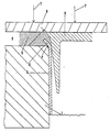
Ein Ausführungsbeispiel der Erfindung ist an Hand der Zeichnung näher erläutert, und zwar zeigt diese in vergrößerter Darstellung eine geschnittene Draufsicht eines Randbereiches eines Rohrendes in einem Rohrboden.An embodiment of the invention is explained in more detail with reference to the drawing, and this shows an enlarged representation of a sectional plan view of an edge region of a pipe end in a tube sheet.
Mit 1 ist der Rohrboden, beispielsweise eines Kondensators, bezeichnet, in den eine Vielzahl von Rohren eingesetzt ist von denen lediglich eine Wandung eines Rohres 2 dargestellt ist.1 designates the tube sheet, for example a condenser, into which a multiplicity of tubes are inserted, of which only one wall of a tube 2 is shown.
Die Rohre 2 sind an ihren Enden 3 im Rohrboden 1 durch Einwalzung befestigt. Der Rohrboden 1 weist an den die Bohrungen zur Aufnahme der Rohre 2 umgebenden Rändern Anfasungen auf, welche mit 4 bezeichnet sind.The tubes 2 are attached at their ends 3 in the tube sheet 1 by rolling. The tube sheet 1 has chamfers on the edges surrounding the bores for receiving the tubes 2, which are designated by 4.
Nach Aufweitung der Enden 3 der Rohre 2 werden in diese Stopfen 5 aus Kunststoff eingesetzt, welche die Stirnkanten der Enden 3 der Rohre 2 nach außen hin überragen.After the ends 3 of the tubes 2 have been widened, plastic stoppers 5 are inserted into them, which protrude beyond the end edges of the ends 3 of the tubes 2.
Vor die Rohrböden 1 sind ein oder mehrteilige Schalungen 6 gesetzt, und zwar unter fester Anlage an die Außenseiten der Stopfen 5. Zu diesem Zwecke sind Spannmittel vorgesehen, welche in Form von Pfeilen 7 angedeutet sind. Diese üben einen gleichmäßigen Druck auf sämtliche in die Enden 3 der Rohre 2 eingesetzte Stopfen 5 aus. Als Spannmittel können Schraubzwingen, Zylinder-Kolben-Einheiten usw. Verwendung finden.In front of the tube sheets 1, one-piece or multi-part formwork 6 is placed, with fixed abutment against the outside of the stopper 5. For this purpose, clamping means are provided, which are indicated in the form of arrows 7. These exert a uniform pressure on all the plugs 5 inserted into the ends 3 of the tubes 2. Screw clamps, cylinder-piston units, etc. can be used as clamping devices.
Die ein- oder mehrteiligen Schalungen 6 sind so ausgebildet, daß diese einen in sich geschlossenen Zwischenraum 8 zwischen den Außenseiten der Rohrböden 1 und den Innenseiten der Schalungen 6 ausbilden.The one- or multi-part formwork 6 are designed so that they form a self-contained space 8 between the outside of the tube sheets 1 and the inside of the formwork 6.
Der Zwischenraum 8 wird mit Korrosionsschutzmittel ausgefüllt, so daß sich auf den Außenseiten der Rohrböden 1 eine Beschichtung 9 ergibt. Die frei vorragenden Enden 3 der Rohre 2 erstrecken sich in die Beschichtung 9 hinein, so daß diese allseitig von dem Korrosionsschutzmittel umschlossen sind.The space 8 is filled with anti-corrosion agent, so that there is a coating 9 on the outer sides of the tube sheets 1. The freely projecting ends 3 of the tubes 2 extend into the coating 9 so that they are enclosed on all sides by the anti-corrosion agent.
Durch de Formgebung der Außenseiten der Stopfen 5 ist es möglich, die Ein- und Ausläufe in die Rohre 2 wunschgemäß zu gestalten, so daß diese, wie im dargestellten Ausführungsbeispiel, eine trompetenförmige Gestalt haben können.By shaping the outside of the Plug 5, it is possible to design the inlets and outlets in the tubes 2 as desired, so that they can have a trumpet-like shape, as in the illustrated embodiment.
Nach Aushärten des Korrosionsschutzmittels und damit Ausbildung der Beschichtung 9 kann die Schalung 6 durch Lösen ihrer Spannmittel 7 abgenommen werden, woraufhin de freiliegenden Stopfen 5 leicht und schnell entfernt werden können.After hardening of the anti-corrosion agent and thus formation of the coating 9, the formwork 6 can be removed by loosening its clamping means 7, whereupon the exposed plug 5 can be removed easily and quickly.
Mit Hilfe des erfindungsgemäßen Verfahrens ist es möglich, die Durchführung von Beschichtungsarbeiten an den Rohrböden von Kondensatoren, Kühlern oder Wärmetauschern wesentlich zu vereinfachen und zu beschleunigen sowie Stillstandszeiten erheblich zu verringern.With the aid of the method according to the invention, it is possible to significantly simplify and accelerate the carrying out of coating work on the tube sheets of condensers, coolers or heat exchangers and to considerably reduce downtimes.
Claims (5)
Priority Applications (1)
| Application Number | Priority Date | Filing Date | Title |
|---|---|---|---|
| AT86905275T ATE53451T1 (en) | 1985-08-31 | 1986-08-23 | PROCESS FOR COATING TUBE FLOORS OR THE LIKE. FROM CONDENSER, COOLERS, HEAT EXCHANGER OR THE LIKE. WITH AN ANTI-CORROSION AGENT. |
Applications Claiming Priority (2)
| Application Number | Priority Date | Filing Date | Title |
|---|---|---|---|
| DE3531150 | 1985-08-31 | ||
| DE19853531150 DE3531150A1 (en) | 1985-08-31 | 1985-08-31 | METHOD FOR COATING TUBE FLOORS OR THE LIKE. OF CONDENSERS, RADIATORS, HEAT EXCHANGERS OR THE LIKE. WITH AN ANTI-CORROSIVE AGENT |
Publications (2)
| Publication Number | Publication Date |
|---|---|
| EP0236388A1 EP0236388A1 (en) | 1987-09-16 |
| EP0236388B1 true EP0236388B1 (en) | 1990-06-06 |
Family
ID=6279833
Family Applications (1)
| Application Number | Title | Priority Date | Filing Date |
|---|---|---|---|
| EP86905275A Expired - Lifetime EP0236388B1 (en) | 1985-08-31 | 1986-08-23 | Process for coating tube-sheets or similar for condensers, coolers, heat exchangers or similar with an anti-corrosion agent |
Country Status (9)
| Country | Link |
|---|---|
| US (1) | US4795662A (en) |
| EP (1) | EP0236388B1 (en) |
| JP (1) | JPS63501655A (en) |
| KR (1) | KR880700231A (en) |
| AU (1) | AU593583B2 (en) |
| DE (2) | DE3531150A1 (en) |
| DK (1) | DK161787C (en) |
| ES (1) | ES2001275A6 (en) |
| WO (1) | WO1987001437A1 (en) |
Families Citing this family (11)
| Publication number | Priority date | Publication date | Assignee | Title |
|---|---|---|---|---|
| JPH0192386A (en) * | 1987-10-05 | 1989-04-11 | Hitachi Ltd | Hermetically sealed circulation type absorption refrigerator and absorbing solution for absorption refrigerator |
| SE468159B (en) * | 1991-03-25 | 1992-11-16 | Alfa Laval Thermal Ab | PROCEDURE FOR COATING HEAT TRANSFER PLATER IN A PLATE HEAT EXCHANGER WITH A LAYER OF SURFACE PROTECTIVE MATERIAL |
| US5472738A (en) * | 1991-03-25 | 1995-12-05 | Alfa Laval Thermal Ab | Method of providing heat transfer plates with a layer of a surface protecting material |
| DE4229177C1 (en) * | 1992-09-02 | 1994-04-21 | Testoterm Mestechnik Gmbh & Co | Gas cooler, for analytic purposes - has cooling block with drill hole face protected by plastic against aggressive gases, minimising overall dimensions, enhancing efficiency and minimising reference gas losses |
| DE59404431D1 (en) * | 1994-04-22 | 1997-11-27 | Kreiselmaier Ernst | Coating for tube sheets and coolant tubes of heat exchangers |
| US6254930B1 (en) | 1994-04-22 | 2001-07-03 | Richard Kreiselmaier | Coating tube plates and coolant tube |
| DE19534823C2 (en) * | 1995-09-20 | 2002-08-22 | Ruhr Oel Gmbh | Shell and tube heat exchangers |
| CA2635085A1 (en) | 2007-06-22 | 2008-12-22 | Johnson Controls Technology Company | Heat exchanger |
| IT1396816B1 (en) * | 2009-12-04 | 2012-12-14 | Gma S R L | PROCEDURE FOR COATING A MECHANICAL ORGAN, AND MECHANICALLY COVERED ORGAN |
| DE102010047589A1 (en) * | 2010-10-07 | 2012-04-12 | Techno-Coat Sa | Apparatus for internal treatment of pipes |
| DE102017100946A1 (en) | 2017-01-18 | 2018-07-19 | Techno-Coat Sa | Use of SiO2 coatings in water-carrying cooling systems |
Family Cites Families (6)
| Publication number | Priority date | Publication date | Assignee | Title |
|---|---|---|---|---|
| US1894957A (en) * | 1932-04-27 | 1933-01-24 | Babcock & Wilcox Co | Air heater |
| GB1175157A (en) * | 1966-03-19 | 1969-12-23 | Ernst Kreiselmaier | Improvements in or relating to Steam Condensers |
| DE1939665A1 (en) * | 1969-08-05 | 1971-02-25 | Exxon Research Engineering Co | Ammonia synthetsis iron-alkali metal-carrier- - catalyst |
| DE3152899C2 (en) * | 1981-10-29 | 1985-03-07 | Espo Wierden B.V., Wierden | Device for producing a component for a tubular heat exchanger |
| FR2549947B1 (en) * | 1983-07-29 | 1988-10-14 | Thermetic Ste Nle | HEAT EXCHANGER IN PARTICULAR FOR AIR DEHUMIDIFIER, AND DEHUMIDIFIER DEVICE PROVIDED WITH SUCH EXCHANGER |
| JPS60134197A (en) * | 1983-12-22 | 1985-07-17 | Toshiba Corp | Heat exchanger |
-
1985
- 1985-08-31 DE DE19853531150 patent/DE3531150A1/en active Granted
-
1986
- 1986-08-23 WO PCT/EP1986/000496 patent/WO1987001437A1/en active IP Right Grant
- 1986-08-23 US US07/047,436 patent/US4795662A/en not_active Expired - Lifetime
- 1986-08-23 DE DE8686905275T patent/DE3671797D1/en not_active Expired - Lifetime
- 1986-08-23 JP JP61504829A patent/JPS63501655A/en active Pending
- 1986-08-23 EP EP86905275A patent/EP0236388B1/en not_active Expired - Lifetime
- 1986-08-23 AU AU63371/86A patent/AU593583B2/en not_active Ceased
- 1986-08-28 ES ES8601439A patent/ES2001275A6/en not_active Expired
-
1987
- 1987-03-10 KR KR870700204A patent/KR880700231A/en not_active Application Discontinuation
- 1987-04-15 DK DK197887A patent/DK161787C/en active
Non-Patent Citations (1)
| Title |
|---|
| MOLD MAKING HANDBOOK FOR THE PLASTIC ENGINEER, Klaus Stöckhert, Collier Macmillan 1983, p. 160, 161 * |
Also Published As
| Publication number | Publication date |
|---|---|
| US4795662A (en) | 1989-01-03 |
| ES2001275A6 (en) | 1988-05-01 |
| DK161787C (en) | 1992-01-20 |
| EP0236388A1 (en) | 1987-09-16 |
| DK161787B (en) | 1991-08-12 |
| KR880700231A (en) | 1988-02-20 |
| AU593583B2 (en) | 1990-02-15 |
| DE3671797D1 (en) | 1990-07-12 |
| WO1987001437A1 (en) | 1987-03-12 |
| DK197887A (en) | 1987-04-15 |
| JPS63501655A (en) | 1988-06-23 |
| DK197887D0 (en) | 1987-04-15 |
| AU6337186A (en) | 1987-03-24 |
| DE3531150A1 (en) | 1987-03-05 |
| DE3531150C2 (en) | 1988-08-04 |
Similar Documents
| Publication | Publication Date | Title |
|---|---|---|
| EP0236388B1 (en) | Process for coating tube-sheets or similar for condensers, coolers, heat exchangers or similar with an anti-corrosion agent | |
| EP1635100B1 (en) | Lead-through device | |
| DE2935392A1 (en) | PIPE WITH A SEALING SURFACE PROVIDED WITH A PROTECTIVE ELEMENT | |
| CH686196A5 (en) | Spacer tube for double layered shuttering | |
| CH684648A5 (en) | Threaded sleeve for fastening structural elements provided with a tensioning bar designed in the form of a screw, and use of the same | |
| WO2009027543A2 (en) | Method for erecting a construction and masonry work anchoring system | |
| AT1204U1 (en) | SHAPED FORM FOR SUPPORTING COMPONENTS | |
| EP0241491A1 (en) | Form tool, in particular for processing plastic and synthetic resin concrete or mortar molding materials. | |
| DE2917578A1 (en) | METHOD AND DEVICE FOR PRODUCING HEAT-INSULATING COMPOSITE PROFILES | |
| DE2424353A1 (en) | Pipe connection with method of installation - sleeve fitting over pipe ends has locking ridges and two sealing rings | |
| DE2165896A1 (en) | PROCESS FOR PRODUCING A COMPOSITE BODY | |
| DE3340810A1 (en) | Process for producing prismatic components of reinforced concrete, in particular reinforced concrete supports, and an apparatus for carrying out the process | |
| DE2641682C3 (en) | Wall duct for cables, pipes or the like. | |
| CH715401A2 (en) | Device for preventing the transmission of sound through an opening or a production-related duct in a wall and a method for soundproof sealing of an opening or a production-related duct in a wall. | |
| DE678902C (en) | Process for the production of seamless T or cross tube pieces by pressing in a die | |
| DE1957402A1 (en) | Passage for house connections in walls for houses or similar buildings | |
| DE2546819A1 (en) | METHOD AND DEVICE FOR SEPARATING ROD OR TUBE MATERIAL | |
| DE3317182C2 (en) | Foam plastic cover for core pipes for the manufacture of precast concrete elements | |
| DE102005030470A1 (en) | Process to produce assembly frame for sealing packing for wall repair whereby pipe containing sealing material around one end is guided into mold cavity which is then filled with thermosetting material | |
| DE3204990C1 (en) | Method for manufacturing a high-temperature-resistant casing | |
| DE2758134C2 (en) | Process for the production of heat exchanger tubes!) With inner and outer longitudinal ribs | |
| DE2844544A1 (en) | MAST AND METHOD OF MANUFACTURING IT | |
| DE1808526C3 (en) | Device for forming seamless pipes made of asbestos cement | |
| DE3416862A1 (en) | Spacer for supporting shuttering elements, and process for erecting pressure-tight, concrete-filled assemblies | |
| DE102015009566B4 (en) | Method and device for a method for the production of prestressed precast concrete elements, in particular prestressed concrete sleepers or prestressed concrete sleepers |
Legal Events
| Date | Code | Title | Description |
|---|---|---|---|
| PUAI | Public reference made under article 153(3) epc to a published international application that has entered the european phase |
Free format text: ORIGINAL CODE: 0009012 |
|
| AK | Designated contracting states |
Kind code of ref document: A1 Designated state(s): AT BE CH DE FR GB IT LI LU NL SE |
|
| 17P | Request for examination filed |
Effective date: 19870814 |
|
| RAP1 | Party data changed (applicant data changed or rights of an application transferred) |
Owner name: DIPL.-ING. ERNST KREISELMAIER WASSER- UND METALL-C |
|
| 17Q | First examination report despatched |
Effective date: 19880630 |
|
| GRAA | (expected) grant |
Free format text: ORIGINAL CODE: 0009210 |
|
| AK | Designated contracting states |
Kind code of ref document: B1 Designated state(s): AT BE CH DE FR GB IT LI LU NL SE |
|
| REF | Corresponds to: |
Ref document number: 53451 Country of ref document: AT Date of ref document: 19900615 Kind code of ref document: T |
|
| REF | Corresponds to: |
Ref document number: 3671797 Country of ref document: DE Date of ref document: 19900712 |
|
| ITF | It: translation for a ep patent filed |
Owner name: BARZANO' E ZANARDO MILANO S.P.A. |
|
| ET | Fr: translation filed | ||
| GBT | Gb: translation of ep patent filed (gb section 77(6)(a)/1977) | ||
| RAP2 | Party data changed (patent owner data changed or rights of a patent transferred) |
Owner name: DIPL.-ING. ERNST KREISELMAIER GMBH & CO. WASSER- U |
|
| REG | Reference to a national code |
Ref country code: CH Ref legal event code: PFA Free format text: DIPL.-ING. ERNST KREISELMAIER GMBH & CO. WASSER- UND METALL-CHEMIE KG |
|
| NLT2 | Nl: modifications (of names), taken from the european patent patent bulletin |
Owner name: DIPL.-ING. ERNST KREISELMAIER GMBH & CO. WASSER- U |
|
| NLXE | Nl: other communications concerning ep-patents (part 3 heading xe) |
Free format text: IN PAT.BUL.21/90,PAGES 2936 AND 2956:CORR.:DIPL.-ING. ERNST KREISELMAIER GMBH & CO. WASSER-UND METALL-CHEMIE KG.PAT.BUL.01/91,PAGE 142 SHOULD BE DELETED |
|
| PLBE | No opposition filed within time limit |
Free format text: ORIGINAL CODE: 0009261 |
|
| STAA | Information on the status of an ep patent application or granted ep patent |
Free format text: STATUS: NO OPPOSITION FILED WITHIN TIME LIMIT |
|
| 26N | No opposition filed | ||
| ITTA | It: last paid annual fee | ||
| EPTA | Lu: last paid annual fee | ||
| EAL | Se: european patent in force in sweden |
Ref document number: 86905275.3 |
|
| PGFP | Annual fee paid to national office [announced via postgrant information from national office to epo] |
Ref country code: GB Payment date: 19970708 Year of fee payment: 12 |
|
| PGFP | Annual fee paid to national office [announced via postgrant information from national office to epo] |
Ref country code: SE Payment date: 19970714 Year of fee payment: 12 |
|
| PGFP | Annual fee paid to national office [announced via postgrant information from national office to epo] |
Ref country code: CH Payment date: 19970717 Year of fee payment: 12 |
|
| PGFP | Annual fee paid to national office [announced via postgrant information from national office to epo] |
Ref country code: BE Payment date: 19970731 Year of fee payment: 12 |
|
| PGFP | Annual fee paid to national office [announced via postgrant information from national office to epo] |
Ref country code: LU Payment date: 19970805 Year of fee payment: 12 |
|
| PGFP | Annual fee paid to national office [announced via postgrant information from national office to epo] |
Ref country code: NL Payment date: 19970831 Year of fee payment: 12 |
|
| PG25 | Lapsed in a contracting state [announced via postgrant information from national office to epo] |
Ref country code: LU Free format text: LAPSE BECAUSE OF NON-PAYMENT OF DUE FEES Effective date: 19980823 Ref country code: GB Free format text: LAPSE BECAUSE OF NON-PAYMENT OF DUE FEES Effective date: 19980823 |
|
| PG25 | Lapsed in a contracting state [announced via postgrant information from national office to epo] |
Ref country code: SE Free format text: LAPSE BECAUSE OF NON-PAYMENT OF DUE FEES Effective date: 19980824 |
|
| PG25 | Lapsed in a contracting state [announced via postgrant information from national office to epo] |
Ref country code: LI Free format text: LAPSE BECAUSE OF NON-PAYMENT OF DUE FEES Effective date: 19980831 Ref country code: CH Free format text: LAPSE BECAUSE OF NON-PAYMENT OF DUE FEES Effective date: 19980831 Ref country code: BE Free format text: LAPSE BECAUSE OF NON-PAYMENT OF DUE FEES Effective date: 19980831 |
|
| BERE | Be: lapsed |
Owner name: DIPL.-ING. ERNST KREISELMAIER G.M.B.H. & CO. WASS Effective date: 19980831 |
|
| PG25 | Lapsed in a contracting state [announced via postgrant information from national office to epo] |
Ref country code: NL Free format text: LAPSE BECAUSE OF NON-PAYMENT OF DUE FEES Effective date: 19990301 |
|
| GBPC | Gb: european patent ceased through non-payment of renewal fee |
Effective date: 19980823 |
|
| REG | Reference to a national code |
Ref country code: CH Ref legal event code: PL |
|
| EUG | Se: european patent has lapsed |
Ref document number: 86905275.3 |
|
| NLV4 | Nl: lapsed or anulled due to non-payment of the annual fee |
Effective date: 19990301 |
|
| PGFP | Annual fee paid to national office [announced via postgrant information from national office to epo] |
Ref country code: FR Payment date: 20050810 Year of fee payment: 20 |
|
| PGFP | Annual fee paid to national office [announced via postgrant information from national office to epo] |
Ref country code: AT Payment date: 20050811 Year of fee payment: 20 |
|
| PGFP | Annual fee paid to national office [announced via postgrant information from national office to epo] |
Ref country code: IT Payment date: 20050824 Year of fee payment: 20 |
|
| PGFP | Annual fee paid to national office [announced via postgrant information from national office to epo] |
Ref country code: DE Payment date: 20050902 Year of fee payment: 20 |