EP0235776B1 - Telefon, insbesondere Autotelefon - Google Patents
Telefon, insbesondere Autotelefon Download PDFInfo
- Publication number
- EP0235776B1 EP0235776B1 EP87102896A EP87102896A EP0235776B1 EP 0235776 B1 EP0235776 B1 EP 0235776B1 EP 87102896 A EP87102896 A EP 87102896A EP 87102896 A EP87102896 A EP 87102896A EP 0235776 B1 EP0235776 B1 EP 0235776B1
- Authority
- EP
- European Patent Office
- Prior art keywords
- earpiece
- headset
- telephone
- catch
- holder
- Prior art date
- Legal status (The legal status is an assumption and is not a legal conclusion. Google has not performed a legal analysis and makes no representation as to the accuracy of the status listed.)
- Expired - Lifetime
Links
- 230000014759 maintenance of location Effects 0.000 claims 3
- 230000000717 retained effect Effects 0.000 claims 1
- 210000003813 thumb Anatomy 0.000 description 5
- 230000006835 compression Effects 0.000 description 2
- 238000007906 compression Methods 0.000 description 2
- 230000005484 gravity Effects 0.000 description 2
- 241000287509 Piciformes Species 0.000 description 1
- 208000027418 Wounds and injury Diseases 0.000 description 1
- 230000001133 acceleration Effects 0.000 description 1
- 239000002775 capsule Substances 0.000 description 1
- 230000006378 damage Effects 0.000 description 1
- 238000011161 development Methods 0.000 description 1
- 230000018109 developmental process Effects 0.000 description 1
- 210000003811 finger Anatomy 0.000 description 1
- 230000001771 impaired effect Effects 0.000 description 1
- 238000007373 indentation Methods 0.000 description 1
- 208000014674 injury Diseases 0.000 description 1
- 238000003780 insertion Methods 0.000 description 1
- 230000037431 insertion Effects 0.000 description 1
- 230000009191 jumping Effects 0.000 description 1
Images


Classifications
-
- H—ELECTRICITY
- H04—ELECTRIC COMMUNICATION TECHNIQUE
- H04M—TELEPHONIC COMMUNICATION
- H04M1/00—Substation equipment, e.g. for use by subscribers
- H04M1/02—Constructional features of telephone sets
- H04M1/04—Supports for telephone transmitters or receivers
- H04M1/06—Hooks; Cradles
Definitions
- the invention relates to a telephone according to the preamble of claim 1, in particular a car telephone, wherein the telephone can be designed for two-way communication or for two-way communication.
- a telephone of this type is known from US-A 4,153,822.
- the headset is held on the bracket by two locking springs, the locking resistance of which can be overcome both when hanging up and when lifting by pushing or pulling on the headset.
- the two latching springs are arranged on two elevations supporting the mutually facing sides of the speaking and the earpiece and each engage in a recess in the speaking or earpiece. Because the headset is held on the bracket only by the detent spring force, there is a risk of it jumping out of the bracket in the event of an accident and injuring the car occupants.
- a different type of telephone is known from MOTOROLA technical developments, Volume 3, No. 1, March 1983, pp. 8/9, Schaumburg, Illinois (US), D. Irving: "Handset latch & delatch system”. He has a box-shaped holder for the earpiece of the headset (handset). The earpiece inserted into the box-shaped holder is on its front and the back is secured against train. On the front by a projection formed on the upper edge of the mounting wall, projecting inward beyond the box cavity, on the back by a spring-loaded pawl designed in the manner of a lock latch, which can be released by means of a release device. For this holder, the earpiece has a projection on its front and back. The front, obliquely upward projection engages under the projection of the bracket wall, the rear projection under the pawl.
- the headset To insert the earpiece into the holder, the headset must be tilted so that the earpiece is at the bottom and the mouthpiece is at the top. The earpiece is then inserted into the holder in such a way that its front projection comes to lie under the projection of the holder wall. The rear part of the headset is then pressed down until the pawl snaps onto the rear projection of the earpiece. To release the headset, the release device is pressed and the handset is initially pivoted upwards with the rear end (mouthpiece) so that the front projection of the earpiece releases from the projection of the holder wall, whereupon the handset can be pulled out of the holder in the inclined position .
- the insertion of the earpiece into the holder requires some attention because the headset has to be brought into a certain inclined position and inserted obliquely into the box-shaped holder while maintaining this position. This distracts the driver's attention from the traffic and there is also the risk that the driver simply places the headset next to the holder in traffic situations that require special attention. Then the handset is no longer secured and can injure the car occupants in an accident.
- the forces acting on the remaining part of the headset can exert a considerable torque in the event of an accident, so that the projection of the Bracket wall and the pawl and the projections of the earpiece act very high forces, the projections can break off and the headset is then no longer held.
- a similar telephone in which the headset is also secured against pulling on the holder, is known from FR-A 1 262 722.
- the holder has two L-shaped, swivel-mounted forks for the reception of the ear and speech cup.
- the upper fork is loaded by a spring, the lower fork can be secured with a locking device.
- the locking device is disengaged using a button.
- the headset can only be put on in a certain way, namely only by first hanging the earpiece into the upper fork. And only the one shell (here the mouthpiece) is secured to the bracket. The other shell (here the earpiece) is only resiliently held against train, but not locked against train.
- a telephone is also known in which the speaker is held on the holder by a resilient latching mechanism, the spring force of which can be overcome by pulling on the handset, so that it is the same as in US Pat. No. 4,153,822 can jump out of the holder in the event of an accident and there is a risk of injury.
- the invention has for its object to anchor the headset on the holder so that it can never detach from the holder and injure the car occupants in an accident, but that it can still be hung up and lifted effortlessly.
- Claim 2 describes a preferred embodiment.
- both the pawl and the pawl securing the earpiece engage easily and reliably when hanging up the headset, regardless of its position. H. regardless of whether the earpiece or the speech cup hits the holder first. This avoids the risk that the driver's attention is distracted from the traffic when the headset is put on and that the driver simply places the headset next to the holder in traffic situations that require special attention.
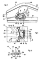
- the car telephone shown in FIGS. 1 and 2 has a holder 1 for the handset (handset) 2 to be fastened in the vehicle and designed as a support device 2.
- the mouthpiece 3 ie the housing part of the headset receiving the speech capsule
- the earpiece 4 are in the usual way across the handle of the headset.
- the holder 1 has a trough 13 and a support surface 14 for the speech and the earpiece 3 and 4.
- the trough 13 and the support surface 14 are delimited at the ends facing each other by an elevation 15 and 16.
- the walls of the elevations 15, 16 facing away from one another are designated by 23, 24.
- the wall 24 of the elevation 16 is adapted to the lower edge region of the earpiece 4 and is inclined to the vertical accordingly, so that the earpiece 4 when it is put on in FIG. 1 to the left (away from the storage recess 13 for the mouthpiece 3) and when it is lifted to the right slips.
- a pawl 30 which forms a lock for the mouthpiece 3 and which engages in a recess 32 of the mouthpiece 3 protrudes through the wall 23 of the elevation 15.
- One leg of the pawl 30 is arranged in the cavity of the elevation 15 and loaded by a spring 31, the other leg projecting through the wall 23 of the elevation 15 is chamfered at the free end in the manner of a lock latch.
- a lock for the earpiece 4 and a disengaging device are arranged in the hollow elevation 16.
- the lock has two spring-loaded latches or pawls 34, 35 designed in the manner of a lock latch, which engage through openings in the wall 24 into recesses 36 in the earpiece 4.
- the release device has a push button 37, 38 on each side of the elevation 16.
- Both buttons 37, 38 act on a slide engaging the foot of a carrier having the pawls 34, 35.
- the pawls 34, 35 can thus be disengaged both by pressing one key 37 and by pressing the other key 38.
- the disengaging device otherwise corresponds to the disengaging device of the embodiment of FIGS. 3-5, which is explained in more detail below, but has only one pushbutton.
- the headset 2 can be placed in a horizontal position and in a position inclined forwards or backwards.
- the pawl 30 is first pushed back against the force of the spring 31 and then clicks into the recess 32.
- the pawls 34, 35 are then pushed back through the lower edge of the earpiece 4 and latch into the recesses 36. The reverse applies if the headset 2 is placed on the earpiece 4 first.
- the handle (not shown) is gripped with the right or left hand and at the same time pressed with the thumb on the button 38 or 37, whereby the pawls 34, 35 disengage from the recesses 36.
- the button 37 or 38 can be pressed comfortably with one finger of the hand gripping the handle, which is due to the arrangement of the buttons 37, 38 on the two sides of the corner area between the handle and the earpiece 4 protruding elevation 16 is ensured.
- the recess 32 and the part of the pawl 30 engaging in it are designed in such a way that the mouthpiece 3 cannot be lifted, but after the pawls 34, 35 are disengaged and the earpiece 4 is slightly lifted out by a small horizontal movement component, it slips out of the pawl 30.
- the horizontal component of movement inevitably results from the fact that the earpiece 4 slides backwards over the sloping front wall 24 of the elevation 16 when the pawls 34, 35 are disengaged.
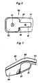
- the headset 80 is bent at an obtuse angle in the longitudinal direction and equipped with a bracket 81.
- the bend 89 is formed in the part of the handle 90 adjoining the earpiece 88.
- the bracket 81 is narrower than the earpiece 88 and extends straight from the edge of the wall 92 of the earpiece having the sound openings 91 over the corner region between the earpiece and the handle and over the bend 89 to the inside of the part adjoining the bend Part of the handle 90 that extends from the mouthpiece.
- the cutouts 86, 87 are arranged on the lower edge area of the earpiece 88 facing the mouthpiece 88 on both sides of the bracket 81.
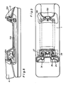
- the holder 82 is constructed in the same way as the holder 1 with a bearing recess for the mouthpiece, a pawl which engages in a recess or recess in the mouthpiece and a flat or slightly convex support surface 93 for the earpiece 88. It is the same width over its entire length and the earphone 80 tapers from the earpiece to the earpiece, so that the earpiece 88, which is of the same width as the holder 82, is flush with the edges of the holder and the narrower mouthpiece fits into the bearing recess.
- the wall 97 has two openings for the two pawls or snap bolts 84, 85, which are chamfered at the top in the manner of a lock latch and are formed on the legs of a U-shaped carrier 98.
- the upper wall of the elevation 96 has an indentation 94 which projects between the legs of the U-beam 98 and which receives the bracket 81 of the headset 80 placed thereon.
- the U-beam 98 has a trapezoidal foot 99 sliding on the plate 95 with a groove which is guided on a guide rail 100 arranged on the plate 95 in the longitudinal direction of the holder 82.
- One leg 101 of the trapezoidal foot 99 is flush with the upper side surface of the carrier 98 in FIG. 4 (left in FIG.
- the other leg 102 adjoins the front end (left in FIG. 4) of the groove and runs at an angle of 45 ° backwards away from the groove.
- a compression spring 104 supported on a support wall 103 presses the carrier 98 to the left in FIG. 4, as a result of which the inclined leg 102 is pressed against a correspondingly inclined edge surface of a slide 105 of the disengaging device.
- the slide 105 is slidably mounted in a rectangular recess 106 in the plate 95 perpendicular to the rail 100 against the force of a compression spring 107, which is arranged in a recess on the underside of the slide and one end of which is supported on the lower edge of the recess in FIG.
- the thickness of the slider 105 is dimensioned such that it protrudes from the recess 106 and the lower surface of the carrier 98 adjoining the foot 99 (right in FIG. 5) is supported on it in a sliding manner.
- an obliquely upwardly projecting, plate-shaped member 109 is formed, which carries a push button 110 which can be pressed through a recess in the side wall of the elevation 96.
- the push button 110 is expediently designed as a light button.
- the snap latches 84, 85 are pushed back from the edge of the earpiece wall 92, whereupon they snap into the cutouts 86, 87 under the action of the spring 104.
- the button 110 is pressed with the thumb of the hand that grips it, whereby the slide 105 is pushed forward against the force of the spring 107, and the oblique leg 102 of the support foot 99 on the oblique edge surface of the slide 105 against the force of the spring 104 slides back and disengage the latches 84, 85 from the recesses 86, 87.
- the thumb When the headset is lifted off, the thumb is placed on the handle part enclosed by the bracket 81, which, due to the large space created by the bend 89 between the bracket and the handle, not only happens effortlessly but also inevitably because the bracket causes a movement of the thumb out of the grip area enclosed by him.
- the bracket 81 secures then slip the headset 80 out of your hand. Because of the large space created by the bend 89 between the bracket 81 and the handle 90, the thumb can be left in the bracket when the headset is placed on the bracket.
- the disengagement of the mouthpiece 3 from the pawl 30 takes place in the manner described in connection with FIGS. 1 and 2.
- the two variants of the car telephone shown in FIGS. 8 to 11 differ from the exemplary embodiments in FIGS. 1-7 in that the disengaging device acts on both locks, that is to say also on the latch securing the mouthpiece 3.
- the pawl 133 securing the mouthpiece 3 is connected by a lever mechanism 130 to the carrier having the pawls or snap bolts 34, 35, so that when one of the keys 37, 38 is pressed, both the pawls 34, 35 as well as disengage the pawl 133.
- the pushbuttons 120, 121 are arranged approximately in the middle between the elevations 15 and 16 in lateral recesses in the holder 1 and each have a rod 131, 132 running in the longitudinal direction, both with those for disengaging the pawls 34, 35 serving slider (corresponding to the slider 105) and connected to corresponding, not shown in the drawing links for disengaging the pawl 133.
- the holder can be attached in any desired position in the vehicle and can be arranged instead of horizontally, for example also vertically.
- the pawl 30, on which the disengaging device does not act could also be arranged on the handset, in particular the mouthpiece, instead of on the holder.
- the lock on which the release device acts can also be arranged together with this on the handset, the key or buttons of the release device e.g. could be located on the underside of the handle of the headset. Compared to the arrangement of the disengaging device and the lock it applies to the holder, however, this has the disadvantage that the headset is heavier and its handiness is impaired.
- the fork or hook switch of an intercom car phone may be located on the bottom of the recess 94 receiving the bracket, and the talk button of an intercom car phone may be located on the inside of the handle of the handset between the bracket and the mouthpiece.
Landscapes
- Engineering & Computer Science (AREA)
- Signal Processing (AREA)
- Telephone Set Structure (AREA)
- Fittings On The Vehicle Exterior For Carrying Loads, And Devices For Holding Or Mounting Articles (AREA)
Priority Applications (1)
| Application Number | Priority Date | Filing Date | Title |
|---|---|---|---|
| AT87102896T ATE87782T1 (de) | 1983-10-11 | 1984-09-21 | Telefon, insbesondere autotelefon. |
Applications Claiming Priority (6)
| Application Number | Priority Date | Filing Date | Title |
|---|---|---|---|
| CH5528/83 | 1983-10-11 | ||
| CH552883 | 1983-10-11 | ||
| CH6678/83 | 1983-12-15 | ||
| CH667883 | 1983-12-15 | ||
| CH4080/84 | 1984-08-27 | ||
| CH408084 | 1984-08-27 |
Related Parent Applications (1)
| Application Number | Title | Priority Date | Filing Date |
|---|---|---|---|
| EP84111270.9 Division | 1984-09-21 |
Publications (3)
| Publication Number | Publication Date |
|---|---|
| EP0235776A2 EP0235776A2 (de) | 1987-09-09 |
| EP0235776A3 EP0235776A3 (en) | 1988-03-02 |
| EP0235776B1 true EP0235776B1 (de) | 1993-03-31 |
Family
ID=27174698
Family Applications (3)
| Application Number | Title | Priority Date | Filing Date |
|---|---|---|---|
| EP87102896A Expired - Lifetime EP0235776B1 (de) | 1983-10-11 | 1984-09-21 | Telefon, insbesondere Autotelefon |
| EP84111269A Expired EP0137382B1 (de) | 1983-10-11 | 1984-09-21 | Sprechhörer, insbesondere für ein Autotelefon |
| EP84111270A Expired EP0137383B1 (de) | 1983-10-11 | 1984-09-21 | Telefon, insbesondere Autotelefon |
Family Applications After (2)
| Application Number | Title | Priority Date | Filing Date |
|---|---|---|---|
| EP84111269A Expired EP0137382B1 (de) | 1983-10-11 | 1984-09-21 | Sprechhörer, insbesondere für ein Autotelefon |
| EP84111270A Expired EP0137383B1 (de) | 1983-10-11 | 1984-09-21 | Telefon, insbesondere Autotelefon |
Country Status (5)
| Country | Link |
|---|---|
| EP (3) | EP0235776B1 (enExample) |
| DE (4) | DE3486123D1 (enExample) |
| DK (1) | DK473984A (enExample) |
| FR (2) | FR2553247B3 (enExample) |
| NO (1) | NO844064L (enExample) |
Families Citing this family (8)
| Publication number | Priority date | Publication date | Assignee | Title |
|---|---|---|---|---|
| US4713836A (en) * | 1984-07-06 | 1987-12-15 | Nec Corporation | Telephone set structure having a member capable of being inserted in invertible position |
| DE3542424A1 (de) * | 1985-11-30 | 1987-06-04 | Ackermann Albert Gmbh Co | Haltevorrichtung |
| US4741034A (en) * | 1986-08-19 | 1988-04-26 | Motorola, Inc. | Receptacle for telephone handset |
| DE8710422U1 (de) * | 1987-07-29 | 1987-11-19 | Siemens AG, 1000 Berlin und 8000 München | Halterung für den Handapparat eines Telefons insbesondere Autotelefons |
| DE3742242A1 (de) * | 1987-12-12 | 1989-06-29 | Daimler Benz Ag | Telefon, insbesondere autotelefon |
| CH679963A5 (enExample) * | 1990-03-19 | 1992-05-15 | Andreas Peiker | |
| FI94701C (fi) * | 1990-12-04 | 1995-10-10 | Nokia Mobile Phones Ltd | Käyttölaitteen pidin |
| FR2810181A1 (fr) * | 2000-06-08 | 2001-12-14 | Sylvain Gleyal | Systeme de raccrochage/recharge pour telephone |
Family Cites Families (6)
| Publication number | Priority date | Publication date | Assignee | Title |
|---|---|---|---|---|
| FR1262722A (fr) * | 1960-04-22 | 1961-06-05 | Labo Cent Telecommunicat | Mécanisme d'accrochage de combiné téléphonique |
| DE2009599A1 (de) * | 1970-03-02 | 1971-09-16 | Tekade Felten & Guilleaume | Unfallsicheres Fernsprechteilnehmer gerat, insbesondere fur Fahrzeuganlagen |
| US3878343A (en) * | 1973-05-07 | 1975-04-15 | Dynalec Corp | Shockproof telephone set |
| US4153822A (en) * | 1977-03-08 | 1979-05-08 | Oki Electric Industry Co., Ltd. | Telephone set |
| FR2415394A1 (fr) * | 1978-01-24 | 1979-08-17 | Lepoix Louis | Telephone a commutation manuelle |
| DE3103368A1 (de) * | 1981-01-29 | 1982-09-02 | Elmeg Elektro-Mechanik Gmbh, 3150 Peine | "kompaktfernsprechapparat" |
-
1984
- 1984-09-21 DE DE8787102896T patent/DE3486123D1/de not_active Expired - Lifetime
- 1984-09-21 DE DE8484111269T patent/DE3471220D1/de not_active Expired
- 1984-09-21 EP EP87102896A patent/EP0235776B1/de not_active Expired - Lifetime
- 1984-09-21 DE DE8484111270T patent/DE3473108D1/de not_active Expired
- 1984-09-21 EP EP84111269A patent/EP0137382B1/de not_active Expired
- 1984-09-21 EP EP84111270A patent/EP0137383B1/de not_active Expired
- 1984-09-24 DE DE8428061U patent/DE8428061U1/de not_active Expired
- 1984-10-03 DK DK473984A patent/DK473984A/da not_active Application Discontinuation
- 1984-10-10 NO NO844064A patent/NO844064L/no unknown
- 1984-10-11 FR FR8415627A patent/FR2553247B3/fr not_active Expired
- 1984-10-11 FR FR8415628A patent/FR2553248B3/fr not_active Expired
Non-Patent Citations (1)
| Title |
|---|
| MOTOROLA Technical Developments, vol. 3, no. 1, March 1983, pages 8,9, Motorola Inc., Schaumburg, Illinois (US); D.E. Irving : "Handset latch & delatch system" * |
Also Published As
| Publication number | Publication date |
|---|---|
| FR2553247B3 (fr) | 1985-09-20 |
| FR2553248B3 (fr) | 1985-09-20 |
| NO844064L (no) | 1985-04-12 |
| EP0235776A2 (de) | 1987-09-09 |
| DE3471220D1 (en) | 1988-06-16 |
| DK473984A (da) | 1985-04-12 |
| EP0137383A3 (enExample) | 1985-06-05 |
| FR2553247A3 (fr) | 1985-04-12 |
| EP0235776A3 (en) | 1988-03-02 |
| EP0137383A2 (de) | 1985-04-17 |
| EP0137382A2 (de) | 1985-04-17 |
| DK473984D0 (da) | 1984-10-03 |
| DE3486123D1 (de) | 1993-05-06 |
| EP0137382A3 (en) | 1985-07-24 |
| DE3473108D1 (en) | 1988-09-01 |
| FR2553248A3 (fr) | 1985-04-12 |
| EP0137382B1 (de) | 1988-05-11 |
| EP0137383B1 (de) | 1988-07-27 |
| DE8428061U1 (de) | 1985-01-10 |
Similar Documents
| Publication | Publication Date | Title |
|---|---|---|
| DE4329692C2 (de) | Aufbau einer Rückhaltestange für eine Babyschaukel sowie Babyschaukel | |
| DE60204271T2 (de) | Halterung für ein Handgerät | |
| DE69919942T2 (de) | Befestigungsvorrichtung für einen Sicherheits-Kindersitz | |
| EP0235776B1 (de) | Telefon, insbesondere Autotelefon | |
| DE202005013523U1 (de) | Mobilgeräte-Klemmhalterung mit gedämpftem Freigabemechanismus | |
| US4723281A (en) | Automobile telephone | |
| DE2740200C2 (de) | Sicherheitsgurtschloß | |
| DE3715207A1 (de) | Schloss fuer einen sicherheitsgurt | |
| DE2729151A1 (de) | Verschlusstueck fuer eine sitzgurtschnalle | |
| DE2637075A1 (de) | Aus zunge und schloss bestehende kupplung zur verwendung vorzugsweise an einem sicherheitsgurt | |
| DE1557449B2 (de) | Verschlusschnalle | |
| DE4303247A1 (de) | Kindersicherheitssitz | |
| US4589674A (en) | Apparatus for facilitating a longitudinal adjustment of ski-binding parts | |
| DE1266552B (de) | Verschlussschnalle | |
| EP0404089B1 (de) | Gurtschloss für Gurtbandrückhaltesysteme | |
| DE1557427B1 (de) | Verschlussschnalle fuer einen Sicherheitsgurt | |
| DE4228632C1 (enExample) | ||
| DE102013217936B4 (de) | Griffstück-Höheneinstellmechanismus und zugehöriger Kinderwagen | |
| DE2105298B2 (de) | Verschlußschnalle für Sicherheitsgurte | |
| DE4413535A1 (de) | Kindersitzanordnung | |
| DE8428060U1 (de) | Sprechhörer, insbesondere für ein Autotelefon | |
| DE8230071U1 (de) | Gurtschloß für Sicherheitssysteme | |
| EP1023200B1 (de) | Armlehne für einen Fahrzeugsitz | |
| DE20017448U1 (de) | Mehrzweckkindersicherheitssitz | |
| DE29807598U1 (de) | Befestigungseinrichtung für ein Mobiltelefon |
Legal Events
| Date | Code | Title | Description |
|---|---|---|---|
| PUAI | Public reference made under article 153(3) epc to a published international application that has entered the european phase |
Free format text: ORIGINAL CODE: 0009012 |
|
| AC | Divisional application: reference to earlier application |
Ref document number: 137383 Country of ref document: EP |
|
| AK | Designated contracting states |
Kind code of ref document: A2 Designated state(s): AT CH DE FR GB IT LI NL SE |
|
| PUAL | Search report despatched |
Free format text: ORIGINAL CODE: 0009013 |
|
| AK | Designated contracting states |
Kind code of ref document: A3 Designated state(s): AT CH DE FR GB IT LI NL SE |
|
| 17P | Request for examination filed |
Effective date: 19880804 |
|
| 17Q | First examination report despatched |
Effective date: 19901005 |
|
| GRAA | (expected) grant |
Free format text: ORIGINAL CODE: 0009210 |
|
| ITF | It: translation for a ep patent filed | ||
| AC | Divisional application: reference to earlier application |
Ref document number: 137383 Country of ref document: EP |
|
| AK | Designated contracting states |
Kind code of ref document: B1 Designated state(s): AT CH DE FR GB IT LI NL SE |
|
| PG25 | Lapsed in a contracting state [announced via postgrant information from national office to epo] |
Ref country code: SE Effective date: 19930331 Ref country code: NL Effective date: 19930331 Ref country code: GB Effective date: 19930331 |
|
| REF | Corresponds to: |
Ref document number: 87782 Country of ref document: AT Date of ref document: 19930415 Kind code of ref document: T |
|
| REF | Corresponds to: |
Ref document number: 3486123 Country of ref document: DE Date of ref document: 19930506 |
|
| ET | Fr: translation filed | ||
| NLV1 | Nl: lapsed or annulled due to failure to fulfill the requirements of art. 29p and 29m of the patents act | ||
| PGFP | Annual fee paid to national office [announced via postgrant information from national office to epo] |
Ref country code: FR Payment date: 19930916 Year of fee payment: 10 |
|
| PG25 | Lapsed in a contracting state [announced via postgrant information from national office to epo] |
Ref country code: AT Effective date: 19930921 |
|
| PG25 | Lapsed in a contracting state [announced via postgrant information from national office to epo] |
Ref country code: LI Effective date: 19930930 Ref country code: CH Effective date: 19930930 |
|
| GBV | Gb: ep patent (uk) treated as always having been void in accordance with gb section 77(7)/1977 [no translation filed] |
Effective date: 19930331 |
|
| PLBE | No opposition filed within time limit |
Free format text: ORIGINAL CODE: 0009261 |
|
| STAA | Information on the status of an ep patent application or granted ep patent |
Free format text: STATUS: NO OPPOSITION FILED WITHIN TIME LIMIT |
|
| 26N | No opposition filed | ||
| REG | Reference to a national code |
Ref country code: CH Ref legal event code: PL |
|
| PG25 | Lapsed in a contracting state [announced via postgrant information from national office to epo] |
Ref country code: FR Effective date: 19950531 |
|
| REG | Reference to a national code |
Ref country code: FR Ref legal event code: ST |
|
| PGFP | Annual fee paid to national office [announced via postgrant information from national office to epo] |
Ref country code: DE Payment date: 20030919 Year of fee payment: 20 |