EP0235277B1 - Vorrichtung zum verbrennen oxidierbarer bestandteile in einem zu reinigenden trägergas - Google Patents
Vorrichtung zum verbrennen oxidierbarer bestandteile in einem zu reinigenden trägergas Download PDFInfo
- Publication number
- EP0235277B1 EP0235277B1 EP86905767A EP86905767A EP0235277B1 EP 0235277 B1 EP0235277 B1 EP 0235277B1 EP 86905767 A EP86905767 A EP 86905767A EP 86905767 A EP86905767 A EP 86905767A EP 0235277 B1 EP0235277 B1 EP 0235277B1
- Authority
- EP
- European Patent Office
- Prior art keywords
- tubes
- carrier gas
- heat exchanger
- gas
- burner
- Prior art date
- Legal status (The legal status is an assumption and is not a legal conclusion. Google has not performed a legal analysis and makes no representation as to the accuracy of the status listed.)
- Expired
Links
- 239000012159 carrier gas Substances 0.000 title claims abstract description 23
- 238000002485 combustion reaction Methods 0.000 claims abstract description 25
- 239000007789 gas Substances 0.000 claims description 25
- 238000010438 heat treatment Methods 0.000 claims 1
- 239000012476 oxidizable substance Substances 0.000 claims 1
- 230000008020 evaporation Effects 0.000 abstract description 2
- 238000001704 evaporation Methods 0.000 abstract description 2
- 239000000470 constituent Substances 0.000 description 5
- 239000000126 substance Substances 0.000 description 4
- 238000003466 welding Methods 0.000 description 4
- 230000015572 biosynthetic process Effects 0.000 description 3
- 238000010276 construction Methods 0.000 description 3
- 238000005299 abrasion Methods 0.000 description 2
- 206010016256 fatigue Diseases 0.000 description 2
- 238000009413 insulation Methods 0.000 description 2
- 238000000034 method Methods 0.000 description 2
- 230000009467 reduction Effects 0.000 description 2
- 239000000956 alloy Substances 0.000 description 1
- 229910045601 alloy Inorganic materials 0.000 description 1
- 238000009833 condensation Methods 0.000 description 1
- 230000005494 condensation Effects 0.000 description 1
- 238000005336 cracking Methods 0.000 description 1
- 230000001419 dependent effect Effects 0.000 description 1
- 230000003628 erosive effect Effects 0.000 description 1
- 238000009422 external insulation Methods 0.000 description 1
- 239000003546 flue gas Substances 0.000 description 1
- 239000012530 fluid Substances 0.000 description 1
- 238000004519 manufacturing process Methods 0.000 description 1
- 239000000463 material Substances 0.000 description 1
- 238000012856 packing Methods 0.000 description 1
- 239000002245 particle Substances 0.000 description 1
- 230000002093 peripheral effect Effects 0.000 description 1
- 230000001681 protective effect Effects 0.000 description 1
- 230000005855 radiation Effects 0.000 description 1
Images
Classifications
-
- F—MECHANICAL ENGINEERING; LIGHTING; HEATING; WEAPONS; BLASTING
- F23—COMBUSTION APPARATUS; COMBUSTION PROCESSES
- F23G—CREMATION FURNACES; CONSUMING WASTE PRODUCTS BY COMBUSTION
- F23G7/00—Incinerators or other apparatus for consuming industrial waste, e.g. chemicals
- F23G7/06—Incinerators or other apparatus for consuming industrial waste, e.g. chemicals of waste gases or noxious gases, e.g. exhaust gases
- F23G7/061—Incinerators or other apparatus for consuming industrial waste, e.g. chemicals of waste gases or noxious gases, e.g. exhaust gases with supplementary heating
- F23G7/065—Incinerators or other apparatus for consuming industrial waste, e.g. chemicals of waste gases or noxious gases, e.g. exhaust gases with supplementary heating using gaseous or liquid fuel
- F23G7/066—Incinerators or other apparatus for consuming industrial waste, e.g. chemicals of waste gases or noxious gases, e.g. exhaust gases with supplementary heating using gaseous or liquid fuel preheating the waste gas by the heat of the combustion, e.g. recuperation type incinerator
Definitions
- the invention relates to a device for burning oxidizable constituents in a carrier gas to be cleaned, comprising a gas inlet and a gas outlet, a burner followed by a high-speed mixing chamber, a combustion chamber and a heat exchanger with gas arranged around the high-speed mixing chamber, from the gas to be cleaned in cross-counterflow to the cleaned Gas flowed through pipes that are bent at one end.
- a corresponding device can be found in EP-A-0 040 690.
- the heat exchanger tubes on the hot side of the device that is to say in the area of the burner, are bent inwards and inserted in a drum concentrically surrounding the burner.
- this construction has the advantage that temperature-related different expansions of the individual tubes do not lead to damage such as e.g. B. lead to cracking.
- considerable manufacturing effort is required to weld the inwardly bent pipes to the drum, since the distances between the pipe ends are small.
- the drum itself cannot compensate for temperature-related heat exchanger pipe expansion, since a relatively thick wall is required so that the welding heat introduced during welding does not lead to shrinkage and warping of the drum, which would otherwise result in the pipe elbows being distorted.
- the heat exchanger tubes do not take part in the entire length of the heat exchange, since the bent ends are not directly flown by the hot flue gases, but rather are deflected and deflected by an inflow space in such a way that they do not hit the bent portions of the tubes. Furthermore, scaling occurs in the area of the pipe bends, since these are on the hottest side of the device. Scale formation can, however, lead to an erosion of the pipe wall thickness if the pipes in this area suffer particularly high changes in expansion speed. Such special expansion speed changes are usually process-related.
- the object of the present invention is to design a device of the type described above in such a way that the heat exchanger is secured with structurally simple means against expansions caused by temperature and fluctuations and surface damage.
- the object is achieved in that the heat exchanger tubes are bent outwards at their colder ends.
- This has the advantage that the pipe ends are arranged on a much larger circumferential surface compared to inwardly bent pipes, so that easier welding and thus also suitability for automatic machines is achieved.
- the welded ends can be at a considerably greater distance from one another, so that the jacket receiving the ends does not have to be an additional component such as a drum, compared to the prior art.
- the inner wall of an outer annular space is used as a fastening surface. through which the carrier gas containing the oxidizable constituents is guided from the inlet opening to the heat exchanger tubes.
- the wall material can be chosen thinner, so that the overall flexibility of the compensation area increases.
- the fact that an area of the desired size can be made available for the outwardly bent heat exchanger tube ends also has the advantage that the number of rows of tubes lying one above the other as the number of tubes on the outer rows increases, compared to the arrangements according to EP-A-0 040 690 can be increased, which increases the turbulence of the flow around the pipes, so that the number of cross-flow chambers to be arranged in the region of the heat exchanger can be reduced. This results in constructive simplifications and cost reductions.
- the device according to the invention can therefore prevent a preliminary burn - always associated with the highest preheating - from causing serious damage.
- the heat exchanger in its high-temperature section is already a "pre-combustion chamber" and must be able to meet this obligation.
- Another advantage of the invention is that the high-temperature part of the heat exchanger is reinforced as a first burner chamber level works. This property occurs especially when the volume flow is low - combined with a high load of flammable substances.
- Another advantage in the arrangement of the bent pipe ends on the cold side of the device is the fact that due to the low flow velocity of the media flowing inside the pipes, abrasion in the pipe bend is almost impossible.
- the gas flowing outside the heat exchanger tubes can be supplied via the tube bends and the bent tube sections.
- the pipe bends are arranged in a temperature range of approximately 250 ° C. to 300 ° C., so that the risk of damage due to high and rapid temperature changes as a whole or between individual pipes is virtually eliminated.
- the formation of scale is also ruled out here, so that consumption is impossible.
- the carrier gas is fed from the carrier gas inlet opening to the bent ends of the heat exchanger tubes via an outer annular space running in the region of the outer wall of the essentially cylindrical device.
- the annular space can extend into the outlet opening.
- the inner wall of the annular space and to a lesser extent the outer wall acts as a heat exchanger surface, so that not only is the supplied fluids preheated, but it is also ensured that existing condensates have already completely evaporated before entering the heat exchanger tubes.
- the preheating in the annular space reduces the expenditure on the tube heat exchanger and reduces its costs.
- the annular space extends between the carrier gas inlet and the carrier gas outlet opening. Furthermore, the invention is characterized in that the carrier gas inlet opening with an adjoining first annular chamber is arranged in the area of the burner, the first annular chamber concentrically surrounding the burner.
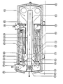
- the single figure shows a device for burning oxidizable constituents in a carrier gas such as exhaust gas, which can also be referred to as an afterburning device.
- the device comprises a cylindrical outer jacket 12 which is delimited by end walls 13 and 15.
- a burner 14 is arranged concentrically to the axis of the jacket 12, which is followed by a high-speed mixing tube 16 and a main combustion chamber 18, which is delimited by the outer end wall. It is not necessary that - as shown in the drawing - the high-speed mixing tube 16 protrudes into the main combustion chamber 18.
- An internal annular space 20 runs concentrically to the high-speed mixing tube 16, which in turn merges into a space 22 in which heat exchange / pre-combustion tubes 24 are arranged concentrically to the longitudinal axis of the device and thus to the high-speed mixing tube 16.
- the heat exchange / pre-combustion tubes 24 themselves open into an outer annular space 26 adjoining the outer wall 12, which in turn originates from an annular chamber 30 arranged concentrically with the burner 14, which in turn merges into the inlet opening 28.
- annular chamber 32 which adjoins the space 22 on the side opposite the annular chamber 30 and in an outlet opening Opening 34 opens.
- the ends 38 of the heat exchange / pre-combustion tubes 24 in the area of the outlet opening 34 are bent outwards, that is to say towards the wall 12, so as to pass almost perpendicularly into the wall 36 of the outer annular space 26.
- the other ends of the heat exchange / pre-combustion tubes 24 open into a tube plate 42 which shields a pre-combustion space 44 surrounding the burner 14 from the space 22.
- the burner 14 is surrounded by a burner stem 46, which usually widens conically in the direction of the high-speed tube 16. of the recesses on the peripheral surface. such as B. holes 48 has.
- the high-speed tube 16 is designed as a venturi nozzle 50 at the end facing the burner 14, an annular channel 54 being formed between the burner stem 46 and the outer end section 52 of the high-speed mixing tube 16, which is to be referred to as the flow cone.
- carrier gas is supplied to the outer annular space 26 via the inlet opening 28 of the adjoining annular chamber 30, from where the carrier gas is passed into the heat exchange / pre-combustion tubes 24.
- the gas first flows through the area in which the tubes 24 are bent outwards.
- the ends 38 are welded into the inner wall 36 of the outer annular space 26, and the distance between the ends 38 can be chosen to be relatively large, even in the case of a narrow heat exchanger tube packing, so that assembly is problem-free.
- the inner wall 36 in the area of the heat exchanger tube ends 38 can be chosen to be thin, which results in increased flexibility.
- the gas passes through the tube plate 42 into the pre-combustion chamber 44, in order then to be fed partly to the burner flame via the recesses 48 and partly to the high-speed mixing tube 16 via the annular gap 54.
- the gas After the gas is fed through the high-speed mixing tube 16 to the main combustion chamber 18, in which there is at the same time a strong swirling, the gas passes via the inner annular space 20 into the space 22 surrounding the heat exchanger / pre-combustion tubes 24, to the space 22 via the to wash the entire length in the cross-countercurrent, a multiple deflection (indicated by arrows) taking place within the space 22, so that heat exchange can take place to the required extent.
- the gas then passes through the annular chamber 32 to the outlet opening 34.
- the inner wall 36 of the outer annular space 26 is designed as a heat exchanger surface, along which the hot gases coming from the inner annular space 20 can flow, the gas supplied to the heat exchanger / preburning tubes 24 via the inlet opening 28 is preheated. This ensures that any condensate present evaporates, so that deposits in the heat exchanger / pre-combustion tubes 24 cannot occur. Since in the area of the bent ends 38 of the heat exchanger tubes 24 there is a temperature of only about 250 ° C. to 300 ° C., this temperature can be described as low in relation to the stress on the heat exchanger tubes, so that there is no risk of scale formation.
- bent ends 38 which serve to compensate for different linear expansions of the heat exchanger / pre-combustion tubes 24 due to temperature fluctuations and uneven flow.
- the low temperature of the gas in the area of the bent ends 38 also ensures that the flow velocity is so low that abrasion of the inner tube walls in the area of the bends is prevented by entrained particles.
- a "cold bypass" 53 can be provided between the chamber 30 and the pre-combustion chamber 44 without any problems in order to supply carrier gas containing cold, oxidizable components, in part directly to the burner 14 or to feed high-speed mixing tube 16. Since this area lies in the radiation area of the burner and the pre-combustion chamber - i.e. at a temperature between 600 ° C and 650 ° C - the risk of condensation deposits is completely excluded.
- a further advantage of the afterburning device according to the invention is that increased demands on the insulation of the outer wall 12 in the area of the outer annular space 26 are not to be made, since this forms a heat shield in that the cold carrier gas guided therein via the inner boundary wall 36 heat records.
- inlet and outlet openings 28 and 34 can be arranged separately from one another, there is also the possibility that the device can be mounted in a vertical construction. Structurally complex measures are not necessary for this, since external pipelines are not necessary for the functionality of the device.
Landscapes
- Engineering & Computer Science (AREA)
- Environmental & Geological Engineering (AREA)
- Mechanical Engineering (AREA)
- General Engineering & Computer Science (AREA)
- Heat-Exchange Devices With Radiators And Conduit Assemblies (AREA)
- Feeding And Controlling Fuel (AREA)
Description
- Die Erfindung bezieht sich auf eine Vorrichtung zum Verbrennen oxidierbarer Bestandteile in einem zu reinigenden Trägergas umfassend einen Gaseinlaß und einen Gasauslaß, einen Brenner mit sich anschließendem Hochgeschwindigkeitsmischraum, einen Brennraum sowie einen Wärmetauscher mit um den Hochgeschwindigkeitsmischraum herum angeordneten, vom zu reinigenden Gas im Kreuzgegenstrom zum gereinigten Gas durchströmten Rohren, die an einem Ende umgebogen sind.
- Eine entsprechende Vorrichtung ist der EP-A-0 040 690 zu entnehmen. Dabei sind die Wärmetauscherrohre an der heißen Seite der Vorrichtung, also im Bereich des Brenners nach innen umgebogen und in einer den Brenner konzentrisch umgebenden Trommel eingefügt. Zwar ergibt sich bei vielen prozeßabhängigen Einsätzen durch diese Konstruktion der Vorteil, daß temperaturbedingte unterschiedliche Ausdehnungen der einzelnen Rohre nicht zu Beschädigungen wie z. B. Rißbildungen führen. Allerdings bedarf es eines erheblichen herstellungstechnischen Aufwandes, um die nach innen umgebogenen Rohre mit der Trommel zu verschweißen, da die Abstände der Rohrenden klein sind. Die Trommel selbst kann einen Ausgleich für temperaturbedingte Wärmetauscher-Rohrausdehnungen nicht vornehmen, da eine relativ dicke Wandstärke erforderlich ist, damit die beim Verschweißen eingebrachte Schweißwärme nicht zu einer Schrumpfung und zu Verwerfungen der Trommel führt, wodurch andernfalls eine Verspannung der Rohrbogen erfolgen würde.
- Ferner nehmen die Wärmetauscherrohre nicht in ihrer gesamten Länge am Wärmetausch teil, da die abgebogenen Enden von den heißen Rauchgasen nicht direkt angeströmt werden, diese vielmehr durch einen Anströmraum so ab-und umgelenkt werden, daß sie nicht auf die abgebogenen Teilstücke der Rohre treffen. Ferner tritt Zunderbildung im Bereich der Rohrkrümmungen auf, da diese sich auf der heißesten Seite der Vorrichtung befinden. Zunderbildung kann jedoch zu einer Abzehrung der Rohrwanddicke führen, wenn die Rohre in diesem Bereich besonders hohe Dehn-Geschwindigkeitsänderungen erleiden. Solche besonderen Dehn-Geschwindigkeitsänderungen sind in der Regel prozeßbedingt.
- Aufgabe der vorliegenden Erfindung ist es, eine Vorrichtung der zuvor beschriebenen Art so auszubilden, daß mit konstruktiv einfachen Mitteln der Wärmetauscher gegen temperaturbedingte und schwankungsbedingte Ausdehnungen und Oberflächen-Schäden gesichert ist.
- Die Aufgabe wird erfindungsgemäß dadurch gelöst, daß die Wärmetauscherrohre an ihren kälteren Enden nach außen abgebogen sind. Hierdurch ergibt sich der Vorteil, daß die Rohrenden auf einer wesentlich größeren Umfangsfläche im Vergleich zu nach innen gebogenen Rohren angeordnet werden, so daß ein einfacheres Einschweißen und damit auch Automatentauglichkeit erreicht wird. Die eingeschweißten Enden können dabei einen erheblich größeren Abstand zueinander aufweisen, so daß der die Enden aufnehmende Mantel im Vergleich zum Stand der Technik kein extra Bauteil wie Trommel sein muß, vielmehr wird nach einer Ausgestaltung der Erfindung die innere Wandung eines äußeren Ringraumes als Befestigungsfläche benutzt, durch den das die oxidierbaren Bestandteile aufweisende Trägergas von der Eintrittsöffnung zu den Wärmetauscherrohren geführt wird. Da die Gefahr von Schrumpfungen und Verwerfungen beim Einschweißen der Rohre aufgrund des größeren Abstandes ausgeschlossen ist, kann das Wandmaterial dünner gewählt werden, so daß sich die Gesamtflexibilität des Kompensationsbereiches erhöht. Dadurch, daß für die nach außen umgebogenen Wärmetauscherrohrenden eine Fläche gewünschter Größe zur Verfügung gestellt werden kann, ergibt sich auch der Vorteil, daß die Zahl der übereinanderliegenden Rohrreihen bei zunehmender Rohrzahl an den äußeren Rohrreihen im Vergleich zu den Anordnungen nach der EP-A-0 040 690 erhöht werden kann, wodurch eine Steigerung der Turbulenz der Strömung um die Rohre erfolgt, so daß die Zahl der im Bereich des Wärmetauschers anzuordnenden Querstrom-Kammern verringert werden kann. Hierdurch ergeben sich konstruktive Vereinfachungen und Kostensenkungen.
- Ein weiterer großer Vorteil ist es, die Rohrwand dünner ausführen zu können, da keinerlei Zuschlag für Abzehrung durch Zunder-Flug gegeben werden muß. Durch den Wegfall des Wanddicken-Zuschlags aber erhöht sich wiederum die Gesamtflexibilität des Rohrbogens beträchtlich. Eine Kostensenkung stellt sich hierdurch ebenfalls ein. Auch wird der Einsatz niedrig legierter beziehungsweise unlegierter Rohre im Rundbogenbereich möglich.
- Auch besteht die Möglichkeit, die erfindungsgemäße Vorrichtung bei besonders kritischen Einsätzen zu verwenden, wo hohe Gas-Eintrittstemperaturen verbunden mit extremer Vorheizung bei Anwesenheit großer Mengen brennbarer Substanz zu stärkerem Vorabbrand von Teilen der brennbaren Stoffe führen. Es können dabei im Hochtemperatur-Abschnitt der Wärmetauscherrohre so hohe Temperaturen entstehen, die demnach von den nach außen geführten Kompensations-Rohrbögen ausgeglichen werden.
- Durch die erfindungsgemäße Vorrichtung kann daher ein Vorabbrand - stets mit höchster Vorheizung verbunden - nicht zu gravierenden Schädigungen führen. In diesem Sinne ist der Wärmeüberträger in seinem Hochtemperatur-Abschnitt bereits "Vorbrennkammer" und muß dieser Pflicht Rechnung tragen können.
- Ferner ist auch ein Vorteil der Erfindung darin zu sehen, daß der Hochtemperaturteil des Wärmetauschers verstärkt als eine erste Brennkammerstufe wirkt. Diese Eigenschaft tritt besonders bei kleiner Volumenstrom-Auslastung - verbunden mit hoher Belastung brennbarer Substanz - auf.
- Ermüdungsbruch-Gefahr ist schon allein dadurch beseitigt, daß die Kompensation mittels Rohrbogen im kalten Bereich angelegt wird, wo zulässige Spannungen um ein Vielfaches größer sind als im Bereich von z. B. 700° C.
- Von besonderem Vorteil ist, daß gefahrlos der Vorabbrand von Teilen der brennbaren Substanzen in den Röhren des Wärmetauschers erfolgen kann.
- Ein weiterer Vorteil in der Anordnung der umgebogenen Rohrenden auf der kalten Seite der Vorrichtung ist darin zu sehen, daß aufgrund der dort herrschenden niedrigen Strömungsgeschwindigkeit der innerhalb der Rohre strömenden Medien ein Abrieb im Rohrbogen nahezu ausgeschlossen ist.
- Im Grenzbereich zwischen laminarer und turbulenter Strömung sind einzelne Rohre oder Gruppen von Rohren laminarer beströmt (oder auch umströmt), während benachbarte Rohre oder Gruppen benachbarter Rohre Turbulent beströmt (oder auch umströmt) werden. Diese unerwünschte Eigenschaft ist nachteilig mit einem hohen Volumenstrom-Regelbereich der Verbrennungsvorrichtung verbunden. Die auch hieraus resultierenden, beträchtlichen Längendehnungs-Differenzen stellen ebenfalls hohe Anforderungen an die Elastizität der Einzelrohr-Kompensation. Erschwerend kommt hinzu, daß "Umschläge" von Laminarität nach Turbulenz und umgekehrt plötzlich auftreten. D. h. Dehnungs-Differenzen stellen sich mit großer Änderungsgeschwindigkeit ein. Auch und besonders dieser großen Änderungsgeschwindigkeit muß das Kompensationselement gewachsen sein. Ein Zunder behafteter Rohrbogen wäre das in weit geringerem Maße, weil er seinen Schutzzunder zu verlieren drohte.
- In Ausgestaltung der Erfindung ist das außerhalb der Wärmetauscherrohre strömende Gas über die Rohrbögen und die abgebogenen Rohrabschnitte zuführbar. Hierdurch sind die Rohrbögen in einem Temperaturbereich von in etwa 250°C - 300°C angeordnet, so daß die Gefahr einer Beschädigung durch hohe und schnelle Temperaturwechsel insgesamt oder auch zwischen Einzelrohren nahezu ausgeschlossen ist. Auch ist hier eine Zunderbildung ausgeschlossen, so daß eine Abzehrung unmöglich wird.
- Nach einer weiteren hervorzuhebenden Ausgestaltung der Erfindung wird das Trägergas von der Trägergaseinlaßöffnung über einen im Bereich der Außenwandung der im wesentlichen Zylinderform aufweisenden Vorrichtung verlaufenden äußeren Ringraum den umgebogenen Enden der Wärmetauscherrohre zugeführt. Dabei kann sich der Ringraum bis in die Auslaßöffnung hinein erstrecken. Hier wird u. a. der Vorteil erzielt, daß die Innenwandung des Ringraums und in schwächerem Maße auch die Außenwandung als Wärmetauscherfläche wirkt, so daß nicht nur ein Vorheizen der zugeführten Fluide erfolgt, sondern außerdem sichergestellt ist, daß vorhandene Kondensate bereits restlos vor Eintritt in die Wärmetauscherrohre verdampft sind. Auch ist zu erwähnen, daß die im Ringraum erfolgende Vorheizung den Aufwand am Rohr-Wärmetauscher mindert und dessen Kosten senkt.
- Dadurch, daß das kühle Trägergas mit oxidierbaren Bestandteilen in dem Außenmantel angrenzenden Ringraum zu den Wärmetauscherrohre geführt wird, bedarf es auch keiner aufwendigen äußeren Isolierung, und bei liegender Anordnung, keiner hochhitzefesten Fußkonstruktion.
- In Ausgestaltung der Erfindung erstreckt sich der Ringraum zwischen Trägergaseinlaß und Trägergasauslaßöffnung. Ferner zeichnet sich die Erfindung dadurch aus, daß die Trägergaseinlaßöffnung mit einer sich anschließenden ersten Ringkammer im Bereich des Brenners angeordnet ist, wobei die erste Ringkammer konzentrisch den Brenner umgibt.
- Die den Ansprüchen 1 und 3 zu entnehmenden Merkmale bieten in Kombination besonders hervorzuhebende Vorteile in z. B. der Vorerwärmung, der Kondensatverdampfung, der Längenkompensation, der gefahrlosen Vorverbrennung oder der Anordnung und der Befestigung der Wärmetauscherrohre.
- Die Erfindung wird nachstehend anhand eines der Zeichnung zu entnehmenden Ausführungsbeispiels näher erläutert.
- In der einzigen Figur ist eine Vorrichtung zum Verbrennen oxidierbarer Bestandteile in einem Trägergas wie Abgas dargestellt, die auch als Nachverbrennungsvorrichtung bezeichnet werden kann. Die Vorrichtung umfaßt einen zylinderförmigen Außenmantel 12, der durch Stirnwände 13 und 15 begrenzt ist. Im Bereich der Stirnwand 13 ist konzentrisch zur Achse des Mantels 12 ein Brenner 14 angeordnet, dem sich ein Hochgeschwindigkeits-Mischrohr 16 und ein Haupt-Brennraum 18, der durch die äußere Stirnwand begrenzt wird, anschließt. Dabei ist es nicht notwendigerweise erforderlich, daß - wie in der Zeichnung dargestellt - das Hochgeschwindigkeits-Mischrohr 16 In den Haupt-Brennraum 18 hineinragt. Konzentrisch zum Hochgeschwindigkeits-Mischrohr 16 verläuft ein innenliegender Ringraum 20, der seinerseits in einen Raum 22 übergeht, in dem Wärmetausch /Vorbrenn-Rohre 24 konzentrisch zur Längsachse der Vorrichtung und damit zum Hochgeschwindigkeits-Mischrohr 16 angeordnet sind. Die Wärmetausch/Vorbrenn-Rohre 24 selbst münden in einem äußeren, an die Außenwandung 12 angrenzenden äußeren Ringraum 26, der seinerseits von einer konzentrisch zum Brenner 14 angeordneten Ringkammer 30 ausgeht, die ihrerseits in die Einlaßöffnung 28 übergeht. Ferner ist eine Ringkammer 32 vorhanden, die sich auf der der Ringkammer 30 gegenüberliegenden Seite an den Raum 22 anschließt und in einer Auslaßöffnung 34 mündet.
- Die Enden 38 der Wärmetausch/Vorbrenn-Rohre 24 im Bereich der Auslaßöffnung 34 sind nach außen, also zur Wandung 12 hin umgebogen, um so nahezu senkrecht in die Wandung 36 des äußeren Ringraums 26 überzugehen. Die anderen Enden der Wärmetausch/Vorbrenn-Rohre 24 münden in einer Rohrplatte 42, die einen den Brenner 14 umgebenden Vorbrennraum 44 vom Raum 22 abschirmt.
- Der Brenner 14 ist von einem sich in Richtung des Hochgeschwindigkeitsrohres 16 meist kegelförmig erweiternden Brennervorbau 46 umgeben. der auf der Umfangsfläche Aussparungen. wie z. B. Löcher 48, aufweist. Das Hochgeschwindigkeitsrohr 16 ist an dem dem Brenner 14 zugewandten Ende als Venturi-Düse 50 ausgebildet, wobei sich zwischen dem Brennervorbau 46 und dem äußeren, als Anströmkonus zu bezeichnenden Endabschnitt 52 des Hochgeschwindigkeits Mischrohres 16 ein Ringkanal 54 ausbildet.
- Damit in der erfindungsgemäßen Vorrichtung in einem Trägergas vorhandene oxidierbare Bestandteile verbrennen können, wird dem äußeren Ringraum 26 Trägergas über die Einlaßöffnung 28 der sich anschließenden Ringkammer 30 zugeführt, von wo aus das Trägergas in die Wärmetausch/Vorbrenn-Rohre 24 geleitet wird. Dabei durchströmt das Gas zunächst den Bereich, in dem die Rohre 24 nach außen umgebogen sind. Hierzu sind die Enden 38 in die innere Wandung 36 des äußeren Ringraums 26 geschweißt, wobei auch bei einer engen Wärmetauscherrohrpackung der Abstand zwischen den Enden 38 relativ groß gewählt werden kann, so daß eine problemlose Montage erfolgt. Gleichzeitig kann die Innenwandung 36 im Bereich der Wärmetauscherrohrenden 38 dünn gewählt werden, wodurch sich eine erhöhte Flexibilität ergibt. Hierdurch können Längenänderungen der Wärmetauscherrohre 24 zusätzlich kompensiert werden. Von den Wärmetausch /Vorbrenn-Rohren gelangt das Gas durch die Rohrplatte 42 in den Vorbrennraum 44, um sodann teils über die Aussparungen 48 unmittelbar der Brennerflamme und teils über den Ringspalt 54 dem Hochgeschwindigkeits-Mischrohr 16 zugeführt zu werden. Nachdem das Gas durch das Hochgeschwindigkeits-Mischrohr 16 dem Haupt-Brennraum 18 zugeführt ist, in dem gleichzeitig eine starke Verwirbelung erfolgt, gelangt das Gas über den inneren Ringraum 20 in den die Wärmetauscher/Vorbrenn-Rohre 24 umgebenden Raum 22, um jene über die gesamte Länge im Quer-Gegenstrom zu umspülen, wobei innerhalb des Raumes 22 eine mehrfache Umlenkung (durch Pfeile angedeutet) erfolgt, damit im erforderlichen Umfang ein Wärmeaustausch erfolgen kann. Sodann gelangt das Gas über die Ringkammer 32 zur Auslaßöffnung 34.
- Dadurch, daß die Innenwandung 36 des äußeren Ringraums 26 als Wärmetauscherfläche ausgebildet ist, entlang der die von dem inneren Ringraum 20 kommenden heißen Gase strömen können, erfolgt eine Vorerwärmung des über die Eintrittsöffnung 28 den Wärmetauscher/Vorbrenn-Rohren 24 zugeführten Gases. Hierdurch ist gewährleistet, daß gegebenenfalls vorhandenes Kondensat verdampft, so daß Ablagerungen in den Wärmetauscher/Vorbrenn-Rohren 24 nicht erfolgen können. Da im Bereich der umgebogenen Enden 38 der Wärmetauscherrohre 24 eine Temperatur von lediglich etwa 250° C bis 300°C herrscht, ist diese Temperatur in bezug auf die Beanspruchung der Wärmetauscherrohre als niedrig zu bezeichnen, so daß die Gefahr einer Zunderbildung nicht gegeben ist. Hierdurch wird eine Abzehrung ausgeschlossen und durch die große Elastizität und hohe Festigkeit eine Ermüdung der umgebogenen Enden 38, die der Kompensation unterschiedlicher Längenausdehnungen der Wärmetauscher/Vorbrenn-Rohre 24 bedingt durch Temperaturschwankungen und ungleichen Strömung dienen, vermieden. Die niedrige Temperatur des Gases im Bereich der abgebogenen Enden 38 stellt außerdem sicher, daß die Strömungsgeschwindigkeit so gering ist, daß ein Abrieb der Rohrinnenwandungen im Bereich der Krümmungen durch mitgeführte Partikel unterbleibt.
- Da die Gaseinlaßöffnung 28 und die sich anschließende Ringkammer im heißen Teil der Vorrichtung angeordnet ist, kann problemlos ein "Kalt-Bypass" 53 zwischen der Kammer 30 und dem Vorbrennraum 44 vorgesehen werden, um kaltes, oxidierbare Bestandteile aufweisendes Trägergas zum Teil unmittelbar dem Brenner 14 bzw. Hochgeschwindigkeits-Mischrohr 16 zuzuführen. Da dieser Bereich im Strahlungsbereich des Brenners und des Vorbrennraums - also bei einer Temperatur zwischen 600°C und 650°C - liegt, ist die Gefahr von Kondensatablagerung völlig ausgeschlossen.
- Neben dem problemlosen Anordnen eines Kaltgas-Bypasses besteht auch die Möglichkeit, einen Heißgas-Bypass 51 zwischen der Haupt-Brennkammer 18 und der Auslaßöffnung 34 bzw. der in diese mündenden oberen Ringkammer 32 vorzusehen. Ansonsten ist jedoch eine erhöhte Wärmeisolierung zwischen der Haupt-Brennkammer 18 und der Ringkammer 32 vorgesehen, die ohne konstruktiven Aufwand erfolgen kann.
- Als weiterer Vorteil der erfindungsmäßigen Nachverbrennungsvorrichtung ist zu bezeichnen, daß erhöhte Anforderungen an die Isolation der Außenwandung 12 im Bereich des äußeren Ringraums 26 nicht zu stellen sind, da dieser eine Wärmeabschirmung dadurch bildet, daß das in diesem geführte kalte Trägergas über die innenliegende Begrenzungswand 36 Wärme aufnimmt.
- Dadurch, daß Einlaß- und Auslaßöffnungen 28 bzw. 34 getrennt voneinander angeordnet werden können, besteht außerdem die Möglichkeit, daß die Vorrichtung in vertikaler Bauweise montiert werden kann. Konstruktiv aufwendige Maßnahmen sind hierzu nicht erforderlich, da außenliegende Rohrleitungen für die Funktionstüchtigkeit der Vorrichtung nicht erforderlich sind.
Claims (7)
Priority Applications (1)
| Application Number | Priority Date | Filing Date | Title |
|---|---|---|---|
| AT86905767T ATE48029T1 (de) | 1985-09-10 | 1986-08-27 | Vorrichtung zum verbrennen oxidierbarer bestandteile in einem zu reinigenden traegergas. |
Applications Claiming Priority (2)
| Application Number | Priority Date | Filing Date | Title |
|---|---|---|---|
| DE19853532232 DE3532232A1 (de) | 1985-09-10 | 1985-09-10 | Vorrichtung zum verbrennen oxidierbarer bestandteile in einem traegergas |
| DE3532232 | 1985-09-10 |
Publications (2)
| Publication Number | Publication Date |
|---|---|
| EP0235277A1 EP0235277A1 (de) | 1987-09-09 |
| EP0235277B1 true EP0235277B1 (de) | 1989-11-15 |
Family
ID=6280547
Family Applications (1)
| Application Number | Title | Priority Date | Filing Date |
|---|---|---|---|
| EP86905767A Expired EP0235277B1 (de) | 1985-09-10 | 1986-08-27 | Vorrichtung zum verbrennen oxidierbarer bestandteile in einem zu reinigenden trägergas |
Country Status (6)
| Country | Link |
|---|---|
| US (1) | US4850857A (de) |
| EP (1) | EP0235277B1 (de) |
| AU (1) | AU597277B2 (de) |
| CA (1) | CA1276869C (de) |
| DE (2) | DE3532232A1 (de) |
| WO (1) | WO1987001434A1 (de) |
Cited By (1)
| Publication number | Priority date | Publication date | Assignee | Title |
|---|---|---|---|---|
| DE19608796C2 (de) * | 1996-03-07 | 2003-02-06 | Keu Gmbh | Verfahren und Vorrichtung zur thermischen Reinigung eines sauerstoffhaltigen Abgases |
Families Citing this family (52)
| Publication number | Priority date | Publication date | Assignee | Title |
|---|---|---|---|---|
| DE3605415A1 (de) * | 1986-02-20 | 1987-08-27 | Katec Betz Gmbh & Co | Verfahren und vorrichtung zum verbrennen oxidierbarer bestandteile in einem traegergas |
| DE3806114A1 (de) * | 1987-11-25 | 1989-06-08 | Man Technologie Gmbh | Thermisch isolierende erhitzer-gehaeuse-auskleidung und verbrennungsluftfuehrung fuer stirling- bzw. heissgasmotor |
| EP0326228A1 (de) * | 1988-01-29 | 1989-08-02 | Stork Contiweb B.V. | Heizungsvorrichtung |
| ATE89907T1 (de) * | 1990-03-10 | 1993-06-15 | Krantz H Gmbh & Co | Vorrichtung zum verbrennen von in einem abluftstrom enthaltenen oxidierbaren bestandteilen. |
| DE59004810D1 (de) * | 1990-03-10 | 1994-04-07 | Krantz H Gmbh & Co | Vorrichtung zum Verbrennen von Störstoffen. |
| US5306138A (en) * | 1992-03-10 | 1994-04-26 | Best Willie H | Method and apparatus for incinerating combustibles carried by an air stream |
| US5305608A (en) * | 1992-10-15 | 1994-04-26 | Hughes Aircraft Company | Liquid fuel power plant and method |
| DE4306417A1 (de) * | 1993-03-02 | 1994-09-08 | Grace Gmbh | Vorrichtung und Verfahren zum Verbrennen oxidierbarer Bestandteile in einem zu reinigenden Trägergas |
| US5427746A (en) * | 1994-03-08 | 1995-06-27 | W. R. Grace & Co.-Conn. | Flow modification devices for reducing emissions from thermal voc oxidizers |
| DE69527299D1 (de) * | 1994-10-27 | 2002-08-08 | Isentropic Sys Ltd | Verbesserungen in der verbrennung und in der verwendung von brenngasen |
| US5601789A (en) * | 1994-12-15 | 1997-02-11 | W. R. Grace & Co.-Conn. | Raw gas burner and process for burning oxygenic constituents in process gas |
| US5618173A (en) * | 1994-12-15 | 1997-04-08 | W.R. Grace & Co.-Conn. | Apparatus for burning oxygenic constituents in process gas |
| SE506894C2 (sv) * | 1995-12-04 | 1998-02-23 | Edmeston Ab | Rörvärmeväxlare med dubbelväggig mantel och förfarande och anläggning för tillverkning av kimrök |
| US5762880A (en) * | 1996-12-16 | 1998-06-09 | Megtec Systems, Inc. | Operational process and its improved control system of a secondary air burner |
| DE19848661B4 (de) * | 1998-10-22 | 2008-09-11 | Bayerische Motoren Werke Aktiengesellschaft | Thermische Nachverbrennungsanlage |
| US6435860B1 (en) * | 2000-04-28 | 2002-08-20 | Lfg & E International | Landfill condensate injection system |
| AT502684B1 (de) * | 2006-02-16 | 2007-05-15 | Freller Walter Ing | Vorrichtung zum verbrennen organischer stoffe |
| DE102007006268B3 (de) * | 2007-02-08 | 2008-05-29 | Probat-Werke Von Gimborn Maschinenfabrik Gmbh | Vorrichtung und Verfahren zur Wärmebehandlung eines schüttfähigen pflanzlichen Gutes |
| US8671658B2 (en) | 2007-10-23 | 2014-03-18 | Ener-Core Power, Inc. | Oxidizing fuel |
| US8393160B2 (en) | 2007-10-23 | 2013-03-12 | Flex Power Generation, Inc. | Managing leaks in a gas turbine system |
| US8701413B2 (en) | 2008-12-08 | 2014-04-22 | Ener-Core Power, Inc. | Oxidizing fuel in multiple operating modes |
| US8621869B2 (en) | 2009-05-01 | 2014-01-07 | Ener-Core Power, Inc. | Heating a reaction chamber |
| WO2011116010A1 (en) | 2010-03-15 | 2011-09-22 | Flexenergy, Inc. | Processing fuel and water |
| US9057028B2 (en) | 2011-05-25 | 2015-06-16 | Ener-Core Power, Inc. | Gasifier power plant and management of wastes |
| US9279364B2 (en) | 2011-11-04 | 2016-03-08 | Ener-Core Power, Inc. | Multi-combustor turbine |
| US9273606B2 (en) | 2011-11-04 | 2016-03-01 | Ener-Core Power, Inc. | Controls for multi-combustor turbine |
| US9381484B2 (en) | 2012-03-09 | 2016-07-05 | Ener-Core Power, Inc. | Gradual oxidation with adiabatic temperature above flameout temperature |
| US8671917B2 (en) | 2012-03-09 | 2014-03-18 | Ener-Core Power, Inc. | Gradual oxidation with reciprocating engine |
| US8980193B2 (en) | 2012-03-09 | 2015-03-17 | Ener-Core Power, Inc. | Gradual oxidation and multiple flow paths |
| US8926917B2 (en) | 2012-03-09 | 2015-01-06 | Ener-Core Power, Inc. | Gradual oxidation with adiabatic temperature above flameout temperature |
| US8844473B2 (en) | 2012-03-09 | 2014-09-30 | Ener-Core Power, Inc. | Gradual oxidation with reciprocating engine |
| US8980192B2 (en) | 2012-03-09 | 2015-03-17 | Ener-Core Power, Inc. | Gradual oxidation below flameout temperature |
| US9726374B2 (en) | 2012-03-09 | 2017-08-08 | Ener-Core Power, Inc. | Gradual oxidation with flue gas |
| US9347664B2 (en) | 2012-03-09 | 2016-05-24 | Ener-Core Power, Inc. | Gradual oxidation with heat control |
| US9353946B2 (en) | 2012-03-09 | 2016-05-31 | Ener-Core Power, Inc. | Gradual oxidation with heat transfer |
| US9234660B2 (en) | 2012-03-09 | 2016-01-12 | Ener-Core Power, Inc. | Gradual oxidation with heat transfer |
| US9567903B2 (en) | 2012-03-09 | 2017-02-14 | Ener-Core Power, Inc. | Gradual oxidation with heat transfer |
| US8807989B2 (en) | 2012-03-09 | 2014-08-19 | Ener-Core Power, Inc. | Staged gradual oxidation |
| US9273608B2 (en) | 2012-03-09 | 2016-03-01 | Ener-Core Power, Inc. | Gradual oxidation and autoignition temperature controls |
| US9206980B2 (en) | 2012-03-09 | 2015-12-08 | Ener-Core Power, Inc. | Gradual oxidation and autoignition temperature controls |
| US9359948B2 (en) | 2012-03-09 | 2016-06-07 | Ener-Core Power, Inc. | Gradual oxidation with heat control |
| US9359947B2 (en) | 2012-03-09 | 2016-06-07 | Ener-Core Power, Inc. | Gradual oxidation with heat control |
| US9371993B2 (en) | 2012-03-09 | 2016-06-21 | Ener-Core Power, Inc. | Gradual oxidation below flameout temperature |
| US9328660B2 (en) | 2012-03-09 | 2016-05-03 | Ener-Core Power, Inc. | Gradual oxidation and multiple flow paths |
| US9534780B2 (en) | 2012-03-09 | 2017-01-03 | Ener-Core Power, Inc. | Hybrid gradual oxidation |
| US9267432B2 (en) | 2012-03-09 | 2016-02-23 | Ener-Core Power, Inc. | Staged gradual oxidation |
| US9017618B2 (en) | 2012-03-09 | 2015-04-28 | Ener-Core Power, Inc. | Gradual oxidation with heat exchange media |
| US9328916B2 (en) | 2012-03-09 | 2016-05-03 | Ener-Core Power, Inc. | Gradual oxidation with heat control |
| DE102012102248B4 (de) * | 2012-03-16 | 2013-11-07 | Das Environmental Expert Gmbh | Vorrichtung zum Entsorgen von Schadgasen durch Verbrennen |
| DE102013203448A1 (de) * | 2013-02-28 | 2014-08-28 | Dürr Systems GmbH | Anlage und Verfahren zum Behandeln und/oder Verwerten von gasförmigemMedium |
| DE102014018178A1 (de) * | 2014-12-09 | 2016-06-09 | Eisenmann Se | Thermische Nachverbrennungsanlage |
| US9757690B2 (en) * | 2015-02-10 | 2017-09-12 | Noxtech, Inc. | Reactor apparatus and method for reducing NOx from exhaust gases produced by industrial processes |
Family Cites Families (14)
| Publication number | Priority date | Publication date | Assignee | Title |
|---|---|---|---|---|
| US1881206A (en) * | 1928-01-11 | 1932-10-04 | Superheater Co Ltd | Boiler |
| GB638298A (en) * | 1947-03-29 | 1950-06-07 | Power Jets Res & Dev Ltd | Improvements in or relating to heat exchangers |
| US3549333A (en) * | 1968-07-23 | 1970-12-22 | Universal Oil Prod Co | Recuperative form of direct thermal incinerator |
| GB1273200A (en) * | 1969-12-02 | 1972-05-03 | Universal Oil Prod Co | Thermal treatment unit for treating a contaminated gas stream |
| US3806322A (en) * | 1972-06-29 | 1974-04-23 | Universal Oil Prod Co | Recuperative form of catalytic-thermal incinerator |
| US3898040A (en) * | 1972-06-29 | 1975-08-05 | Universal Oil Prod Co | Recuperative form of thermal-catalytic incinerator |
| US3838975A (en) * | 1973-05-18 | 1974-10-01 | Universal Oil Prod Co | Thermal incinerator with heat recuperation |
| DE2352204B2 (de) * | 1973-10-18 | 1976-01-22 | Katec Katalytische Lufttechnik Betz & Co, 6461 Neuenhaßlau | Verbrennungseinrichtung zur verbrennung von stoerstoffen in abgasen |
| SE439980B (sv) * | 1978-06-02 | 1985-07-08 | United Stirling Ab & Co | Forfarande och anordning for reglering av luft/brensleblandning vid brennare av den typ som er utformade med ett evaporatorror |
| DE3014269C2 (de) * | 1980-04-14 | 1982-11-25 | Katec, Katalytische Lufttechnik Betz Gmbh & Co, 6467 Hasselroth | Verbrennungseinrichtung zur Verbrennung von Störstoffen in Abluft- und Abfallsubstanzen |
| DE3043286C2 (de) * | 1980-04-14 | 1982-06-16 | Katec, Katalytische Lufttechnik Betz Gmbh & Co, 6467 Hasselroth | Verbrennungseinrichtung zur Verbrennung von Störstoffen in Abgasen |
| US4365951A (en) * | 1980-06-13 | 1982-12-28 | Jan Alpkvist | Device for combustion of a volatile fuel with air |
| DE3107664C2 (de) * | 1981-02-28 | 1986-11-06 | Kraftanlagen Ag, 6900 Heidelberg | Einrichtung zur Nachverbrennung organischer Bestandteile in Proßesabgasen |
| DE3332070A1 (de) * | 1983-09-06 | 1985-03-28 | Wilhelm 8800 Ansbach Buschack | Heizautomat und abgasnachverbrennung |
-
1985
- 1985-09-10 DE DE19853532232 patent/DE3532232A1/de active Granted
-
1986
- 1986-08-27 EP EP86905767A patent/EP0235277B1/de not_active Expired
- 1986-08-27 US US06/948,345 patent/US4850857A/en not_active Expired - Lifetime
- 1986-08-27 WO PCT/EP1986/000501 patent/WO1987001434A1/de not_active Ceased
- 1986-08-27 AU AU63782/86A patent/AU597277B2/en not_active Ceased
- 1986-08-27 DE DE8686905767T patent/DE3666973D1/de not_active Expired
- 1986-08-28 CA CA000517066A patent/CA1276869C/en not_active Expired - Lifetime
Cited By (1)
| Publication number | Priority date | Publication date | Assignee | Title |
|---|---|---|---|---|
| DE19608796C2 (de) * | 1996-03-07 | 2003-02-06 | Keu Gmbh | Verfahren und Vorrichtung zur thermischen Reinigung eines sauerstoffhaltigen Abgases |
Also Published As
| Publication number | Publication date |
|---|---|
| WO1987001434A1 (fr) | 1987-03-12 |
| DE3532232A1 (de) | 1987-03-19 |
| DE3532232C2 (de) | 1987-11-26 |
| EP0235277A1 (de) | 1987-09-09 |
| US4850857A (en) | 1989-07-25 |
| AU6378286A (en) | 1987-03-24 |
| CA1276869C (en) | 1990-11-27 |
| DE3666973D1 (en) | 1989-12-21 |
| AU597277B2 (en) | 1990-05-31 |
Similar Documents
| Publication | Publication Date | Title |
|---|---|---|
| DE3532232C2 (de) | ||
| EP2881692B1 (de) | Gasturbinenkühlluftkühler, Gasturbinen- oder Gas- und Dampfturbinen- Kraftwerk sowie Verfahren zum Kühlen von Kühlluft | |
| EP0290812B1 (de) | Wärmetauscher, insbesondere zum Kühlen von Spaltgas | |
| DE2657529A1 (de) | Brenner fuer eine gasturbine | |
| DE2008311B2 (de) | Waermetauscher | |
| EP3159646B2 (de) | Wärmeübertrager | |
| DE7907706U1 (de) | Rauchgasdurchstroemter waermetauscher | |
| DE3043853C2 (de) | Heißgaskühler mit einem Druckbehälter | |
| EP0131187A2 (de) | Wärmetauscher zur Aufheizung von organischen Wärmeübertragungsmedien | |
| DE19833004A1 (de) | Wärmetauscher zum Kühlen eines heißen Prozeßgases | |
| DE2149536A1 (de) | Verfahren zum Erhitzen einer Waermeuebertragungsfluessigkeit | |
| EP2149636B1 (de) | Vorrichtung zum Aufheizen eines Wärmeträgers für insbesondere Wäschereimaschinen und bevorzugte Verwendungen der Vorrichtung | |
| DE3714671C2 (de) | ||
| DE2913748C2 (de) | Rohrbündelwärmetauscher zum Kühlen schlackenhaltiger Heißgase der Kohlevergasung | |
| DE202017107810U1 (de) | Druckfeste Brennerspitze | |
| EP0994322B1 (de) | Wärmetauscher mit einem Verbindungsstück | |
| DE3523610A1 (de) | Gekuehlter schirm als innenauskleidung fuer die reaktionsraeume von feuerungsanlagen | |
| EP0745805B1 (de) | Heizkessel | |
| EP0447631B1 (de) | Vorrichtung zum Verbrennen von Störstoffen | |
| DE2943590C2 (de) | ||
| DE874678C (de) | Roehrengaserhitzer, insbesondere fuer feste Brennstoffe, vorzugsweise zur Verwendungbei zweistufigen Gasturbinenanlagen | |
| EP0070371A1 (de) | Wärmeaustauscher | |
| DE3820494C2 (de) | Wärmetauscher | |
| DE2309696C3 (de) | Heizungskessel mit Umlenkkammer | |
| DE4208611A1 (de) | Atmosphärischer Gasbrenner mit einem schachtförmigen, einen Luftstrom führenden Gehäuse |
Legal Events
| Date | Code | Title | Description |
|---|---|---|---|
| PUAI | Public reference made under article 153(3) epc to a published international application that has entered the european phase |
Free format text: ORIGINAL CODE: 0009012 |
|
| AK | Designated contracting states |
Kind code of ref document: A1 Designated state(s): AT BE CH DE FR GB IT LI LU NL SE |
|
| 17P | Request for examination filed |
Effective date: 19870805 |
|
| 17Q | First examination report despatched |
Effective date: 19880421 |
|
| RAP1 | Party data changed (applicant data changed or rights of an application transferred) |
Owner name: GRACE GMBH |
|
| GRAA | (expected) grant |
Free format text: ORIGINAL CODE: 0009210 |
|
| AK | Designated contracting states |
Kind code of ref document: B1 Designated state(s): AT BE CH DE FR GB IT LI LU NL SE |
|
| REF | Corresponds to: |
Ref document number: 48029 Country of ref document: AT Date of ref document: 19891215 Kind code of ref document: T |
|
| REF | Corresponds to: |
Ref document number: 3666973 Country of ref document: DE Date of ref document: 19891221 |
|
| ITF | It: translation for a ep patent filed | ||
| ET | Fr: translation filed | ||
| GBT | Gb: translation of ep patent filed (gb section 77(6)(a)/1977) | ||
| PLBE | No opposition filed within time limit |
Free format text: ORIGINAL CODE: 0009261 |
|
| STAA | Information on the status of an ep patent application or granted ep patent |
Free format text: STATUS: NO OPPOSITION FILED WITHIN TIME LIMIT |
|
| 26N | No opposition filed | ||
| ITTA | It: last paid annual fee | ||
| EPTA | Lu: last paid annual fee | ||
| EAL | Se: european patent in force in sweden |
Ref document number: 86905767.9 |
|
| PGFP | Annual fee paid to national office [announced via postgrant information from national office to epo] |
Ref country code: LU Payment date: 19951001 Year of fee payment: 10 |
|
| PG25 | Lapsed in a contracting state [announced via postgrant information from national office to epo] |
Ref country code: LU Free format text: LAPSE BECAUSE OF NON-PAYMENT OF DUE FEES Effective date: 19960827 |
|
| REG | Reference to a national code |
Ref country code: CH Ref legal event code: PUE Owner name: GRACE GMBH TRANSFER- SEQUA GMBH & CO. MEGTEC SYSTE Ref country code: CH Ref legal event code: NV Representative=s name: R. A. EGLI & CO. PATENTANWAELTE |
|
| REG | Reference to a national code |
Ref country code: FR Ref legal event code: TP |
|
| REG | Reference to a national code |
Ref country code: GB Ref legal event code: 732E |
|
| NLS | Nl: assignments of ep-patents |
Owner name: SEQUA GMBH & CO. MEGTEC SYSTEMS KG |
|
| PGFP | Annual fee paid to national office [announced via postgrant information from national office to epo] |
Ref country code: SE Payment date: 19990804 Year of fee payment: 14 |
|
| PGFP | Annual fee paid to national office [announced via postgrant information from national office to epo] |
Ref country code: FR Payment date: 19990810 Year of fee payment: 14 |
|
| PGFP | Annual fee paid to national office [announced via postgrant information from national office to epo] |
Ref country code: AT Payment date: 19990812 Year of fee payment: 14 |
|
| PGFP | Annual fee paid to national office [announced via postgrant information from national office to epo] |
Ref country code: GB Payment date: 19990825 Year of fee payment: 14 |
|
| PGFP | Annual fee paid to national office [announced via postgrant information from national office to epo] |
Ref country code: CH Payment date: 19990930 Year of fee payment: 14 |
|
| PGFP | Annual fee paid to national office [announced via postgrant information from national office to epo] |
Ref country code: BE Payment date: 19991013 Year of fee payment: 14 |
|
| PG25 | Lapsed in a contracting state [announced via postgrant information from national office to epo] |
Ref country code: GB Free format text: LAPSE BECAUSE OF NON-PAYMENT OF DUE FEES Effective date: 20000827 Ref country code: AT Free format text: LAPSE BECAUSE OF NON-PAYMENT OF DUE FEES Effective date: 20000827 |
|
| PG25 | Lapsed in a contracting state [announced via postgrant information from national office to epo] |
Ref country code: SE Free format text: LAPSE BECAUSE OF NON-PAYMENT OF DUE FEES Effective date: 20000828 |
|
| PG25 | Lapsed in a contracting state [announced via postgrant information from national office to epo] |
Ref country code: LI Free format text: LAPSE BECAUSE OF NON-PAYMENT OF DUE FEES Effective date: 20000831 Ref country code: CH Free format text: LAPSE BECAUSE OF NON-PAYMENT OF DUE FEES Effective date: 20000831 Ref country code: BE Free format text: LAPSE BECAUSE OF NON-PAYMENT OF DUE FEES Effective date: 20000831 |
|
| BERE | Be: lapsed |
Owner name: SEQUA G.M.B.H. & CO. MEGTEC SYSTEMS K.G. Effective date: 20000831 |
|
| REG | Reference to a national code |
Ref country code: CH Ref legal event code: PL |
|
| GBPC | Gb: european patent ceased through non-payment of renewal fee |
Effective date: 20000827 |
|
| EUG | Se: european patent has lapsed |
Ref document number: 86905767.9 |
|
| PG25 | Lapsed in a contracting state [announced via postgrant information from national office to epo] |
Ref country code: FR Free format text: LAPSE BECAUSE OF NON-PAYMENT OF DUE FEES Effective date: 20010430 |
|
| REG | Reference to a national code |
Ref country code: FR Ref legal event code: ST |
|
| PGFP | Annual fee paid to national office [announced via postgrant information from national office to epo] |
Ref country code: NL Payment date: 20030831 Year of fee payment: 18 |
|
| PG25 | Lapsed in a contracting state [announced via postgrant information from national office to epo] |
Ref country code: NL Free format text: LAPSE BECAUSE OF NON-PAYMENT OF DUE FEES Effective date: 20050301 |
|
| NLV4 | Nl: lapsed or anulled due to non-payment of the annual fee |
Effective date: 20050301 |
|
| PGFP | Annual fee paid to national office [announced via postgrant information from national office to epo] |
Ref country code: DE Payment date: 20050825 Year of fee payment: 20 |
|
| PG25 | Lapsed in a contracting state [announced via postgrant information from national office to epo] |
Ref country code: IT Free format text: LAPSE BECAUSE OF NON-PAYMENT OF DUE FEES Effective date: 20050827 |