EP0234049B1 - Gummikissen-Presse - Google Patents
Gummikissen-Presse Download PDFInfo
- Publication number
- EP0234049B1 EP0234049B1 EP86118184A EP86118184A EP0234049B1 EP 0234049 B1 EP0234049 B1 EP 0234049B1 EP 86118184 A EP86118184 A EP 86118184A EP 86118184 A EP86118184 A EP 86118184A EP 0234049 B1 EP0234049 B1 EP 0234049B1
- Authority
- EP
- European Patent Office
- Prior art keywords
- piston
- rubber cushion
- press
- cylinder
- cylinder device
- Prior art date
- Legal status (The legal status is an assumption and is not a legal conclusion. Google has not performed a legal analysis and makes no representation as to the accuracy of the status listed.)
- Expired - Lifetime
Links
- 230000002093 peripheral effect Effects 0.000 claims description 2
- 230000007704 transition Effects 0.000 description 2
- 238000010276 construction Methods 0.000 description 1
Images
Classifications
-
- B—PERFORMING OPERATIONS; TRANSPORTING
- B21—MECHANICAL METAL-WORKING WITHOUT ESSENTIALLY REMOVING MATERIAL; PUNCHING METAL
- B21D—WORKING OR PROCESSING OF SHEET METAL OR METAL TUBES, RODS OR PROFILES WITHOUT ESSENTIALLY REMOVING MATERIAL; PUNCHING METAL
- B21D22/00—Shaping without cutting, by stamping, spinning, or deep-drawing
- B21D22/10—Stamping using yieldable or resilient pads
Definitions
- the invention relates generically to a rubber cushion press with upper spar, lower spar and working cylinder piston arrangement, the upper spar and lower spar being combined by means of tie rods to form a press frame, the lower spar furthermore carrying a table and a tool arranged thereon, and wherein in the upper spar a receiving case with device for the support of the inside of the case and the rubber cushion are arranged in this receiving case.
- the lower beam has the cylinder of the working cylinder piston arrangement.
- the piston guided in it carries the table with the tool.
- the storage case for the rubber cushion is located in the upper spar.
- the device for supporting the inside pressure of the case when working the rubber pillow press consists of a bandage which surrounds the upper spar in the area of the receiving case.
- the bandage forms an additional, mechanical component that has to be manufactured and assembled in a complex manner. It must also be designed for the highest working pressure of the rubber cushion press and does not automatically adjust to the stress to be absorbed and the deformation of the receiving case.
- a device for supporting the inside pressure of the case ensures that the upper spar in the area of the receiving case is not prematurely destroyed by overload.
- the invention has for its object to further develop a generic rubber cushion press so that a special bandage that surrounds the upper spar is no longer required for the inclusion of the case pressure and an adjustment of the support to the working pressure takes place by itself.
- the invention teaches that the upper spar has the cylinder of the working cylinder piston arrangement, in which the piston of the working cylinder piston arrangement can be moved up and down, that the receiving case is arranged in the piston or in a piston extension, and that the outer peripheral surface of the piston is opposite the upper spar forms an annular space which is acted upon by the pressure medium of the working cylinder piston arrangement for the support and forwarding of the case pressure.
- the piston of the working cylinder piston arrangement is expediently guided in the cylinder so that it cannot rotate.
- the rubber cushion must also be replaced from time to time in the case of the invention.
- the rubber cushion is otherwise covered by strips or the like.
- the pressure applied to the outside of the piston in the area of the receiving case can be adjusted with regard to its effective range, so that it can be adapted to different operating conditions.
- the invention teaches that the piston or the piston extension on the outer circumference has a height-adjustable seal on the tool side.
- a preferred embodiment of the invention which allows the inclusion of a relatively large rubber cushion, is characterized in that the piston together with the piston extension and correspondingly the cylinder space has a hat-shaped shape Have axial cross section, the receiving case is arranged in the region of the larger diameter, and that the annular space surrounds the region of the larger diameter and is continued via the transition between the region of the larger diameter and the smaller diameter.
- the invention uses the knowledge that in a rubber cushion press of the generic construction, the hydraulic pressure medium can perform an additional function, namely to support the inner pressure of the case if, as described, an annular space is provided and the pressure medium of the working cylinder piston arrangement when working the rubber cushion press is introduced into this annulus. This automatically adjusts to the working pressure.
- the inside pressure of the case is absorbed by the upper spar via the pressure medium. Due to the height adjustment of the seal, which surrounds the piston or the piston extension on the outer circumference on the tool side, it can be easily adapted to different operating conditions.
- the structure described also allows the piston to be provided with relatively thin piston walls in the area of the receiving case.
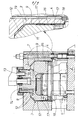
- the single figure shows a schematic representation of an axial section through a rubber cushion press.
- the rubber pillow press shown in the figure initially includes an upper beam 1, a lower beam 2 and a working cylinder piston arrangement 3.
- the upper beam 1 and the lower beam 2 are by means of Tie rod 4 combined into a press frame.
- the lower spar 2 carries a table 5 and a tool 6 arranged thereon.
- In the upper spar 1 there is a receiving case 7 with a device for supporting the inside pressure of the case.
- the rubber cushion 8 is arranged in this receiving case 7.
- the arrangement is such that the upper spar 1 has the cylinder 9 of the working cylinder piston arrangement 3, in which the piston 10 of the working cylinder piston arrangement 3 can be moved up and down.
- the receiving case 7 for the rubber cushion 8 is located in the piston 10 or in a piston extension 11.
- the outer circumferential surface of the receiving case 7 forms an annular space 12 with respect to the upper spar 1, which is acted upon by the pressure medium of the working cylinder piston arrangement 3 for supporting and transmitting the inside pressure of the case .
- the piston 10 of the working cylinder piston arrangement 3 is guided in the cylinder 9 in a rotationally fixed manner, for which purpose the pin 13 is provided.
- an ejection cylinder piston arrangement 14 for ejecting the rubber cushion 8 from the receiving case when the rubber cushion 8 has to be replaced. It is otherwise covered by strips 15.
- the piston 10 or the piston extension 11 has a seal 16 on the outer circumference on the tool side, which seals the annular space 12.
- This seal can be adjusted in height by insert parts 17 and is otherwise fixed by a retaining ring 18. By adjusting the height of the seal 16, it can be adapted to different operating conditions.
- the arrangement is such that the piston 10 together with the piston extension and accordingly the cylinder space have a hat-shaped axial cross section.
- the receiving case 7 is arranged in the region of the larger diameter D.
- the annular space 12 consequently also surrounds the region of the larger diameter D, but it extends over the transition 19 between the region of the larger diameter D and that of the smaller diameter d.
Landscapes
- Engineering & Computer Science (AREA)
- Mechanical Engineering (AREA)
- Presses And Accessory Devices Thereof (AREA)
- Press Drives And Press Lines (AREA)
- Shaping Metal By Deep-Drawing, Or The Like (AREA)
Description
- Die Erfindung bezieht sich gattungsgemäß auf eine Gummikissen-Presse mit Oberholm, Unterholm und Arbeitszylinderkolbenanordnung, wobei Oberholm und Unterholm mittels Zuganker zu einem Pressengestell vereinigt sind, wobei fernerhin der Unterholm einen Tisch sowie ein darauf angeordnetes Werkzeug trägt und wobei im Oberholm ein Aufnahmekoffer mit Einrichtung für die Abstützung des Kofferinnendrukkes und in diesem Aufnahmekoffer das Gummikissen angeordnet sind.
- Bei der bekannten Gummikissen-Presse (DE-A- 30 04 616) weist der Unterholm den Zylinder der Arbeitszylinderkolbenanordnung auf. Der darin geführte Kolben trägt den Tisch mit dem Werkzeug. Der Aufnahmekoffer für das Gummikissen befindet sich im Oberholm. Die Einrichtung für die Abstützung des Kofferinnendruckes beim Arbeiten der Gummikissen-Presse besteht aus einer Bandage, die den Oberholm im Bereich des Aufnahmekoffers umgibt. Die Bandage bildet ein zusätzliches, mechanisches Bauteil, welches aufwendig gefertigt und montiert werden muß. Es muß außerdem für den höchsten Arbeitsdruck der Gummikissen-Presse ausgelegt werden und stellt sich nicht von selbst auf die aufzunehmende Beanspruchung und die Verformung des Aufnahmekoffers ein. Andererseits stellt eine Einrichtung für die Abstützung des Kofferinnendruckes sicher, daß der Oberholm im Bereich des Aufnahmekoffers nicht durch Überlastung vorzeitig zerstört wird.
- Der Erfindung liegt die Aufgabe zugrunde, eine gattungsgemäße Gummikissen-Presse so weiter auszubilden, daß für die Aufnahme des Kofferinnendruckes eine besondere Bandage, die den Oberholm umgibt, nicht mehr erforderlich ist und von selbst eine Einstellung der Abstützung auf den Arbeitsdruck erfolgt.
- Zur Lösung dieser Aufgabe lehrt die Erfindung, daß der Oberholm den Zylinder der Arbeitszylinderkolbenanordning aufweist, in dem der Kolben der Arbeitszylinderkolbenanordnung aufundnieder bewegbar ist, daß in dem Kolben oder in einem Kolbenfortsatz der Aufnahmekoffer angeordnet ist, und daß die äußere Umfangsfläche des Kolbens gegenüber dem Oberholm einen Ringraum bildet, der für die Abstützung und Weiterleitung des Kofferinnendruckes von dem Druckmittel der Arbeitszylinderkolbenanordnung beaufschlagt ist. Der Kolben der Arbeitszylinderkolbenanordnung ist zweckmäßigerweise in dem Zylinder verdrehungsfest geführt.
- Wie bei allen Gummikissen-Pressen muß auch bei der erfindungsgemäßen das Gummikissen von Zeit zu Zeit ausgewechselt werden. Das ist auf besonders einfache Weise möglich, weil man in dem Kolben zumindest eine Ausstoßzylinderkolbenanordnung zum Ausstoßen des Gummikissens aus dem Koffer zusätzlich anordnen kann. Es versteht sich, daß das Gummikissen im übrigen durch Leisten oder dergleichen unterfaßt ist. Die Druckbeaufschlagung, die der Kolben im Bereich des Aufnahmekoffers außenseitig erfährt, kann bezüglich ihres Wirkungsbereiches eingestellt werden, so daß eine Anpassung an unterschiedliche Betriebsverhältnisse möglich ist. Dazu lehrt die Erfindung, daß der Kolben bzw. der Kolbenfortsatz am Außenumfang werkzeugseitig eine höhenverstellbare Dichtung aufweist.
- Die Gestaltung des Kolbens ist im Rahmen der Erfindung grundsätzlich beliebig. Eine bevorzugte Ausführungsform der Erfindung, die die Aufnahme eines verhältnismäßig großen Gummikissens ermöglicht, ist dadurch gekennzeichnet, daß der Kolben zusammen mit dem Kolbenfortsatz und entsprechend der Zylinderraum einen hutförmigen Axialquerschnitt aufweisen, wobei im Bereich des größeren Durchmessers der Aufnahmekoffer angeordnet ist, und daß der Ringraum den Bereich des größeren Durchmessers umgibt sowie über den Übergang zwischen den Bereich des größeren Durchmessers und des kleineren Durchmessers fortgeführt ist.
- Die Erfindung nutzt die Erkenntnis, daß bei einer Gummikissen-Presse des gattungsgemäßen Aufbaus das hydraulische Druckmittel eine zusätzlich Funktion erfüllen kann, nämlich zur Abstützung des Kofferinnendruckes beitragen kann, wenn, wie beschrieben ein Ringraum vorgesehen und das Druckmittel der Arbeitszylinderkolbenanordnung beim Arbeiten der Gummikissen-Presse in diesen Ringraum eingeführt wird. Dabei erfolgt von selbst eine Anpassung an den Arbeitsdruck. Der Kofferinnendruck wird im übrigen über das Druckmittel von dem Oberholm aufgenommen. Durch die Höhenverstellung der Dichtung, die den Kolben bzw. den Kolbenfortsatz am Außenumfang werkzeugseitig umgibt, kann auf einfache Weise eine Anpassung an unterschiedliche Betriebsverhältnisse erfolgen. Der beschriebene Aufbau erlaubt es im übrigen, den Kolben im Bereich des Aufnahmekoffers mit verhältnismäßig dünnen Kolbenwandungen zu versehen.
- Im folgenden wird die Erfindung anhand einer lediglich ein Ausführungsbeispiel darstellenden Zeichnung ausführlicher erläutert.
- Die einzige Figur zeigt in schematischer Darstellung einen Axialschnitt durch eine Gummikissen-Presse.
- Zu der in der Figure dargestellten Gummikissen-Presse gehören zunächst ein Oberholm 1, ein Unterholm 2 und eine Arbeitszylinderkolbenanordnung 3. Der Oberholm 1 und der Unterholm 2 sind mittels Zuganker 4 zu einem Pressengestell vereinigt. Der Unterholm 2 trägt einen Tisch 5 sowie ein darauf angeordnetes Werkzeug 6. Im Oberholm 1 befindet sich ein Aufnahmekoffer 7 mit Einrichtung für die Abstützung des Kofferinnendruckes. In diesem Aufnahmekoffer 7 ist das Gummikissen 8 angeordnet.
- Die Anordnung ist so getroffen, daß der Oberholm 1 den Zylinder 9 der Arbeitszylinderkolbenanordnung 3 aufweist, in dem der Kolben 10 der Arbeitszylinderkolbenanordnung 3 aufundnieder bewegbar ist. In dem Kolben 10 oder in einem Kolbenfortsatz 11 befindet sich der Aufnahmekoffer 7 für das Gummikissen 8. Die äußere Umfangsfläche des Aufnahmekoffers 7 bildet gegenüber dem Oberholm 1 einen Ringraum 12, der für die Abstützung und Weiterleitung des Kofferinnendruckes von dem Druckmittel der Arbeitszylinderkolbenanordnung 3 beaufschlagt ist. Der Kolben 10 der Arbeitszylinderkolbenanordnung 3 ist in dem Zylinder 9 verdrehungsfest geführt, wozu der Bolzen 13 vorgesehen ist. In dem Kolben 10 befindet sich im übrigen eine Ausstoßzylinderkolbenanordnung 14 zum Ausstoßen des Gummikissens 8 aus dem Aufnahmekoffer, wenn das Gummikissen 8 ausgewechselt werden muß. Es ist im übrigen von Leisten 15 unterfaßt.
- Der Kolben 10 bzw. der Kolbenfortsatz 11 besitzt am Außenumfang werkzeugseitig eine Dichtung 16, die den Ringraum 12 abdichtet. Diese Dichtung ist durch Beilageteile 17 höhenverstellbar und wird im übrigen durch einen Haltering 18 fixiert. Indem die Dichtung 16 höhenverstellt wird, kann eine Anpassung an unterschiedliche Betriebsverhältnisse erfolgen.
- Im Ausführungsbeispiel ist die Anordnung so getroffen, daß der Kolben 10 zusammen mit dem Kolbenfortsatz und entsprechend der Zylinderraum einen hutförmigen Axialquerschnitt aufweisen. Im Bereich des größeren Durchmessers D ist der Aufnahmekoffer 7 angeordnet. Der Ringraum 12 umgibt folglich ebenfalls den Bereich des größeren Durchmessers D, er erstreckt sich aber über den Übergang 19 zwischen dem Bereich des größeren Durchmessers D und dem des Kleineren Durchmessers d.
Claims (5)
- Gummikissen-Presse mit Oberholm (1), Unterholm (2) und Arbeitszylinderkolbenanordnung (3), wobei Oberholm (1) und Unterholm (2) mittels Zuganker (4) zu einem Pressengestell vereinigt sind, wobei fernerhin der Unterholm einen Tisch (5) sowie ein darauf angeordnetes Werkzeug (6) trägt und wobei im Oberholm (11) ein Aufnahmekoffer (7) mit Einrichtung für die Abstützung des Kofferinnendruckes und in diesem Aufnahmekoffer (7) das Gummikissen (8) angeordnet sind, dadurch gekennzeichnet, daß der Oberholm (1) den Zylinder (9) der Arbeitszylinderkolbenanordnung (3) aufweist, in dem der Kolben (10) der Arbeitszylinderkolbenanordnung (3) aufundnieder bewegbar ist, daß in dem Kolben (10) oder in einem Kolbenfortsatz (11) der Aufnahmekoffer (7) angeordnet ist, und daß die äußere Umfangsfläche des Kolbens (10) gegenüber dem Oberholm (1) einen Ringraum (12) bildet, der für die Abstützung und Weiterleitung des Kofferinnendruckes von dem Druckmittel der Arbeitszylinderkolbenanordnung (3) beaufschlagt ist.
- Gummikisen-Presse nach Anspruch 1, dadurch gekennzeichnet, daß der Kolben (10) der Arbeitszylinderkolbenanordnung (3) in dem Zylinder (9) verdrehungsfest geführt ist.
- Gummikissen-Presse nach einem der Ansprüche 1 oder 2, dadurch gekennzeichnet, daß in dem Kolben (10) zumindest eine Ausstoßzylinderkolbenanordnung (14) zum Ausstoßen des Gummikissens (8) aus dem Aufnahmekoffer (7) angeordnet ist.
- Gummikissen-Presse nach einem der Ansprüche 1 bis 3, dadurch gekennzeichnet, daß der Kolben (10) bzw. der Kolbenfortsatz (11) am Außenumfang werkzeugseitig eine höhenverstellbare Dichtung (16) aufweist.
- Gummikissen-Presse nach einem der Ansprüche 1 bis 4, dadurch gekennzeichnet, daß der Kolben (10) mit dem Kolbenfortsatz (11) und entsprechend der Zylinderraum einen hutförmigen Axialquerschnitt aufweisen, wobei im Bereich des größeren Durchmessers (D) der Aufnahmekoffer (7) angeordnet ist, und daß der Ringraum (12) den Bereich des größeren Durchmessers (D) umgibt sowie über den Übergang (19) zwischen dem Bereich des größeren Durchmessers (D) und dem Bereich des kleineren Durchmessers (d) fortgeführt ist.
Applications Claiming Priority (2)
| Application Number | Priority Date | Filing Date | Title |
|---|---|---|---|
| DE19863605728 DE3605728A1 (de) | 1986-02-22 | 1986-02-22 | Gummikissen-presse |
| DE3605728 | 1986-02-22 |
Publications (3)
| Publication Number | Publication Date |
|---|---|
| EP0234049A2 EP0234049A2 (de) | 1987-09-02 |
| EP0234049A3 EP0234049A3 (en) | 1989-02-08 |
| EP0234049B1 true EP0234049B1 (de) | 1991-03-27 |
Family
ID=6294704
Family Applications (1)
| Application Number | Title | Priority Date | Filing Date |
|---|---|---|---|
| EP86118184A Expired - Lifetime EP0234049B1 (de) | 1986-02-22 | 1986-12-31 | Gummikissen-Presse |
Country Status (4)
| Country | Link |
|---|---|
| US (1) | US4829807A (de) |
| EP (1) | EP0234049B1 (de) |
| JP (1) | JPS62296996A (de) |
| DE (1) | DE3605728A1 (de) |
Families Citing this family (3)
| Publication number | Priority date | Publication date | Assignee | Title |
|---|---|---|---|---|
| US5501600A (en) * | 1994-09-22 | 1996-03-26 | Johnson; Paul W. | Method of laminating a porcelain veneer to a tooth |
| US6233989B1 (en) | 2000-10-13 | 2001-05-22 | Changing Paradigms, Llc | Method and apparatus for stamping a metal sheet with an apertured design having rolled edges |
| EP4387785A4 (de) * | 2021-12-06 | 2024-12-18 | Coskunöz Kalip Makina Sanayi ve Ticaret Anonim Sirketi | Formausführung |
Family Cites Families (14)
| Publication number | Priority date | Publication date | Assignee | Title |
|---|---|---|---|---|
| DE93318C (de) * | ||||
| FR875339A (fr) * | 1939-10-13 | 1942-09-16 | Focke Wulf Flugzeugbau Gmbh | Dispositif pour l'emboutissage de pièces de tôle |
| US2840025A (en) * | 1953-08-04 | 1958-06-24 | Baldwin Lima Hamilton Corp | Mounting for resilient press pads of polygonal cross-section |
| US2966873A (en) * | 1955-01-11 | 1961-01-03 | Lockheed Aircraft Corp | Device for forming sheet material |
| US3120205A (en) * | 1956-02-07 | 1964-02-04 | Gen Tire & Rubber Co | Forming pad for hydraulic press |
| US3224042A (en) * | 1963-10-23 | 1965-12-21 | Barogenics Inc | Hydrostatic pressure device |
| US3490344A (en) * | 1967-07-10 | 1970-01-20 | Western Electric Co | Pressure vessel |
| US3681958A (en) * | 1970-10-15 | 1972-08-08 | Grumman Aerospace Corp | High pressure forming press |
| SE391483B (sv) * | 1975-06-24 | 1977-02-21 | Asea Ab | Press med expanderbar tryckcell och formdyna |
| SE408383B (sv) * | 1976-04-08 | 1979-06-11 | Asea Ab | Press for formning av platar och dylikt med hjelp av en formdyna, som under formningsskedet er innesluten i en kavitet, som bildas av en ovre och en undre verktygsdel av vilka minst en er rorligt anordnad i ett ... |
| DE2655605C2 (de) * | 1976-12-08 | 1978-10-05 | G. Siempelkamp Gmbh & Co, 4150 Krefeld | Gummikissen-Ziehpresse |
| US4162625A (en) * | 1978-01-24 | 1979-07-31 | Simmons David E | Method and apparatus for forming dental copings |
| DE3004616C2 (de) * | 1980-02-08 | 1982-11-04 | Becker & van Hüllen Niederrheinische Maschinenfabrik GmbH & Co, 4150 Krefeld | Gummikissen-Ziehpresse |
| DE3145121A1 (de) * | 1981-11-13 | 1983-05-26 | G. Siempelkamp Gmbh & Co, 4150 Krefeld | Hydraulische presse mit auswechselbarem gummikissen |
-
1986
- 1986-02-22 DE DE19863605728 patent/DE3605728A1/de active Granted
- 1986-12-31 EP EP86118184A patent/EP0234049B1/de not_active Expired - Lifetime
-
1987
- 1987-02-20 JP JP62036005A patent/JPS62296996A/ja active Granted
-
1988
- 1988-07-25 US US07/223,560 patent/US4829807A/en not_active Expired - Fee Related
Also Published As
| Publication number | Publication date |
|---|---|
| US4829807A (en) | 1989-05-16 |
| DE3605728C2 (de) | 1988-11-17 |
| JPH0249837B2 (de) | 1990-10-31 |
| EP0234049A3 (en) | 1989-02-08 |
| EP0234049A2 (de) | 1987-09-02 |
| JPS62296996A (ja) | 1987-12-24 |
| DE3605728A1 (de) | 1987-08-27 |
Similar Documents
| Publication | Publication Date | Title |
|---|---|---|
| DE2302732A1 (de) | Einstellbare daempfungsvorrichtung | |
| DE3145655C1 (de) | Schuesselmuehlengetriebe | |
| DE2411340A1 (de) | Schmiedepresse | |
| DE69803904T2 (de) | Antriebsvorrichtung | |
| EP1952975B1 (de) | Pulverpresse zur Herstellung von Presslingen aus Metallpulver | |
| EP0260546B1 (de) | Schmiedemaschine | |
| EP0343347A1 (de) | Werkzeugrevolver | |
| DE3443716A1 (de) | Walzenschuesselmuehle | |
| EP0396904B1 (de) | Vorrichtung zum Anstellen und Abheben eines auf einen Formzylinder wirkenden Gegendruckzylinders | |
| DE2500859B2 (de) | Hydraulisches Kletterhubwerk | |
| DE2424783A1 (de) | Vorrichtung zum veraendern des abstandes zwischen tisch und stoessel an der stoesselgarnitur einer presse | |
| DE3008049A1 (de) | Vorrichtung zur stossdaempfung an einer presse | |
| DE3605728C2 (de) | ||
| DE2108326B2 (de) | Walzenpresse | |
| DE2734550C3 (de) | Vorrichtung zum Heben und Abstützen eines Bauwerks | |
| DE2229073C2 (de) | Vorrichtung zum gleichzeitigen Spannen mehrerer Schraubenbolzen, Dehnschrauben, Zuganker oder dergleichen | |
| DE2450973A1 (de) | Vorrichtung zur vollautomatischen hubverstellung bei doppelstaenderpressen mit zweipunktantrieb in sogenannter querwellenausfuehrung | |
| EP0609748A1 (de) | Bewegungsantrieb zur translatorischen Bewegung von Bauteilen | |
| EP3072675A1 (de) | Rundlaufpresse mit mindestens einer auf einer Trägerplatte befestigbaren Druckrollenstation sowie Verfahren zum Befestigen und Lösen der Druckrollenstation | |
| DE2506000C3 (de) | Einbauteil bei einem Tiefofenkran, Stripperkran oder einem Universalstripperkran | |
| DE19636424A1 (de) | Vorrichtung zur Herstellung von Konturen in der Wandung eines Hohlprofiles | |
| DE1126325B (de) | Sicherheitseinrichtung gegen UEberlastung eines Spindelantriebes fuer grosse Hubkoerper, insbesondere Schiffshebewerke | |
| DE2300581A1 (de) | Siebdruckmaschine | |
| DE963845C (de) | Einstaender-Schleifmaschine | |
| DE2225162C3 (de) | Getriebe mit veränderbarer Übersetzung, insbes, für elektrische Lokomotiven |
Legal Events
| Date | Code | Title | Description |
|---|---|---|---|
| PUAI | Public reference made under article 153(3) epc to a published international application that has entered the european phase |
Free format text: ORIGINAL CODE: 0009012 |
|
| 17P | Request for examination filed |
Effective date: 19870212 |
|
| AK | Designated contracting states |
Kind code of ref document: A2 Designated state(s): ES FR GB IT SE |
|
| PUAL | Search report despatched |
Free format text: ORIGINAL CODE: 0009013 |
|
| AK | Designated contracting states |
Kind code of ref document: A3 Designated state(s): ES FR GB IT SE |
|
| RAP1 | Party data changed (applicant data changed or rights of an application transferred) |
Owner name: SIEMPELKAMP PRESSEN SYSTEME GMBH & CO. |
|
| 17Q | First examination report despatched |
Effective date: 19900822 |
|
| GRAA | (expected) grant |
Free format text: ORIGINAL CODE: 0009210 |
|
| AK | Designated contracting states |
Kind code of ref document: B1 Designated state(s): ES FR GB IT SE |
|
| PG25 | Lapsed in a contracting state [announced via postgrant information from national office to epo] |
Ref country code: IT Free format text: LAPSE BECAUSE OF FAILURE TO SUBMIT A TRANSLATION OF THE DESCRIPTION OR TO PAY THE FEE WITHIN THE PRE;WARNING: LAPSES OF ITALIAN PATENTS WITH EFFECTIVE DATE BEFORE 2007 MAY HAVE OCCURRED AT ANY TIME BEFORE 2007. THE CORRECT EFFECTIVE DATE MAY BE DIFFERENT FROM THE ONE RECORDED.SCRIBED TIME-LIMIT Effective date: 19910327 Ref country code: SE Effective date: 19910327 |
|
| GBT | Gb: translation of ep patent filed (gb section 77(6)(a)/1977) | ||
| ET | Fr: translation filed | ||
| PG25 | Lapsed in a contracting state [announced via postgrant information from national office to epo] |
Ref country code: ES Free format text: LAPSE BECAUSE OF FAILURE TO SUBMIT A TRANSLATION OF THE DESCRIPTION OR TO PAY THE FEE WITHIN THE PRESCRIBED TIME-LIMIT Effective date: 19910708 |
|
| K2C3 | Correction of patent specification (complete document) published |
Effective date: 19910327 |
|
| PLBE | No opposition filed within time limit |
Free format text: ORIGINAL CODE: 0009261 |
|
| STAA | Information on the status of an ep patent application or granted ep patent |
Free format text: STATUS: NO OPPOSITION FILED WITHIN TIME LIMIT |
|
| 26N | No opposition filed | ||
| PGFP | Annual fee paid to national office [announced via postgrant information from national office to epo] |
Ref country code: GB Payment date: 19921001 Year of fee payment: 7 |
|
| PG25 | Lapsed in a contracting state [announced via postgrant information from national office to epo] |
Ref country code: GB Effective date: 19931231 |
|
| GBPC | Gb: european patent ceased through non-payment of renewal fee |
Effective date: 19931231 |
|
| PGFP | Annual fee paid to national office [announced via postgrant information from national office to epo] |
Ref country code: FR Payment date: 19941208 Year of fee payment: 9 |
|
| PG25 | Lapsed in a contracting state [announced via postgrant information from national office to epo] |
Ref country code: FR Effective date: 19960830 |
|
| REG | Reference to a national code |
Ref country code: FR Ref legal event code: ST |