EP0229933B1 - Wirbelströmungsmesser - Google Patents
Wirbelströmungsmesser Download PDFInfo
- Publication number
- EP0229933B1 EP0229933B1 EP86116478A EP86116478A EP0229933B1 EP 0229933 B1 EP0229933 B1 EP 0229933B1 EP 86116478 A EP86116478 A EP 86116478A EP 86116478 A EP86116478 A EP 86116478A EP 0229933 B1 EP0229933 B1 EP 0229933B1
- Authority
- EP
- European Patent Office
- Prior art keywords
- capacitance
- vortex
- sensor
- pressure fluctuations
- measuring
- Prior art date
- Legal status (The legal status is an assumption and is not a legal conclusion. Google has not performed a legal analysis and makes no representation as to the accuracy of the status listed.)
- Expired - Lifetime
Links
Images
Classifications
-
- G—PHYSICS
- G01—MEASURING; TESTING
- G01P—MEASURING LINEAR OR ANGULAR SPEED, ACCELERATION, DECELERATION, OR SHOCK; INDICATING PRESENCE, ABSENCE, OR DIRECTION, OF MOVEMENT
- G01P5/00—Measuring speed of fluids, e.g. of air stream; Measuring speed of bodies relative to fluids, e.g. of ship, of aircraft
- G01P5/01—Measuring speed of fluids, e.g. of air stream; Measuring speed of bodies relative to fluids, e.g. of ship, of aircraft by using swirlflowmeter
-
- G—PHYSICS
- G01—MEASURING; TESTING
- G01F—MEASURING VOLUME, VOLUME FLOW, MASS FLOW OR LIQUID LEVEL; METERING BY VOLUME
- G01F1/00—Measuring the volume flow or mass flow of fluid or fluent solid material wherein the fluid passes through a meter in a continuous flow
- G01F1/05—Measuring the volume flow or mass flow of fluid or fluent solid material wherein the fluid passes through a meter in a continuous flow by using mechanical effects
- G01F1/20—Measuring the volume flow or mass flow of fluid or fluent solid material wherein the fluid passes through a meter in a continuous flow by using mechanical effects by detection of dynamic effects of the flow
- G01F1/32—Measuring the volume flow or mass flow of fluid or fluent solid material wherein the fluid passes through a meter in a continuous flow by using mechanical effects by detection of dynamic effects of the flow using swirl flowmeters
- G01F1/325—Means for detecting quantities used as proxy variables for swirl
- G01F1/3259—Means for detecting quantities used as proxy variables for swirl for detecting fluid pressure oscillations
Definitions
- the invention relates to a vortex flow meter for measuring the rate of disturbance of a flow medium in a pipeline, with a bluff body arranged in the flow channel of the pipeline, which is designed to generate Kármán vortices, a vortex sensor which acts on the pressure fluctuations generated by the Kármán vortices responds, wherein the vortex sensor has a first oscillating body, which can be deflected by the vortex pressure fluctuations, and a capacitive transducer with an electrode holder, which is arranged in a cavity of the first oscillating body which is sealed off from the flow medium and carries at least one capacitor electrode which corresponds to an electrode section of the lies opposite the first vibrating body in such a way that it forms a measuring capacity with it, which is caused by a deflection of the first one caused by the vortex pressure fluctuations Vibrating body is variable, the electrode holder being designed as a second vibrating body, which is decoupled from the swirl pressure fluctuations, and with an evaluation circuit which contains a
- the bluff body itself forms the first vibrating body of the vortex sensor.
- the bluff body therefore contains a cavity which is sealed off from the flow medium and in which the electrode holder of the capacitive transducer is arranged.
- the bluff body is extended by an approach to more than twice the diameter of the flow channel and supported at both ends so that it is caused by the vortex pressure fluctuations in bending vibrations.
- the oscillating movement of the bluff body relative to the electrode holder fixed in its cavity results in changes in capacitance between the electrodes carried by the electrode holder and the wall sections of the bluff body cavity opposite these electrodes.
- the electrode holder is rod-shaped and clamped at one end, so that it forms a second oscillating body which, under the influence of external forces, can also be set into bending vibrations by which its free end carrying the electrodes is deflected.
- the aim is to ensure that the deflections of these two vibrating bodies at the height of the electrodes are approximately the same size and the same direction under the influence of vibrations or similar interfering influences, so that such deflections do not occur Result in changes in capacity.
- this condition can only be met with difficulty and incompletely, because in particular the formation of the first vibrating body is predominantly determined by its function as a bluff body.
- the vibration amplitudes that can be achieved by the swirl pressure fluctuations and consequently the changes in capacitance caused thereby are relatively small, which affects the sensitivity of the swirl sensor.
- the vibration behavior of the electrode holder cannot be adapted well to the vibration behavior of the bluff body, so that the compensation of vibrations and similar disturbances is only possible in an imperfect manner. It is also often undesirable, especially with larger nominal widths of the flow channel, for the bluff body to vibrate itself.
- a second piezoelectric transducer of the same type is arranged outside the pipeline in such a way that it responds only to the vibrations and interferences, but not to the deflections of the pressure-receiving plate. This results in a considerable length of the swirl sensor, a large part of which is outside the pipeline.
- the capacitance measuring circuit of the vortex flow meter described in US-A-4 362 061 contains a bridge circuit which contains the two capacitances in two bridge branches which are formed by two pairs of electrodes arranged on opposite sides of the two oscillating bodies. An AC voltage is applied to one bridge diagonal, so that an AC voltage is obtained on the other bridge diagonal, which depends on the difference between the two capacitances. Since the two capacitances change in opposite directions as a result of the oscillating movements of the two oscillating bodies, the bridge output AC voltage is amplitude-modulated with the frequency of the swirl pressure fluctuations.
- This capacitance measuring circuit contains a switching arrangement for each measuring capacitance, which applies the measuring capacitance with a predetermined switching frequency periodically alternately for charging to a constant voltage and connects for discharging with a storage capacitor, the capacitance of which is large compared to the measuring capacitance and the terminal voltage of which is essentially due to a controlled discharge current is kept at a constant reference potential.
- the capacitance measurement is based on the measurement of the average discharge current of the measurement capacitance which is periodically alternately charged and discharged to a constant voltage.
- the average discharge current is usually converted by a current-voltage converter into a voltage which is proportional to the measuring capacity.
- the object of the invention is to provide a vortex flow meter of the type mentioned, which results in an optimal compensation of vibrations and similar mechanical disturbances at a very small height without the function of the bluff body being impaired, and in which the influence of stray capacities and interference fields on the measurement result is effectively turned off with little effort.
- this object is achieved in that a cavity is formed in the bluff body, which is connected via passages to the flow channel of the pipeline, that the first vibrating body is a sensor sleeve surrounding the electrode holder, which is arranged in the cavity of the bluff body, that the or each capacitor electrode is connected to the capacitance measuring circuit by a shielded cable, that the capacitance measuring circuit contains a switching arrangement for each measuring capacitance, which alternately applies the measuring capacitance to a constant voltage alternately for charging at a predetermined switching frequency and connects it to a storage capacitor for discharging, the capacitance of which is large compared to the measuring capacitance is and its terminal voltage is maintained at a constant reference potential by a controlled discharge current, the size of the discharge current being proportional to the measuring capacitance and representing the measured value, and that a further switching arrangement is provided which periodically alternates the cable shield with the switching frequency to the constant Voltage and to the reference potential.
- the two vibrating bodies of the vortex sensor are independent of the bluff body.
- the bluff body can therefore be rigid and immovable and assembled.
- the sensor sleeve, which forms the first oscillating body of the swirl sensor can be designed exclusively with regard to the desired oscillating behavior.
- the sensor sleeve can be designed such that it reacts to the swirl pressure fluctuations with bending vibrations of large amplitude, as a result of which the swirl sensor has a high sensitivity.
- the sensor sleeve and the electrode holder can be designed as vibration bodies of the same type with the same vibration behavior, for example as a bending vibrator clamped at one end, the free ends of which carry the capacitor electrodes.
- the inventive design of the vortex flow meter also results in a very small overall height, since the bluff body with the vortex sensor arranged in its recess need not be longer than the diameter of the flow channel.
- the use of a capacitance measuring circuit operating on the principle of switched capacitors also contributes to achieving a high sensitivity.
- the capacitance measurement circuit used enables a very effective active shielding with very little additional effort.
- a further changeover arrangement of a simple type is sufficient for this.
- a particular advantage is that there are no narrow time tolerances for the activation and response speed of the further changeover arrangement, because, owing to the principle of the switched capacitors, even considerable time shifts lead between the potential changes of the shielded electrode on the one hand and the shielding on the other hand, not to measurement errors.
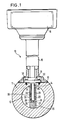
- the vortex flow meter 10 shown in FIG. 1 of the drawing has a measuring tube 11 shown in cross section, which is inserted into the pipeline through which the flow medium (liquid, gas) flows, the flow velocity of which is to be measured.
- the flow medium therefore flows in the representation of FIG. 1 perpendicular to the plane of the drawing through the flow channel 12 of the measuring tube 11.
- a flattened portion 13 is formed, from which a radial bore 14 into the interior of the Measuring tube is guided.
- a tubular housing support 15 is attached to the flattened portion 13 and carries a circuit housing 16 at the end opposite the measuring tube 11.
- a bluff body 20 is arranged, which extends diametrically over the entire diameter of the flow channel 12 and is firmly connected at both ends to the wall of the measuring tube 11.
- the bluff body 20 is designed in a manner known from vortex flow meters so that it generates Karman vortices in the flow medium.
- the bluff body 20 is a prismatic body of constant cross-section, which for example has the shape of an isosceles triangle, the base line of which faces the direction of flow. Two parallel vortex streets are created on the bluff body 20, the vertebrae of one vortex street being offset from the vortexes of the other vortex street.
- the measurement of the flow velocity is based on the fact that the distance between successive vortices in each vortex street is almost constant over a large range of flow velocities.
- the repetition frequency of the Kármán vortices is therefore proportional to the flow velocity.
- the vortex flow meter is therefore designed in such a way that it delivers a signal which is characteristic of the repetition frequency of the Kármán vortex.
- an axial cavity 21 is formed in the bluff body 20, which extends from the end of the bluff body lying at the top in FIG. 1 over the greater part of its length.
- the bluff body 20 is mounted in the measuring tube 11 so that the cavity 21 is coaxial with the bore 14.
- the cavity 21 is preferably cylindrical and has the same inner diameter as the bore 14. It is connected to the flow channel 12 of the measuring tube 11 via a plurality of passages which are guided through the bluff body 20 transversely to the direction of flow and are opposite one another in pairs.
- a first pair of passages 22, 23 lies approximately at the height of the axis of the flow channel 12, that is to say half the height of the bluff body 20.
- a second pair of passages 24, 25 lie at the upper end of the bluff body 20 directly on the wall of the measuring tube 11
- a third pair of passages 26, 27 are attached to the lower end of the cavity 21 at the level of the end wall 28 defining the cavity.
- a partition 29 of low height is formed on the end wall 28, which is parallel to the axis of the measuring tube 11.
- a swirl sensor 30 projects through the bore 14 into the cavity 21, where it extends almost to the partition 29.
- the vortex sensor 30 is supported by a flange 31 which is fastened to the flat 13 by means of screws 32.
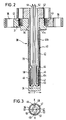
- the vortex sensor 30 is shown in more detail in the sectional view of FIG. 2. It consists of two components.
- the first component is a tubular sensor sleeve 33 which is connected to the flange 31 at one end and is sealed at the opposite end by an end wall 34.
- the flange 31 has one Center opening 35, which is coaxial to the sensor sleeve 33 and whose diameter is equal to the inner diameter of the sensor sleeve 33.
- the flange 31 has a plurality of holes 36 distributed around the circumference for the passage of the screws 32, with which it is fastened on the flat 13 (FIG. 1).
- the sensor sleeve 33 can be formed together with the end wall 34 in one piece with the flange 31 from the same material, for example from steel.
- the second component of the vortex sensor 30 is an electrode holder 40 which projects through the central opening 35 of the flange 31 into the interior of the sensor sleeve 33.
- the electrode holder 40 consists of a tube 41, which is connected to a second flange 42 and is preferably produced in one piece with the flange 42, for example likewise from steel.
- the flange 42 is fastened by means of screws 43 on the upper side of the flange 31, so that the electrode holder 34 projects through the central opening 35 into the interior of the sensor sleeve 33, where it extends up to the end wall 34.
- the tube 41 of the electrode holder 34 has three sections of different diameters.
- a first section 41a which sits in the central opening 35 of the flange 31, has an outer diameter which is equal to the diameter of the central opening 35, as a result of which a tight fit and a precise positioning of the electrode holder are ensured.
- the outer diameter of a second section 41b which makes up the largest part of the length of the electrode holder, is somewhat smaller than the inner diameter of the sensor sleeve 33, so that there is a narrow annular gap around the circumference between the section 41b and the sensor sleeve 33.
- the end section 41c of the tube 41 adjoins the middle section 41b via an inwardly projecting shoulder 44 and has one essential smaller diameter.
- This end section 41c carries an insulating sleeve 45, the outside diameter of which is somewhat smaller than the outside diameter of the middle section 41b.
- the insulating sleeve 45 can be made of ceramic, for example.
- two capacitor electrodes 46 and 47 are attached, which cover most of the circumferential surface and the lower end face of the insulating sleeve 45, but are mechanically and electrically separated from one another at two diametrically opposite locations by gaps 48, 49, like the lower end view of Fig. 3 shows.
- the capacitor electrodes 46, 47 can be formed by a metallization applied to the insulating sleeve 45 or by glued-on metal foils.
- the thicknesses of the insulating sleeve 45 and the capacitor electrodes 46, 47 are dimensioned such that an annular gap 50 of small gap width exists around the circumference between the capacitor electrodes 46, 47 and the inner surface of the sensor sleeve 33.
- Each capacitor electrode 46, 47 forms with the opposite section of the sensor sleeve 33, which acts as a counter electrode, a capacitor, the dielectric of which is air.
- the capacitance of each of these capacitors is proportional to the area of the capacitor electrode and inversely proportional to the gap width between the capacitor electrode and the sensor sleeve.
- the inner conductors of two shielded cables 51, 52 are soldered, which are guided through the hollow interior of the electrode holder 40 and through the tubular housing support 15 and the capacitor electrodes 46, 47 with connect the electronic evaluation circuit of the vortex flow meter housed in the circuit housing 16.
- the outer diameter of the sensor sleeve 33 of the swirl sensor 30 is somewhat smaller than the inner diameter of the cavity 21 in the bluff body 20, so that the sensor sleeve 33 is spaced on all sides from the wall of the cavity 21. There is thus a free space in the cavity 21 around the sensor sleeve 33, which is filled via the passages 22 to 27 with the flow medium flowing through the flow channel 12 of the measuring tube 11.
- the vortex sensor 30 is installed in the bluff body 20 so that the capacitor electrodes 46, 47 are symmetrical with respect to the axial center plane, which contains the axes of the measuring tube 11 and the bluff body 20 and is indicated in FIG. 3 by the line X-X.
- Each of the two components of the vortex sensor 30, namely the sensor sleeve 33 and the electrode holder 40, represents an elongated oscillating body which is held at one end and the free end of which is transversely to its longitudinal direction due to the action of external forces from the rest position shown in FIG. 2 can be deflected.
- the deflection consists in a bend, so that the sensor sleeve under the influence of the Vortex pressure fluctuations executes bending vibrations, the frequency of which is equal to the frequency of the pressure fluctuations.
- the bending vibration natural resonance frequency of the sensor sleeve 33 is very much higher than the highest occurring frequency of the vortex pressure fluctuations, so that the bending vibrations of the sensor sleeve 33 are excited subcritically and exactly follow the vortex pressure fluctuations according to frequency and phase.
- the amplitudes of the bending vibrations are very small, and the components of the vortex sensor 30 are designed and dimensioned such that the sensor sleeve 33 does not strike the wall of the cavity 21 or the electrode holder 40 when the vibration amplitudes are greatest.
- the upper passages 24, 25 and the lower passages 26, 27 in the bluff body 20 allow free circulation of the flow medium between the cavity 21 and the flow channel 12, so that the flow medium can dodge and follow the bending vibrations of the sensor sleeve 33 unhindered.
- the partition 29 between the lower passages 26 and 27 prevents direct pressure equalization around the lower end of the sensor sleeve.
- the electrode holder 40 arranged inside the tightly closed sensor sleeve 33 is not in contact with the flow medium and is therefore completely decoupled from its pressure fluctuations.
- the electrode holder 40 is therefore not caused to vibrate by the swirl pressure fluctuations, but remains at rest.
- the free end of the sensor sleeve 33 moves under the influence of the vortex pressure fluctuations relative to the fixed free end of the electrode holder, as indicated by the double arrow F in FIG. 2.
- the width of the air gap 50 between the electrodes 46, 47 and the opposite wall of the sensor sleeve 33 changes in opposite directions: If the The distance between the sensor sleeve 33 and the electrode 46 decreases, the distance between the sensor sleeve 33 and the electrode 47 increases at the same time, and vice versa. As a result, the capacitance values of the capacitors formed by the two electrodes 46, 47 and the sensor sleeve 33 also change in the opposite direction with the frequency of the vortex pressure fluctuations.
- the electronic evaluation circuit of the vortex flow meter housed in the circuit housing 16 can therefore generate an electrical signal based on these changes in capacitance which is characteristic of the frequency of the vortex pressure fluctuations and thus also of the flow velocity in the measuring tube 11.
- the two vibrating bodies can be jointly set into bending vibrations by such external forces.
- Such external forces can arise, in particular, from vibrations which set the measuring tube and thus the clamping point in a translatory oscillating movement in any axial direction or also try to rotate the two oscillating bodies about their clamping points.
- the free ends of the sensor sleeve 33 and the electrode holder 40 are deflected in the same direction by such external influences.
- the width of the gap 50 between the capacitor electrodes 46, 47 and the sensor sleeve 33 does not change noticeably in the case of these deflections in the same direction.
- Such external influences therefore do not cause a change in the two capacitances of the vortex sensor.
- there are also swirl pressure fluctuations at the same time as such external influences these cause an additional deflection of the sensor sleeve 33, that of the joint deflection of the two Vibrating body is superimposed and causes an opposite change in the two capacities.
- the vortex sensor described is therefore insensitive to vibrations in any direction of the axis or similar interference, but it enables reliable detection of the pressure fluctuations caused by Kármán's vortex even when such external interference is present.
- the electronic evaluation circuit is preferably designed in such a way that it generates a signal that depends on the difference between the two capacitances of the swirl sensor. Since the two capacitances change in opposite directions, the difference signal corresponds to twice the value of the capacitance change, while the base capacitances of the same size fall out of the difference signal. On the one hand, this enables a very precise and sensitive detection of the changes in capacity and, on the other hand, the elimination of the influence of further disturbance variables which can impair the function of the vortex flow meter. This applies in particular to the temperature and the static pressure of the flow medium.
- the vortex flow meter can be used under very different temperature and pressure conditions, and the temperature and pressure of the flow medium can also change within a wide range within the same area of application.
- Changes in the static pressure of the flow medium can change the cross section of the sensor sleeve due to deformation. This also changes the width of the air gap 50 and thus the value of the two basic capacities. Since, due to the symmetrical structure, such a cross-sectional change affects the two basic capacities in the same way, it is canceled out when the difference is formed, so that the differential signal is not influenced by changes in the static pressure.
- the described embodiment of the swirl sensor has a particularly good pressure resistance due to the cylindrical shape of the sensor sleeve and is therefore suitable for applications in which high pressures or large pressure fluctuations occur.
- Another cause of error in the signal evaluation can be that the shielded cables 51 and 52, via which the capacitor electrodes 46 and 47 are connected to the evaluation circuit, move relative to the electrode holder under the influence of vibrations or other interferences, so that from the Evaluation circuit variable interference capacities are detected.
- Such a relative movement of the cables can be prevented by a fixation, for example by means of a casting compound.
- the influence of interference capacities can also be active shielding of the cable can be switched off.
- the principle of active shielding is known to be that the potential of the shield is always tracked to the potential of the measuring electrode. In the upper area of the vortex sensor, such active shielding is definitely required to reduce the static capacitance and touch sensitivity.
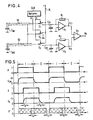
- Fig. 4 shows a capacitance measuring circuit which is particularly well suited as an input stage of the electronic evaluation circuit of the vortex flow meter described.
- This capacitance measuring circuit is designed according to the principle of "switched capacitors" known from DE-A-31 43 114. It enables a very sensitive and precise measurement of capacitance changes, even if they are very small 4 so that it enables active shielding in a very simple manner.
- the measuring capacitance C M1 being the capacitance that exists between the sensor sleeve 33 connected to ground and the capacitor electrode 46 connected to the evaluation circuit via the shielded cable 51.
- the measuring capacitance C M2 is the capacitance that exists between the sensor sleeve 33 connected to ground and the capacitor electrode 47 connected to the evaluation circuit via the shielded cable 52.
- the shields of the two cables 51 and 52 are indicated by dashed lines.
- the capacitance measuring circuit contains two completely identical circuit branches, each of which is assigned to one of the two measuring capacitors.
- the one with the measuring capacity C M1 the cable 51 connected circuit branch contains a switch S1, which in the one position, which is shown in Fig. 4, connects the inner conductor of the cable 51 to a terminal KL, which leads to a constant positive DC voltage + U, which, for example, the operating voltage the circuit is.
- the switch S 1 connects the measuring capacitance C M1 to a storage capacitor C 1, the capacitance of which is very large compared to the measuring capacitance C M1 .
- the inverting input of an operational amplifier A1 is also connected, the non-inverting input of which is connected to ground and the feedback circuit between the output and the inverting input contains a resistor R1.
- the circuit branch assigned to the measuring capacitance C M2 contains, in a corresponding manner, a changeover switch S2, a storage capacitor C02 and an operational amplifier A2 with a feedback resistor R2.
- the outputs of the two operational amplifiers A1 and A2 are connected to the two inputs of a differential amplifier A3.
- the two switches S1 and S2 are actuated by a control signal A, which is output at an output of a clock generator CLK.
- the clock CLK outputs a control signal B at a second output, which actuates a changeover switch S3, which puts the shields of the two cables 51 and 52 in one position to the voltage + U of the terminal KL and in the other position to ground.
- the diagram A shows the time course of the control signal A, which actuates the two switches S1 and S2.
- the control signal A periodically takes on two states 0 or 1, assuming that each changeover switch S 1, S 2 at the value 1 of the control signal A has the position shown in FIG. 4, in which it has the assigned measuring capacitance C M1 , C M2 the terminal KL connects while it disconnects the assigned measuring capacitance from the terminal KL at the value 0 of the control signal A and therefore connects it to the assigned storage capacitor C01 or C02.
- the diagram U CM of Fig. 5 shows the time course of the voltage at each measuring capacitance C M1, C M1 and thus also the voltage on the inner conductor of the associated cable 51 or 52. If you only consider the first circuit branch, then in each Phase I, which corresponds to the value 1 of the control signal A, the measuring capacitance C M1 charged to the voltage + U. Charging is not delay-free due to the inevitable time constant of the charging circuit, but the duration of phase 1 is dimensioned so large that the voltage U CM at the measuring capacitance C M1 certainly reaches the full value + U.
- phase II which corresponds to the value 0 of the control signal A
- the measuring capacitance C M1 discharges with the corresponding time constant into the storage capacitor C01. Since the capacitance of the storage capacitor C01 is very large against the measuring capacitance C M1 , the voltage across these two capacitances after the charge equalization is very small against the voltage + U.
- the duration of phase II which is preferably equal to the duration of phase I, is so large that the complete charge equalization can take place with certainty.
- the measuring capacitance C M1 is recharged to the voltage + U, while the charge of the storage capacitor C01 is slowly dissipated by the operational amplifier A1 acting as a current-voltage converter.
- the charge is equalized by a current which flows through the resistor R1 and causes the voltage across the storage capacitor C01 to be kept substantially at an average of zero.
- the current flowing through the resistor R 1 is equal to the mean value of the current which is discharged from the measuring capacitance C M1 .
- the output voltage of the operational amplifier A 1 assumes a value U C1 which is exactly proportional to the measuring capacitance C M1 .
- the output voltage of the operational amplifier A2 of the other circuit branch assumes a value U C2 , which is exactly proportional to the value of the measuring capacitance C M2 .
- the differential amplifier A3 forms the difference between the two voltages U C1 U C 2 and supplies a voltage U D at the output which is exactly proportional to the difference between the two measuring capacitances C M1 , C M2 .
- the capacitance of each of the two shielded cables 51, 52 is added to the measurement capacitance, and changes in the capacitance of the cable affect the measurement.
- active shielding is used in the capacitance measuring circuit of FIG. 4, in that the potential of the cable shield follows the potential on the shielded inner conductor of the cable. According to the prior art, such active shielding is achieved by continuously scanning the potential of the shielded line and applying it via an impedance converter the shield is placed.
- the active shielding is carried out in a particularly simple and effective manner with the aid of the switch S 3 actuated by the control signal B, without the need to return the potential of the shielded line.
- Diagram B of FIG. 5 shows the temporal course of control signal B, which periodically takes on the values 0 and 1 alternately with the same repetition frequency as control signal A.
- the diagram U K of FIG. 5 shows the time profile of the voltage on the shields of the two cables 51 and 52.
- control signals A and B are exactly in phase, the voltages U CM and U K also have essentially the same time profile. This fulfills the condition of active shielding that the potential of the shield constantly follows the potential of the shielded electrode. In Fig. 5, however, the control signals A and B are deliberately out of phase with each other to show that it is not important to maintain exact temporal relationships.
- the requirements for the timing of the control signal B in relation to the control signal A are therefore not critical. It is only necessary to adhere to the temporal conditions that the shielding voltage U K must have reached the voltage value + U before the start of each phase II and the voltage value 0 before the start of each phase I. Taking into account the recharging time T K, this means that the control signal B at the latest by the time period T K before the beginning of each phase II to the value 1 and at least the time period T K before the beginning of each phase I must be brought up to 0.
- the control signal B can have any values in the cross-hatched areas and only has to have the specified signal value in the areas of the duration T K marked with “1” or “0”.
- the switch S1, S2, S3 are shown in Fig. 4 only for clarity as a mechanical switch.
- these are very fast electronic switches, for example MOS field effect transistors. Since such electronic switches do not act as change-over switches, but as simple on-off switches, 4 must be replaced by two such electronic switches, which are driven in phase opposition by the control signal in question. To ensure that the two electronic switches are not open at the same time, it may then be expedient to insert short intervals between the successive switching phases, in which the two electronic switches, which together form a changeover switch, are blocked at the same time.
- the switch S3 can also be replaced by a threshold comparator, which receives the control signal A and outputs at its output, depending on the value of its input signal, either the voltage + U or the voltage 0. This further simplifies the circuit.
- the two components of the vortex sensor that are adjustable relative to one another that is to say the sensor sleeve 33 and the electrode holder 34, form a capacitive sensor acting as a mechano-electrical converter, which converts relative adjustments between the two components into changes in capacitance.
- the formation of two mutually changeable measuring capacitances with the aid of two capacitor electrodes results in the advantage that the capacitance measuring circuit can form a mean-free difference signal which only represents the changes in capacitance.
- this measure is by no means mandatory; the measurement of the frequency of the vortex pressure fluctuations is also possible if the electrode holder carries only one capacitor electrode and thus only one measuring capacity is available.
- the second circuit branch of the capacitance measuring circuit of FIG. 4 is simply omitted and the information about the flow rate is contained in the changes in the output voltage of the remaining circuit branch.
- the sensor sleeve 33 With regard to the compensation of vibrations and other disturbing influences as well as with regard to the sensitivity of the vortex flow meter, it is particularly advantageous to manufacture the sensor sleeve 33 from titanium.
- the modulus of elasticity of titanium is significantly smaller than the modulus of elasticity of steel; therefore, a sensor sleeve made of titanium experiences a much greater deflection under the influence of the vortex pressure fluctuations than a sensor sleeve of the same dimensions made of steel. Since the changes in capacitance are proportional to the deflection, the sensitivity of the swirl sensor is correspondingly greater.
- the ratio of density to modulus of elasticity in titanium is of the same order of magnitude as in steel, so that a vibrating body made of titanium exhibits a similar vibration behavior to a vibrating body made of steel.
- a sensor sleeve made of titanium can therefore be combined very well with an electrode holder made of steel in order to compensate for vibrations and other interferences.
- the advantageous properties of titanium in particular the very good corrosion resistance and the high fatigue strength, can be used in this way for the sensor sleeve.
Landscapes
- Physics & Mathematics (AREA)
- General Physics & Mathematics (AREA)
- Fluid Mechanics (AREA)
- Engineering & Computer Science (AREA)
- Aviation & Aerospace Engineering (AREA)
- Measuring Fluid Pressure (AREA)
- Measurement Of Resistance Or Impedance (AREA)
Applications Claiming Priority (2)
| Application Number | Priority Date | Filing Date | Title |
|---|---|---|---|
| DE19853544198 DE3544198A1 (de) | 1985-12-13 | 1985-12-13 | Wirbelstroemungsmesser |
| DE3544198 | 1985-12-13 |
Publications (3)
| Publication Number | Publication Date |
|---|---|
| EP0229933A2 EP0229933A2 (de) | 1987-07-29 |
| EP0229933A3 EP0229933A3 (en) | 1989-05-10 |
| EP0229933B1 true EP0229933B1 (de) | 1991-04-24 |
Family
ID=6288409
Family Applications (1)
| Application Number | Title | Priority Date | Filing Date |
|---|---|---|---|
| EP86116478A Expired - Lifetime EP0229933B1 (de) | 1985-12-13 | 1986-11-27 | Wirbelströmungsmesser |
Country Status (5)
| Country | Link |
|---|---|
| US (1) | US4716770A (OSRAM) |
| EP (1) | EP0229933B1 (OSRAM) |
| JP (1) | JPS62215829A (OSRAM) |
| CN (1) | CN1005221B (OSRAM) |
| DE (2) | DE3544198A1 (OSRAM) |
Cited By (1)
| Publication number | Priority date | Publication date | Assignee | Title |
|---|---|---|---|---|
| US8024136B2 (en) | 2006-05-12 | 2011-09-20 | Endress + Hauser Flowtec Ag | Method for signal processing of measurement signals of a vortex flow transducer |
Families Citing this family (50)
| Publication number | Priority date | Publication date | Assignee | Title |
|---|---|---|---|---|
| GB2211612B (en) * | 1987-10-27 | 1991-10-23 | Fuji Electric Co Ltd | Karman vortex flow meter |
| JPH0613449Y2 (ja) * | 1988-03-04 | 1994-04-06 | オーバル機器工業株式会社 | 渦流量計 |
| US5095760A (en) * | 1989-05-08 | 1992-03-17 | Lew Hyok S | Vortex flowmeter with dual sensors |
| ES2078015T3 (es) * | 1992-02-27 | 1995-12-01 | Flowtec Ag | Aparato de medida para las corrientes turbulentas. |
| US5347873A (en) * | 1993-04-09 | 1994-09-20 | Badger Meter, Inc. | Double wing vortex flowmeter with strouhal number corrector |
| CH687420A5 (de) * | 1993-11-22 | 1996-11-29 | Fischer Georg Rohrleitung | Einrichtung zur Messung der Geschwindigkeit eines Fluides. |
| EP0682772A1 (de) * | 1993-12-07 | 1995-11-22 | Endress + Hauser Flowtec AG | Strömungsmessonde |
| US6220103B1 (en) | 1996-07-15 | 2001-04-24 | Engineering Measurements Company | Vortex detector and flow meter |
| ES2133006T3 (es) * | 1996-11-08 | 1999-08-16 | Flowtec Ag | Detector de circulacion turbulenta. |
| US5869772A (en) * | 1996-11-27 | 1999-02-09 | Storer; William James A. | Vortex flowmeter including cantilevered vortex and vibration sensing beams |
| US5804740A (en) * | 1997-01-17 | 1998-09-08 | The Foxboro Company | Capacitive vortex mass flow sensor |
| US5959219A (en) * | 1997-07-28 | 1999-09-28 | Saunders; David N. | Capacitive gas flow sensor |
| US6352000B1 (en) * | 1998-08-12 | 2002-03-05 | Flowtec Ag | Vortex flow sensor |
| US6405794B1 (en) * | 1999-03-07 | 2002-06-18 | Korea Institute Of Science And Technology | Acoustic convection apparatus |
| RU2219501C2 (ru) * | 2002-02-20 | 2003-12-20 | Козлов Сергей Павлович | Вихревой расходомер (варианты) |
| DE10240189A1 (de) * | 2002-08-28 | 2004-03-04 | Endress + Hauser Flowtec Ag, Reinach | Verfahren zum Ermitteln eines Massendurchflusses eines in einer Rohrleitung strömenden Fluids |
| DE10250065A1 (de) * | 2002-10-25 | 2004-05-06 | Endress + Hauser Flowtec Ag, Reinach | Prozeß-Meßgerät |
| US7363811B2 (en) * | 2005-04-07 | 2008-04-29 | Endress + Hauser Flowtec Ag | Measurement pickup |
| RU2351900C2 (ru) * | 2006-08-07 | 2009-04-10 | Алексей Федорович Писарев | Расходомер жидких сред в трубопроводах |
| DE102007021099A1 (de) | 2007-05-03 | 2008-11-13 | Endress + Hauser (Deutschland) Ag + Co. Kg | Verfahren zum Inbetriebnehmen und/oder Rekonfigurieren eines programmierbaren Feldmeßgeräts |
| DE102007030700A1 (de) | 2007-06-30 | 2009-05-07 | Endress + Hauser Flowtec Ag | Meßsystem für ein in einer Prozeßleitung strömendes Medium |
| DE102007030691A1 (de) | 2007-06-30 | 2009-01-02 | Endress + Hauser Flowtec Ag | Meßsystem für ein in einer Prozeßleitung strömendes Medium |
| DE102007030699A1 (de) | 2007-06-30 | 2009-01-15 | Endress + Hauser Flowtec Ag | Meßsystem für ein in einer Prozeßleitung strömendes Medium |
| DE102007030690A1 (de) | 2007-06-30 | 2009-05-07 | Endress + Hauser Flowtec Ag | Meßsystem für ein in einer Prozeßleitung strömendes Medium |
| DE102007063372A1 (de) | 2007-12-30 | 2009-07-02 | Endress + Hauser Flowtec Ag | Meßsystem für ein in einer Prozeßleitung strömendes Medium |
| DE102007037166A1 (de) | 2007-08-07 | 2009-02-19 | Endress + Hauser Flowtec Ag | Meßgerät |
| DE102007058608A1 (de) | 2007-12-04 | 2009-06-10 | Endress + Hauser Flowtec Ag | Elektrisches Gerät |
| DE102008022373A1 (de) | 2008-05-06 | 2009-11-12 | Endress + Hauser Flowtec Ag | Meßgerät sowie Verfahren zum Überwachen eines Meßgeräts |
| DE102009001525A1 (de) * | 2009-03-12 | 2010-09-16 | Endress + Hauser Flowtec Ag | Verfahren und Wirbelströmungsmessgerät zum Überwachen und/oder Messen einer Wandströmung eines in einer Rohrleitung strömenden, zwei- oder mehrphasigen Mediums |
| DE102009002289A1 (de) | 2009-04-08 | 2010-10-14 | Endress + Hauser Flowtec Ag | Verfahren zum Ermitteln einer Periodendauer eines Meßsignals |
| WO2011016813A1 (en) * | 2009-08-07 | 2011-02-10 | Halliburton Energy Services, Inc. | Annulus vortex flowmeter |
| US8056424B2 (en) * | 2009-09-17 | 2011-11-15 | Sean P. Palacios | Multi-channel flow sensor with extended flow range and faster response |
| RU2496113C2 (ru) * | 2010-04-15 | 2013-10-20 | Алексей Федорович Писарев | Расходомер жидких и газовых сред в напорных трубопроводах |
| DE102010030924A1 (de) | 2010-06-21 | 2011-12-22 | Endress + Hauser Flowtec Ag | Elektronik-Gehäuse für ein elektronisches Gerät bzw. damit gebildetes Gerät |
| DE102011076838A1 (de) | 2011-05-31 | 2012-12-06 | Endress + Hauser Flowtec Ag | Meßgerät-Elektronik für ein Meßgerät-Gerät sowie damit gebildetes Meßgerät-Gerät |
| DE102011080894A1 (de) * | 2011-08-12 | 2013-02-14 | Endress + Hauser Flowtec Ag | Sensor-Modul zum Messen und/oder Überwachen von Parametern von in Rohrleitungen strömenden Medien sowie damit gebildetes Meßsystem |
| DE102013013476A1 (de) * | 2013-08-15 | 2015-02-19 | Endress + Hauser Flowtec Ag | Wirbelströmungsmesssensor und Wirbelströmungsmessaufnehmer zur Messung der Strömungsgeschwindigkeit eines fluids |
| DE102013110243A1 (de) * | 2013-09-17 | 2015-04-02 | Endress + Hauser Flowtec Ag | Verfahren zur Überwachung eines Messgerätes der Automatisierungstechnik |
| CN103760233A (zh) * | 2014-01-27 | 2014-04-30 | 爱德森(厦门)电子有限公司 | 一种穿过式涡流传感器的屏蔽装置 |
| DE102014119260A1 (de) | 2014-12-19 | 2016-06-23 | Endress + Hauser Flowtec Ag | Anschlußvorrichtung für ein Elektronik-Gehäuse sowie Meßwandler bzw. Feldgerät mit einer solchen Anschlußvorrichtung |
| DE102015121462A1 (de) | 2015-12-09 | 2017-06-14 | Endress + Hauser Flowtec Ag | Anschlußvorrichtung zum mechanischen Verbinden eines Elektronik-Gehäuses und eines Meßwandler-Gehäuses, Meßwandler mit einer einer solchen Anschlußvorrichtung bzw. damit gebildetes Feldgerät |
| CN110007153B (zh) * | 2019-03-22 | 2024-07-26 | 金华职业技术学院 | 一种材料介电谱测量的方法 |
| CN110345973B (zh) * | 2019-07-25 | 2021-03-16 | 深圳市普颂电子有限公司 | 电涡流传感器及检测方法 |
| CN110702271B (zh) * | 2019-11-14 | 2020-11-13 | 苏州市相城区阳澄产业园发展有限公司 | 一种随流速自动调节的管道液体温度检测装置 |
| CN110988377A (zh) * | 2019-12-31 | 2020-04-10 | 苏州幕特克自动化设备有限公司 | 一种应用于高频震动工况下的流速检测仪 |
| DE102020134066A1 (de) * | 2020-12-17 | 2022-06-23 | Endress+Hauser Flowtec Ag | Vortex-Durchflussmessgerät und Verfahren zum Überprüfen eines Vortex-Durchflussmessgeräts |
| DE102022119145A1 (de) | 2022-07-29 | 2024-02-01 | Endress+Hauser Flowtec Ag | Anschlussschaltung für ein Feldgerät und Feldgerät |
| DE102022127160A1 (de) | 2022-10-18 | 2024-04-18 | Endress+Hauser Flowtec Ag | Sensorelement |
| DE102022131694A1 (de) | 2022-11-30 | 2024-06-06 | Endress+Hauser Flowtec Ag | Kapazitive Sensorbaugruppe für ein Feldgerät und Feldgerät |
| DE102023114029A1 (de) | 2023-05-26 | 2024-11-28 | Endress+Hauser Flowtec Ag | Vorrichtung zur Bestimmung und/oder Überwachung zumindest einer Prozessgröße |
Family Cites Families (9)
| Publication number | Priority date | Publication date | Assignee | Title |
|---|---|---|---|---|
| US3927566A (en) * | 1971-06-17 | 1975-12-23 | Kent Instruments Ltd | Flowmeters |
| US4186599A (en) * | 1976-12-29 | 1980-02-05 | Rosemount Inc. | Vortex shedding flowmeter assembly |
| JPS6029046B2 (ja) * | 1980-01-24 | 1985-07-08 | 横河電機株式会社 | 流速流量測定装置 |
| GB2087084B (en) * | 1980-11-07 | 1985-04-03 | Mestra Ag | Measuring capacitance of a circuit element |
| US4362061A (en) * | 1981-02-04 | 1982-12-07 | Yokogawa Electric Works, Ltd. | Vortex shedding flow measuring device |
| JPS58124916A (ja) * | 1982-01-21 | 1983-07-25 | Yokogawa Hokushin Electric Corp | 流速流量測定装置 |
| JPS5918422A (ja) * | 1982-07-22 | 1984-01-30 | Oval Eng Co Ltd | 渦流量計用振動補償装置 |
| DE3377936D1 (de) * | 1982-11-25 | 1988-10-13 | Oval Eng Co Ltd | Vortex flow meter |
| DE3544187A1 (de) * | 1985-12-13 | 1987-06-19 | Flowtec Ag | Kapazitaetsmessschaltung |
-
1985
- 1985-12-13 DE DE19853544198 patent/DE3544198A1/de not_active Withdrawn
-
1986
- 1986-11-27 EP EP86116478A patent/EP0229933B1/de not_active Expired - Lifetime
- 1986-11-27 DE DE8686116478T patent/DE3678930D1/de not_active Expired - Fee Related
- 1986-12-11 CN CN86108400.4A patent/CN1005221B/zh not_active Expired
- 1986-12-11 US US06/940,581 patent/US4716770A/en not_active Expired - Lifetime
- 1986-12-12 JP JP61295134A patent/JPS62215829A/ja active Granted
Cited By (1)
| Publication number | Priority date | Publication date | Assignee | Title |
|---|---|---|---|---|
| US8024136B2 (en) | 2006-05-12 | 2011-09-20 | Endress + Hauser Flowtec Ag | Method for signal processing of measurement signals of a vortex flow transducer |
Also Published As
| Publication number | Publication date |
|---|---|
| CN86108400A (zh) | 1987-08-12 |
| EP0229933A3 (en) | 1989-05-10 |
| EP0229933A2 (de) | 1987-07-29 |
| JPH0467129B2 (OSRAM) | 1992-10-27 |
| CN1005221B (zh) | 1989-09-20 |
| DE3544198A1 (de) | 1987-06-19 |
| JPS62215829A (ja) | 1987-09-22 |
| US4716770A (en) | 1988-01-05 |
| DE3678930D1 (de) | 1991-05-29 |
Similar Documents
| Publication | Publication Date | Title |
|---|---|---|
| EP0229933B1 (de) | Wirbelströmungsmesser | |
| DE60216263T2 (de) | Positionsdetektor | |
| DE3433148C2 (de) | Anordnung zur Erfassung räumlicher Inhomogenitäten in einem Dielektrikum | |
| DE3014038C2 (de) | Pendelbeschleunigungsmesser | |
| DE1926798C3 (de) | Durchflußmeßgerät | |
| DE69010568T2 (de) | Keramisches resonanzartiges Elektrostatikfühlergerät. | |
| EP0503272B1 (de) | Schaltungsanordnung zur Messung des Quotienten der Kapazitätswerte zweier Kondensatoren | |
| DE10240189A1 (de) | Verfahren zum Ermitteln eines Massendurchflusses eines in einer Rohrleitung strömenden Fluids | |
| DE3544187A1 (de) | Kapazitaetsmessschaltung | |
| DE3343310A1 (de) | Ultraschall-wegmesser | |
| DE3107925A1 (de) | Mechanisch/elektrischer wandler mit sechs freiheitsgraden | |
| DE2141397C3 (de) | Vibrationsdichtemeßgerät | |
| DE3906679A1 (de) | Beschleunigungsmesser | |
| DE4009697C2 (OSRAM) | ||
| DE3642771C2 (OSRAM) | ||
| DE2922566A1 (de) | Druckwandler, insbesondere wirkdruckgeber | |
| DE2903688C3 (de) | Kapazitätsdifferenz-Messer | |
| DE2603185C2 (de) | Anordnung zur kapazitiven Messung des Füllstandes eines Behälters | |
| EP0557671B1 (de) | Wirbelströmungsmessgerät | |
| DE69635043T2 (de) | Elektromagnetischer Durchflussmesser mit Unterdrückung des Einflusses von Schwankungen der Offset-Spannung | |
| DE1264819B (de) | Piezoelektrischer Druckwandler | |
| EP1145015B1 (de) | Beschleunigungsmesseinrichtung | |
| DE2827985C2 (de) | Strömungsmesser | |
| DE3822076C1 (OSRAM) | ||
| WO1989005447A1 (fr) | Dispositif de mesure de distances |
Legal Events
| Date | Code | Title | Description |
|---|---|---|---|
| PUAI | Public reference made under article 153(3) epc to a published international application that has entered the european phase |
Free format text: ORIGINAL CODE: 0009012 |
|
| AK | Designated contracting states |
Kind code of ref document: A2 Designated state(s): CH DE FR GB IT LI NL |
|
| ITCL | It: translation for ep claims filed |
Representative=s name: BARZANO' E ZANARDO MILANO S.P.A. |
|
| TCNL | Nl: translation of patent claims filed | ||
| EL | Fr: translation of claims filed | ||
| PUAL | Search report despatched |
Free format text: ORIGINAL CODE: 0009013 |
|
| AK | Designated contracting states |
Kind code of ref document: A3 Designated state(s): CH DE FR GB IT LI NL |
|
| 17P | Request for examination filed |
Effective date: 19890422 |
|
| 17Q | First examination report despatched |
Effective date: 19900130 |
|
| GRAA | (expected) grant |
Free format text: ORIGINAL CODE: 0009210 |
|
| ITF | It: translation for a ep patent filed | ||
| AK | Designated contracting states |
Kind code of ref document: B1 Designated state(s): CH DE FR GB IT LI NL |
|
| REF | Corresponds to: |
Ref document number: 3678930 Country of ref document: DE Date of ref document: 19910529 |
|
| GBT | Gb: translation of ep patent filed (gb section 77(6)(a)/1977) | ||
| ET | Fr: translation filed | ||
| PLBE | No opposition filed within time limit |
Free format text: ORIGINAL CODE: 0009261 |
|
| STAA | Information on the status of an ep patent application or granted ep patent |
Free format text: STATUS: NO OPPOSITION FILED WITHIN TIME LIMIT |
|
| REG | Reference to a national code |
Ref country code: CH Ref legal event code: PFA Free format text: ENDRESS + HAUSER FLOWTEC AG |
|
| 26N | No opposition filed | ||
| ITPR | It: changes in ownership of a european patent |
Owner name: CAMBIO RAGIONE SOCIALE;ENDRESS + HAUSER FLOWTEC AG |
|
| REG | Reference to a national code |
Ref country code: FR Ref legal event code: CD |
|
| NLT1 | Nl: modifications of names registered in virtue of documents presented to the patent office pursuant to art. 16 a, paragraph 1 |
Owner name: ENDRESS + HAUSER FLOWTEC AG TE REINACH, ZWITSERLAN |
|
| REG | Reference to a national code |
Ref country code: GB Ref legal event code: IF02 |
|
| PGFP | Annual fee paid to national office [announced via postgrant information from national office to epo] |
Ref country code: DE Payment date: 20041105 Year of fee payment: 19 |
|
| PGFP | Annual fee paid to national office [announced via postgrant information from national office to epo] |
Ref country code: CH Payment date: 20041109 Year of fee payment: 19 |
|
| PGFP | Annual fee paid to national office [announced via postgrant information from national office to epo] |
Ref country code: NL Payment date: 20041111 Year of fee payment: 19 |
|
| PGFP | Annual fee paid to national office [announced via postgrant information from national office to epo] |
Ref country code: FR Payment date: 20041112 Year of fee payment: 19 |
|
| PGFP | Annual fee paid to national office [announced via postgrant information from national office to epo] |
Ref country code: GB Payment date: 20041122 Year of fee payment: 19 |
|
| PG25 | Lapsed in a contracting state [announced via postgrant information from national office to epo] |
Ref country code: IT Free format text: LAPSE BECAUSE OF NON-PAYMENT OF DUE FEES;WARNING: LAPSES OF ITALIAN PATENTS WITH EFFECTIVE DATE BEFORE 2007 MAY HAVE OCCURRED AT ANY TIME BEFORE 2007. THE CORRECT EFFECTIVE DATE MAY BE DIFFERENT FROM THE ONE RECORDED. Effective date: 20051127 Ref country code: GB Free format text: LAPSE BECAUSE OF NON-PAYMENT OF DUE FEES Effective date: 20051127 |
|
| PG25 | Lapsed in a contracting state [announced via postgrant information from national office to epo] |
Ref country code: LI Free format text: LAPSE BECAUSE OF NON-PAYMENT OF DUE FEES Effective date: 20051130 Ref country code: CH Free format text: LAPSE BECAUSE OF NON-PAYMENT OF DUE FEES Effective date: 20051130 |
|
| PG25 | Lapsed in a contracting state [announced via postgrant information from national office to epo] |
Ref country code: NL Free format text: LAPSE BECAUSE OF NON-PAYMENT OF DUE FEES Effective date: 20060601 Ref country code: DE Free format text: LAPSE BECAUSE OF NON-PAYMENT OF DUE FEES Effective date: 20060601 |
|
| REG | Reference to a national code |
Ref country code: CH Ref legal event code: PL |
|
| GBPC | Gb: european patent ceased through non-payment of renewal fee |
Effective date: 20051127 |
|
| PG25 | Lapsed in a contracting state [announced via postgrant information from national office to epo] |
Ref country code: FR Free format text: LAPSE BECAUSE OF NON-PAYMENT OF DUE FEES Effective date: 20060731 |
|
| NLV4 | Nl: lapsed or anulled due to non-payment of the annual fee |
Effective date: 20060601 |
|
| REG | Reference to a national code |
Ref country code: FR Ref legal event code: ST Effective date: 20060731 |