EP0229933B1 - Vortex flow meter - Google Patents
Vortex flow meter Download PDFInfo
- Publication number
- EP0229933B1 EP0229933B1 EP86116478A EP86116478A EP0229933B1 EP 0229933 B1 EP0229933 B1 EP 0229933B1 EP 86116478 A EP86116478 A EP 86116478A EP 86116478 A EP86116478 A EP 86116478A EP 0229933 B1 EP0229933 B1 EP 0229933B1
- Authority
- EP
- European Patent Office
- Prior art keywords
- capacitance
- vortex
- sensor
- pressure fluctuations
- measuring
- Prior art date
- Legal status (The legal status is an assumption and is not a legal conclusion. Google has not performed a legal analysis and makes no representation as to the accuracy of the status listed.)
- Expired - Lifetime
Links
Images
Classifications
-
- G—PHYSICS
- G01—MEASURING; TESTING
- G01P—MEASURING LINEAR OR ANGULAR SPEED, ACCELERATION, DECELERATION, OR SHOCK; INDICATING PRESENCE, ABSENCE, OR DIRECTION, OF MOVEMENT
- G01P5/00—Measuring speed of fluids, e.g. of air stream; Measuring speed of bodies relative to fluids, e.g. of ship, of aircraft
- G01P5/01—Measuring speed of fluids, e.g. of air stream; Measuring speed of bodies relative to fluids, e.g. of ship, of aircraft by using swirlflowmeter
-
- G—PHYSICS
- G01—MEASURING; TESTING
- G01F—MEASURING VOLUME, VOLUME FLOW, MASS FLOW OR LIQUID LEVEL; METERING BY VOLUME
- G01F1/00—Measuring the volume flow or mass flow of fluid or fluent solid material wherein the fluid passes through a meter in a continuous flow
- G01F1/05—Measuring the volume flow or mass flow of fluid or fluent solid material wherein the fluid passes through a meter in a continuous flow by using mechanical effects
- G01F1/20—Measuring the volume flow or mass flow of fluid or fluent solid material wherein the fluid passes through a meter in a continuous flow by using mechanical effects by detection of dynamic effects of the flow
- G01F1/32—Measuring the volume flow or mass flow of fluid or fluent solid material wherein the fluid passes through a meter in a continuous flow by using mechanical effects by detection of dynamic effects of the flow using swirl flowmeters
- G01F1/325—Means for detecting quantities used as proxy variables for swirl
- G01F1/3259—Means for detecting quantities used as proxy variables for swirl for detecting fluid pressure oscillations
Definitions
- the invention relates to a vortex flow meter for measuring the rate of disturbance of a flow medium in a pipeline, with a bluff body arranged in the flow channel of the pipeline, which is designed to generate Kármán vortices, a vortex sensor which acts on the pressure fluctuations generated by the Kármán vortices responds, wherein the vortex sensor has a first oscillating body, which can be deflected by the vortex pressure fluctuations, and a capacitive transducer with an electrode holder, which is arranged in a cavity of the first oscillating body which is sealed off from the flow medium and carries at least one capacitor electrode which corresponds to an electrode section of the lies opposite the first vibrating body in such a way that it forms a measuring capacity with it, which is caused by a deflection of the first one caused by the vortex pressure fluctuations Vibrating body is variable, the electrode holder being designed as a second vibrating body, which is decoupled from the swirl pressure fluctuations, and with an evaluation circuit which contains a
- the bluff body itself forms the first vibrating body of the vortex sensor.
- the bluff body therefore contains a cavity which is sealed off from the flow medium and in which the electrode holder of the capacitive transducer is arranged.
- the bluff body is extended by an approach to more than twice the diameter of the flow channel and supported at both ends so that it is caused by the vortex pressure fluctuations in bending vibrations.
- the oscillating movement of the bluff body relative to the electrode holder fixed in its cavity results in changes in capacitance between the electrodes carried by the electrode holder and the wall sections of the bluff body cavity opposite these electrodes.
- the electrode holder is rod-shaped and clamped at one end, so that it forms a second oscillating body which, under the influence of external forces, can also be set into bending vibrations by which its free end carrying the electrodes is deflected.
- the aim is to ensure that the deflections of these two vibrating bodies at the height of the electrodes are approximately the same size and the same direction under the influence of vibrations or similar interfering influences, so that such deflections do not occur Result in changes in capacity.
- this condition can only be met with difficulty and incompletely, because in particular the formation of the first vibrating body is predominantly determined by its function as a bluff body.
- the vibration amplitudes that can be achieved by the swirl pressure fluctuations and consequently the changes in capacitance caused thereby are relatively small, which affects the sensitivity of the swirl sensor.
- the vibration behavior of the electrode holder cannot be adapted well to the vibration behavior of the bluff body, so that the compensation of vibrations and similar disturbances is only possible in an imperfect manner. It is also often undesirable, especially with larger nominal widths of the flow channel, for the bluff body to vibrate itself.
- a second piezoelectric transducer of the same type is arranged outside the pipeline in such a way that it responds only to the vibrations and interferences, but not to the deflections of the pressure-receiving plate. This results in a considerable length of the swirl sensor, a large part of which is outside the pipeline.
- the capacitance measuring circuit of the vortex flow meter described in US-A-4 362 061 contains a bridge circuit which contains the two capacitances in two bridge branches which are formed by two pairs of electrodes arranged on opposite sides of the two oscillating bodies. An AC voltage is applied to one bridge diagonal, so that an AC voltage is obtained on the other bridge diagonal, which depends on the difference between the two capacitances. Since the two capacitances change in opposite directions as a result of the oscillating movements of the two oscillating bodies, the bridge output AC voltage is amplitude-modulated with the frequency of the swirl pressure fluctuations.
- This capacitance measuring circuit contains a switching arrangement for each measuring capacitance, which applies the measuring capacitance with a predetermined switching frequency periodically alternately for charging to a constant voltage and connects for discharging with a storage capacitor, the capacitance of which is large compared to the measuring capacitance and the terminal voltage of which is essentially due to a controlled discharge current is kept at a constant reference potential.
- the capacitance measurement is based on the measurement of the average discharge current of the measurement capacitance which is periodically alternately charged and discharged to a constant voltage.
- the average discharge current is usually converted by a current-voltage converter into a voltage which is proportional to the measuring capacity.
- the object of the invention is to provide a vortex flow meter of the type mentioned, which results in an optimal compensation of vibrations and similar mechanical disturbances at a very small height without the function of the bluff body being impaired, and in which the influence of stray capacities and interference fields on the measurement result is effectively turned off with little effort.
- this object is achieved in that a cavity is formed in the bluff body, which is connected via passages to the flow channel of the pipeline, that the first vibrating body is a sensor sleeve surrounding the electrode holder, which is arranged in the cavity of the bluff body, that the or each capacitor electrode is connected to the capacitance measuring circuit by a shielded cable, that the capacitance measuring circuit contains a switching arrangement for each measuring capacitance, which alternately applies the measuring capacitance to a constant voltage alternately for charging at a predetermined switching frequency and connects it to a storage capacitor for discharging, the capacitance of which is large compared to the measuring capacitance is and its terminal voltage is maintained at a constant reference potential by a controlled discharge current, the size of the discharge current being proportional to the measuring capacitance and representing the measured value, and that a further switching arrangement is provided which periodically alternates the cable shield with the switching frequency to the constant Voltage and to the reference potential.
- the two vibrating bodies of the vortex sensor are independent of the bluff body.
- the bluff body can therefore be rigid and immovable and assembled.
- the sensor sleeve, which forms the first oscillating body of the swirl sensor can be designed exclusively with regard to the desired oscillating behavior.
- the sensor sleeve can be designed such that it reacts to the swirl pressure fluctuations with bending vibrations of large amplitude, as a result of which the swirl sensor has a high sensitivity.
- the sensor sleeve and the electrode holder can be designed as vibration bodies of the same type with the same vibration behavior, for example as a bending vibrator clamped at one end, the free ends of which carry the capacitor electrodes.
- the inventive design of the vortex flow meter also results in a very small overall height, since the bluff body with the vortex sensor arranged in its recess need not be longer than the diameter of the flow channel.
- the use of a capacitance measuring circuit operating on the principle of switched capacitors also contributes to achieving a high sensitivity.
- the capacitance measurement circuit used enables a very effective active shielding with very little additional effort.
- a further changeover arrangement of a simple type is sufficient for this.
- a particular advantage is that there are no narrow time tolerances for the activation and response speed of the further changeover arrangement, because, owing to the principle of the switched capacitors, even considerable time shifts lead between the potential changes of the shielded electrode on the one hand and the shielding on the other hand, not to measurement errors.
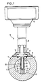
- the vortex flow meter 10 shown in FIG. 1 of the drawing has a measuring tube 11 shown in cross section, which is inserted into the pipeline through which the flow medium (liquid, gas) flows, the flow velocity of which is to be measured.
- the flow medium therefore flows in the representation of FIG. 1 perpendicular to the plane of the drawing through the flow channel 12 of the measuring tube 11.
- a flattened portion 13 is formed, from which a radial bore 14 into the interior of the Measuring tube is guided.
- a tubular housing support 15 is attached to the flattened portion 13 and carries a circuit housing 16 at the end opposite the measuring tube 11.
- a bluff body 20 is arranged, which extends diametrically over the entire diameter of the flow channel 12 and is firmly connected at both ends to the wall of the measuring tube 11.
- the bluff body 20 is designed in a manner known from vortex flow meters so that it generates Karman vortices in the flow medium.
- the bluff body 20 is a prismatic body of constant cross-section, which for example has the shape of an isosceles triangle, the base line of which faces the direction of flow. Two parallel vortex streets are created on the bluff body 20, the vertebrae of one vortex street being offset from the vortexes of the other vortex street.
- the measurement of the flow velocity is based on the fact that the distance between successive vortices in each vortex street is almost constant over a large range of flow velocities.
- the repetition frequency of the Kármán vortices is therefore proportional to the flow velocity.
- the vortex flow meter is therefore designed in such a way that it delivers a signal which is characteristic of the repetition frequency of the Kármán vortex.
- an axial cavity 21 is formed in the bluff body 20, which extends from the end of the bluff body lying at the top in FIG. 1 over the greater part of its length.
- the bluff body 20 is mounted in the measuring tube 11 so that the cavity 21 is coaxial with the bore 14.
- the cavity 21 is preferably cylindrical and has the same inner diameter as the bore 14. It is connected to the flow channel 12 of the measuring tube 11 via a plurality of passages which are guided through the bluff body 20 transversely to the direction of flow and are opposite one another in pairs.
- a first pair of passages 22, 23 lies approximately at the height of the axis of the flow channel 12, that is to say half the height of the bluff body 20.
- a second pair of passages 24, 25 lie at the upper end of the bluff body 20 directly on the wall of the measuring tube 11
- a third pair of passages 26, 27 are attached to the lower end of the cavity 21 at the level of the end wall 28 defining the cavity.
- a partition 29 of low height is formed on the end wall 28, which is parallel to the axis of the measuring tube 11.
- a swirl sensor 30 projects through the bore 14 into the cavity 21, where it extends almost to the partition 29.
- the vortex sensor 30 is supported by a flange 31 which is fastened to the flat 13 by means of screws 32.
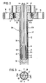
- the vortex sensor 30 is shown in more detail in the sectional view of FIG. 2. It consists of two components.
- the first component is a tubular sensor sleeve 33 which is connected to the flange 31 at one end and is sealed at the opposite end by an end wall 34.
- the flange 31 has one Center opening 35, which is coaxial to the sensor sleeve 33 and whose diameter is equal to the inner diameter of the sensor sleeve 33.
- the flange 31 has a plurality of holes 36 distributed around the circumference for the passage of the screws 32, with which it is fastened on the flat 13 (FIG. 1).
- the sensor sleeve 33 can be formed together with the end wall 34 in one piece with the flange 31 from the same material, for example from steel.
- the second component of the vortex sensor 30 is an electrode holder 40 which projects through the central opening 35 of the flange 31 into the interior of the sensor sleeve 33.
- the electrode holder 40 consists of a tube 41, which is connected to a second flange 42 and is preferably produced in one piece with the flange 42, for example likewise from steel.
- the flange 42 is fastened by means of screws 43 on the upper side of the flange 31, so that the electrode holder 34 projects through the central opening 35 into the interior of the sensor sleeve 33, where it extends up to the end wall 34.
- the tube 41 of the electrode holder 34 has three sections of different diameters.
- a first section 41a which sits in the central opening 35 of the flange 31, has an outer diameter which is equal to the diameter of the central opening 35, as a result of which a tight fit and a precise positioning of the electrode holder are ensured.
- the outer diameter of a second section 41b which makes up the largest part of the length of the electrode holder, is somewhat smaller than the inner diameter of the sensor sleeve 33, so that there is a narrow annular gap around the circumference between the section 41b and the sensor sleeve 33.
- the end section 41c of the tube 41 adjoins the middle section 41b via an inwardly projecting shoulder 44 and has one essential smaller diameter.
- This end section 41c carries an insulating sleeve 45, the outside diameter of which is somewhat smaller than the outside diameter of the middle section 41b.
- the insulating sleeve 45 can be made of ceramic, for example.
- two capacitor electrodes 46 and 47 are attached, which cover most of the circumferential surface and the lower end face of the insulating sleeve 45, but are mechanically and electrically separated from one another at two diametrically opposite locations by gaps 48, 49, like the lower end view of Fig. 3 shows.
- the capacitor electrodes 46, 47 can be formed by a metallization applied to the insulating sleeve 45 or by glued-on metal foils.
- the thicknesses of the insulating sleeve 45 and the capacitor electrodes 46, 47 are dimensioned such that an annular gap 50 of small gap width exists around the circumference between the capacitor electrodes 46, 47 and the inner surface of the sensor sleeve 33.
- Each capacitor electrode 46, 47 forms with the opposite section of the sensor sleeve 33, which acts as a counter electrode, a capacitor, the dielectric of which is air.
- the capacitance of each of these capacitors is proportional to the area of the capacitor electrode and inversely proportional to the gap width between the capacitor electrode and the sensor sleeve.
- the inner conductors of two shielded cables 51, 52 are soldered, which are guided through the hollow interior of the electrode holder 40 and through the tubular housing support 15 and the capacitor electrodes 46, 47 with connect the electronic evaluation circuit of the vortex flow meter housed in the circuit housing 16.
- the outer diameter of the sensor sleeve 33 of the swirl sensor 30 is somewhat smaller than the inner diameter of the cavity 21 in the bluff body 20, so that the sensor sleeve 33 is spaced on all sides from the wall of the cavity 21. There is thus a free space in the cavity 21 around the sensor sleeve 33, which is filled via the passages 22 to 27 with the flow medium flowing through the flow channel 12 of the measuring tube 11.
- the vortex sensor 30 is installed in the bluff body 20 so that the capacitor electrodes 46, 47 are symmetrical with respect to the axial center plane, which contains the axes of the measuring tube 11 and the bluff body 20 and is indicated in FIG. 3 by the line X-X.
- Each of the two components of the vortex sensor 30, namely the sensor sleeve 33 and the electrode holder 40, represents an elongated oscillating body which is held at one end and the free end of which is transversely to its longitudinal direction due to the action of external forces from the rest position shown in FIG. 2 can be deflected.
- the deflection consists in a bend, so that the sensor sleeve under the influence of the Vortex pressure fluctuations executes bending vibrations, the frequency of which is equal to the frequency of the pressure fluctuations.
- the bending vibration natural resonance frequency of the sensor sleeve 33 is very much higher than the highest occurring frequency of the vortex pressure fluctuations, so that the bending vibrations of the sensor sleeve 33 are excited subcritically and exactly follow the vortex pressure fluctuations according to frequency and phase.
- the amplitudes of the bending vibrations are very small, and the components of the vortex sensor 30 are designed and dimensioned such that the sensor sleeve 33 does not strike the wall of the cavity 21 or the electrode holder 40 when the vibration amplitudes are greatest.
- the upper passages 24, 25 and the lower passages 26, 27 in the bluff body 20 allow free circulation of the flow medium between the cavity 21 and the flow channel 12, so that the flow medium can dodge and follow the bending vibrations of the sensor sleeve 33 unhindered.
- the partition 29 between the lower passages 26 and 27 prevents direct pressure equalization around the lower end of the sensor sleeve.
- the electrode holder 40 arranged inside the tightly closed sensor sleeve 33 is not in contact with the flow medium and is therefore completely decoupled from its pressure fluctuations.
- the electrode holder 40 is therefore not caused to vibrate by the swirl pressure fluctuations, but remains at rest.
- the free end of the sensor sleeve 33 moves under the influence of the vortex pressure fluctuations relative to the fixed free end of the electrode holder, as indicated by the double arrow F in FIG. 2.
- the width of the air gap 50 between the electrodes 46, 47 and the opposite wall of the sensor sleeve 33 changes in opposite directions: If the The distance between the sensor sleeve 33 and the electrode 46 decreases, the distance between the sensor sleeve 33 and the electrode 47 increases at the same time, and vice versa. As a result, the capacitance values of the capacitors formed by the two electrodes 46, 47 and the sensor sleeve 33 also change in the opposite direction with the frequency of the vortex pressure fluctuations.
- the electronic evaluation circuit of the vortex flow meter housed in the circuit housing 16 can therefore generate an electrical signal based on these changes in capacitance which is characteristic of the frequency of the vortex pressure fluctuations and thus also of the flow velocity in the measuring tube 11.
- the two vibrating bodies can be jointly set into bending vibrations by such external forces.
- Such external forces can arise, in particular, from vibrations which set the measuring tube and thus the clamping point in a translatory oscillating movement in any axial direction or also try to rotate the two oscillating bodies about their clamping points.
- the free ends of the sensor sleeve 33 and the electrode holder 40 are deflected in the same direction by such external influences.
- the width of the gap 50 between the capacitor electrodes 46, 47 and the sensor sleeve 33 does not change noticeably in the case of these deflections in the same direction.
- Such external influences therefore do not cause a change in the two capacitances of the vortex sensor.
- there are also swirl pressure fluctuations at the same time as such external influences these cause an additional deflection of the sensor sleeve 33, that of the joint deflection of the two Vibrating body is superimposed and causes an opposite change in the two capacities.
- the vortex sensor described is therefore insensitive to vibrations in any direction of the axis or similar interference, but it enables reliable detection of the pressure fluctuations caused by Kármán's vortex even when such external interference is present.
- the electronic evaluation circuit is preferably designed in such a way that it generates a signal that depends on the difference between the two capacitances of the swirl sensor. Since the two capacitances change in opposite directions, the difference signal corresponds to twice the value of the capacitance change, while the base capacitances of the same size fall out of the difference signal. On the one hand, this enables a very precise and sensitive detection of the changes in capacity and, on the other hand, the elimination of the influence of further disturbance variables which can impair the function of the vortex flow meter. This applies in particular to the temperature and the static pressure of the flow medium.
- the vortex flow meter can be used under very different temperature and pressure conditions, and the temperature and pressure of the flow medium can also change within a wide range within the same area of application.
- Changes in the static pressure of the flow medium can change the cross section of the sensor sleeve due to deformation. This also changes the width of the air gap 50 and thus the value of the two basic capacities. Since, due to the symmetrical structure, such a cross-sectional change affects the two basic capacities in the same way, it is canceled out when the difference is formed, so that the differential signal is not influenced by changes in the static pressure.
- the described embodiment of the swirl sensor has a particularly good pressure resistance due to the cylindrical shape of the sensor sleeve and is therefore suitable for applications in which high pressures or large pressure fluctuations occur.
- Another cause of error in the signal evaluation can be that the shielded cables 51 and 52, via which the capacitor electrodes 46 and 47 are connected to the evaluation circuit, move relative to the electrode holder under the influence of vibrations or other interferences, so that from the Evaluation circuit variable interference capacities are detected.
- Such a relative movement of the cables can be prevented by a fixation, for example by means of a casting compound.
- the influence of interference capacities can also be active shielding of the cable can be switched off.
- the principle of active shielding is known to be that the potential of the shield is always tracked to the potential of the measuring electrode. In the upper area of the vortex sensor, such active shielding is definitely required to reduce the static capacitance and touch sensitivity.
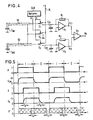
- Fig. 4 shows a capacitance measuring circuit which is particularly well suited as an input stage of the electronic evaluation circuit of the vortex flow meter described.
- This capacitance measuring circuit is designed according to the principle of "switched capacitors" known from DE-A-31 43 114. It enables a very sensitive and precise measurement of capacitance changes, even if they are very small 4 so that it enables active shielding in a very simple manner.
- the measuring capacitance C M1 being the capacitance that exists between the sensor sleeve 33 connected to ground and the capacitor electrode 46 connected to the evaluation circuit via the shielded cable 51.
- the measuring capacitance C M2 is the capacitance that exists between the sensor sleeve 33 connected to ground and the capacitor electrode 47 connected to the evaluation circuit via the shielded cable 52.
- the shields of the two cables 51 and 52 are indicated by dashed lines.
- the capacitance measuring circuit contains two completely identical circuit branches, each of which is assigned to one of the two measuring capacitors.
- the one with the measuring capacity C M1 the cable 51 connected circuit branch contains a switch S1, which in the one position, which is shown in Fig. 4, connects the inner conductor of the cable 51 to a terminal KL, which leads to a constant positive DC voltage + U, which, for example, the operating voltage the circuit is.
- the switch S 1 connects the measuring capacitance C M1 to a storage capacitor C 1, the capacitance of which is very large compared to the measuring capacitance C M1 .
- the inverting input of an operational amplifier A1 is also connected, the non-inverting input of which is connected to ground and the feedback circuit between the output and the inverting input contains a resistor R1.
- the circuit branch assigned to the measuring capacitance C M2 contains, in a corresponding manner, a changeover switch S2, a storage capacitor C02 and an operational amplifier A2 with a feedback resistor R2.
- the outputs of the two operational amplifiers A1 and A2 are connected to the two inputs of a differential amplifier A3.
- the two switches S1 and S2 are actuated by a control signal A, which is output at an output of a clock generator CLK.
- the clock CLK outputs a control signal B at a second output, which actuates a changeover switch S3, which puts the shields of the two cables 51 and 52 in one position to the voltage + U of the terminal KL and in the other position to ground.
- the diagram A shows the time course of the control signal A, which actuates the two switches S1 and S2.
- the control signal A periodically takes on two states 0 or 1, assuming that each changeover switch S 1, S 2 at the value 1 of the control signal A has the position shown in FIG. 4, in which it has the assigned measuring capacitance C M1 , C M2 the terminal KL connects while it disconnects the assigned measuring capacitance from the terminal KL at the value 0 of the control signal A and therefore connects it to the assigned storage capacitor C01 or C02.
- the diagram U CM of Fig. 5 shows the time course of the voltage at each measuring capacitance C M1, C M1 and thus also the voltage on the inner conductor of the associated cable 51 or 52. If you only consider the first circuit branch, then in each Phase I, which corresponds to the value 1 of the control signal A, the measuring capacitance C M1 charged to the voltage + U. Charging is not delay-free due to the inevitable time constant of the charging circuit, but the duration of phase 1 is dimensioned so large that the voltage U CM at the measuring capacitance C M1 certainly reaches the full value + U.
- phase II which corresponds to the value 0 of the control signal A
- the measuring capacitance C M1 discharges with the corresponding time constant into the storage capacitor C01. Since the capacitance of the storage capacitor C01 is very large against the measuring capacitance C M1 , the voltage across these two capacitances after the charge equalization is very small against the voltage + U.
- the duration of phase II which is preferably equal to the duration of phase I, is so large that the complete charge equalization can take place with certainty.
- the measuring capacitance C M1 is recharged to the voltage + U, while the charge of the storage capacitor C01 is slowly dissipated by the operational amplifier A1 acting as a current-voltage converter.
- the charge is equalized by a current which flows through the resistor R1 and causes the voltage across the storage capacitor C01 to be kept substantially at an average of zero.
- the current flowing through the resistor R 1 is equal to the mean value of the current which is discharged from the measuring capacitance C M1 .
- the output voltage of the operational amplifier A 1 assumes a value U C1 which is exactly proportional to the measuring capacitance C M1 .
- the output voltage of the operational amplifier A2 of the other circuit branch assumes a value U C2 , which is exactly proportional to the value of the measuring capacitance C M2 .
- the differential amplifier A3 forms the difference between the two voltages U C1 U C 2 and supplies a voltage U D at the output which is exactly proportional to the difference between the two measuring capacitances C M1 , C M2 .
- the capacitance of each of the two shielded cables 51, 52 is added to the measurement capacitance, and changes in the capacitance of the cable affect the measurement.
- active shielding is used in the capacitance measuring circuit of FIG. 4, in that the potential of the cable shield follows the potential on the shielded inner conductor of the cable. According to the prior art, such active shielding is achieved by continuously scanning the potential of the shielded line and applying it via an impedance converter the shield is placed.
- the active shielding is carried out in a particularly simple and effective manner with the aid of the switch S 3 actuated by the control signal B, without the need to return the potential of the shielded line.
- Diagram B of FIG. 5 shows the temporal course of control signal B, which periodically takes on the values 0 and 1 alternately with the same repetition frequency as control signal A.
- the diagram U K of FIG. 5 shows the time profile of the voltage on the shields of the two cables 51 and 52.
- control signals A and B are exactly in phase, the voltages U CM and U K also have essentially the same time profile. This fulfills the condition of active shielding that the potential of the shield constantly follows the potential of the shielded electrode. In Fig. 5, however, the control signals A and B are deliberately out of phase with each other to show that it is not important to maintain exact temporal relationships.
- the requirements for the timing of the control signal B in relation to the control signal A are therefore not critical. It is only necessary to adhere to the temporal conditions that the shielding voltage U K must have reached the voltage value + U before the start of each phase II and the voltage value 0 before the start of each phase I. Taking into account the recharging time T K, this means that the control signal B at the latest by the time period T K before the beginning of each phase II to the value 1 and at least the time period T K before the beginning of each phase I must be brought up to 0.
- the control signal B can have any values in the cross-hatched areas and only has to have the specified signal value in the areas of the duration T K marked with “1” or “0”.
- the switch S1, S2, S3 are shown in Fig. 4 only for clarity as a mechanical switch.
- these are very fast electronic switches, for example MOS field effect transistors. Since such electronic switches do not act as change-over switches, but as simple on-off switches, 4 must be replaced by two such electronic switches, which are driven in phase opposition by the control signal in question. To ensure that the two electronic switches are not open at the same time, it may then be expedient to insert short intervals between the successive switching phases, in which the two electronic switches, which together form a changeover switch, are blocked at the same time.
- the switch S3 can also be replaced by a threshold comparator, which receives the control signal A and outputs at its output, depending on the value of its input signal, either the voltage + U or the voltage 0. This further simplifies the circuit.
- the two components of the vortex sensor that are adjustable relative to one another that is to say the sensor sleeve 33 and the electrode holder 34, form a capacitive sensor acting as a mechano-electrical converter, which converts relative adjustments between the two components into changes in capacitance.
- the formation of two mutually changeable measuring capacitances with the aid of two capacitor electrodes results in the advantage that the capacitance measuring circuit can form a mean-free difference signal which only represents the changes in capacitance.
- this measure is by no means mandatory; the measurement of the frequency of the vortex pressure fluctuations is also possible if the electrode holder carries only one capacitor electrode and thus only one measuring capacity is available.
- the second circuit branch of the capacitance measuring circuit of FIG. 4 is simply omitted and the information about the flow rate is contained in the changes in the output voltage of the remaining circuit branch.
- the sensor sleeve 33 With regard to the compensation of vibrations and other disturbing influences as well as with regard to the sensitivity of the vortex flow meter, it is particularly advantageous to manufacture the sensor sleeve 33 from titanium.
- the modulus of elasticity of titanium is significantly smaller than the modulus of elasticity of steel; therefore, a sensor sleeve made of titanium experiences a much greater deflection under the influence of the vortex pressure fluctuations than a sensor sleeve of the same dimensions made of steel. Since the changes in capacitance are proportional to the deflection, the sensitivity of the swirl sensor is correspondingly greater.
- the ratio of density to modulus of elasticity in titanium is of the same order of magnitude as in steel, so that a vibrating body made of titanium exhibits a similar vibration behavior to a vibrating body made of steel.
- a sensor sleeve made of titanium can therefore be combined very well with an electrode holder made of steel in order to compensate for vibrations and other interferences.
- the advantageous properties of titanium in particular the very good corrosion resistance and the high fatigue strength, can be used in this way for the sensor sleeve.
Description
Die Erfindung bezieht sich auf einen Wirbelströmungsmesser zur Messung der Störmungsgeschwindigkeit eines Strömungsmediums in einer Rohrleitung, mit einem im Strömungskanal der Rohrleitung angeordneten Staukörper, der zur Erzeugung Kármán'scher Wirbel ausgebildet ist, einem Wirbelsensor, der auf die von den Kármán'schen Wirbeln erzeugten Druckschwankungen anspricht, wobei der Wirbelsensor einen ersten Schwingkörper aufweist, der durch die Wirbel-Druckschwankungen auslenkbar ist, sowie einen kapazitiven Wandler mit einem Elektrodenhalter, der in einem gegenüber dem Strömungsmedium abgeschlossenen Hohlraum des ersten Schwingkörpers angeordnet ist und wenigstens eine Kondensatorelektrode trägt, die einem Elektrodenabschnitt des ersten Schwingkörpers derart gegenüberliegt, daß sie mit diesem eine Meßkapazität bildet, die bei einer durch die Wirbel-Druckschwankungen verursachten Auslenkung des ersten Schwingkörpers veränderbar ist, wobei der Elektrodenhalter als zweiter Schwingkörper ausgebildet ist, der von den Wirbel-Druckschwankungen entkoppelt ist, und mit einer Auswerteschaltung, die eine mit der bzw. jeder Kondensatorelektrode verbundene Kapazitätsmeßschaltung enthält, die in Abhängigkeit von den Änderungen der bzw. jeder Meßkapazität ein für die Frequenz der Wirbel-Druckschwankungen und damit für die Strömungsgeschwindigkeit in der Rohrleitung kennzeichnendes elektrisches Signal erzeugt.The invention relates to a vortex flow meter for measuring the rate of disturbance of a flow medium in a pipeline, with a bluff body arranged in the flow channel of the pipeline, which is designed to generate Kármán vortices, a vortex sensor which acts on the pressure fluctuations generated by the Kármán vortices responds, wherein the vortex sensor has a first oscillating body, which can be deflected by the vortex pressure fluctuations, and a capacitive transducer with an electrode holder, which is arranged in a cavity of the first oscillating body which is sealed off from the flow medium and carries at least one capacitor electrode which corresponds to an electrode section of the lies opposite the first vibrating body in such a way that it forms a measuring capacity with it, which is caused by a deflection of the first one caused by the vortex pressure fluctuations Vibrating body is variable, the electrode holder being designed as a second vibrating body, which is decoupled from the swirl pressure fluctuations, and with an evaluation circuit which contains a capacitance measuring circuit connected to the or each capacitor electrode, which is dependent on the changes in the or each measuring capacitance an electrical signal characteristic of the frequency of the vortex pressure fluctuations and thus of the flow velocity in the pipeline is generated.
Bei einem aus der US-A-4 362 061 bekannten Wirbelströmungsmesser dieser Art bildet der Staukörper selbst den ersten Schwingkörper des Wirbelsensors. Der Staukörper enthält daher einen gegenüber dem Strömungsmedium dicht abgeschlossenen Hohlraum, in dem der Elektrodenhalter des kapazitiven Wandlers angeordnet ist. Der Staukörper ist durch einen Ansatz auf mehr als das Doppelte des Durchmessers des Strömungskanals verlängert und an beiden Enden so gelagert, daß er durch die Wirbel-Druckschwankungen in Biegeschwingungen versetzt wird. Durch die Schwingbewegung des Staukörpers relativ zu dem in seinem Hohlraum feststehenden Elektrodenhalter ergeben sich Kapazitätsänderungen zwischen den vom Elektrodenhalter getragenen Elektroden und den diesen Elektroden gegenüberliegenden Wandabschnitten des Staukörper-Hohlraums. Der Elektrodenhalter ist stabförmig und am einen Ende eingespannt, so daß er einen zweiten Schwingkörper bildet, der unter dem Einfluß äußerer Kräfte ebenfalls in Biegeschwingungen versetzt werden kann, durch die sein die Elektroden tragendes freies Ende ausgelenkt wird. Durch geeignete Bemessung des Schwingverhaltens von Staukörper und Elektrodenhalter soll erreicht werden, daß die Auslenkungen dieser beiden Schwingkörper auf der Höhe der Elektroden unter dem Einfluß von Vibrationen oder ähnlichen Störeinflüssen etwa gleich groß und gleich gerichtet sind, so daß solche Auslenkungen keine Kapazitätsänderungen zur Folge haben. Diese Bedingung läßt sich jedoch nur schwierig und unvollständig erfüllen, weil insbesondere die Ausbildung des ersten Schwingkörpers vorherrschend durch dessen Funktion als Staukörper bestimmt ist. Infolge des vorgegebenen Querschnitts und der erforderlichen Festigkeit des Staukörpers sind die durch die Wirbel-Druckschwankungen erzielbaren Schwingungsamplituden und demzufolge die dadurch verursachten Kapazitätsänderungen verhältnismäßig klein, was die Empfindlichkeit des Wirbelsensors beeinträchtigt. Ferner läßt sich das Schwingverhalten des Elektrodenhalters nicht gut an das Schwingverhalten des Staukörpers anpassen, so daß die Kompensation von Vibrationen und ähnlichen Störungen nur in unvollkommener Weise möglich ist. Auch ist es, insbesondere bei größeren Nennweiten des Strömungskanals, oft unerwünscht, daß der Staukörper selbst schwingt.In a vortex flow meter of this type known from US-A-4,362,061, the bluff body itself forms the first vibrating body of the vortex sensor. The bluff body therefore contains a cavity which is sealed off from the flow medium and in which the electrode holder of the capacitive transducer is arranged. The bluff body is extended by an approach to more than twice the diameter of the flow channel and supported at both ends so that it is caused by the vortex pressure fluctuations in bending vibrations. The oscillating movement of the bluff body relative to the electrode holder fixed in its cavity results in changes in capacitance between the electrodes carried by the electrode holder and the wall sections of the bluff body cavity opposite these electrodes. The electrode holder is rod-shaped and clamped at one end, so that it forms a second oscillating body which, under the influence of external forces, can also be set into bending vibrations by which its free end carrying the electrodes is deflected. By suitable dimensioning of the vibration behavior of the bluff body and the electrode holder, the aim is to ensure that the deflections of these two vibrating bodies at the height of the electrodes are approximately the same size and the same direction under the influence of vibrations or similar interfering influences, so that such deflections do not occur Result in changes in capacity. However, this condition can only be met with difficulty and incompletely, because in particular the formation of the first vibrating body is predominantly determined by its function as a bluff body. As a result of the predetermined cross section and the required strength of the bluff body, the vibration amplitudes that can be achieved by the swirl pressure fluctuations and consequently the changes in capacitance caused thereby are relatively small, which affects the sensitivity of the swirl sensor. Furthermore, the vibration behavior of the electrode holder cannot be adapted well to the vibration behavior of the bluff body, so that the compensation of vibrations and similar disturbances is only possible in an imperfect manner. It is also often undesirable, especially with larger nominal widths of the flow channel, for the bluff body to vibrate itself.
Aus der EP-A-0 110 321 ist es bekannt, den Staukörper eines Wirbelströmungsmessers im Strömungskanal feststehend zu montieren. Der Wirbelsensor dieses bekannten Wirbelströmungsmessers ist jedoch nicht mit einem kapazitiven, sondern mit einem piezoelektrischen Wandler ausgestattet. In dem Staukörper ist ein Hohlraum gebildet, der über Durchlässe mit dem Strömungskanal der Rohrleitung verbunden ist, und der piezoelektrische Wandler des Wirbelsensors ist mit einer in den Hohlraum des Staukörpers ragenden Druckempfangsplatte verbunden, die durch die in den Hohlraum übertragenen Wirbel-Druckschwankungen ausgelenkt wird. Die Auslenkungen der Druckempfangsplatte werden auf den piezoelektrischen Wandler übertragen und von diesem in elektrische Signale umgesetzt. Zur Kompensation von Vibrationen und ähnlichen Störeinflüssen ist ein zweiter piezoelektrischer Wandler gleicher Bauart außerhalb der Rohrleitung so angeordnet, daß er nur auf die Vibrationen und Störeinflüsse, jedoch nicht auf die Auslenkungen der Druckempfangsplatte anspricht. Dadurch ergibt sich eine beträchtliche Baulänge des Wirbelsensors, von dem ein großer Teil außerhalb der Rohrleitung liegt.From EP-A-0 110 321 it is known to mount the bluff body of a vortex flow meter in a fixed manner in the flow channel. The vortex sensor of this known vortex flow meter is not equipped with a capacitive, but with a piezoelectric transducer. A cavity is formed in the bluff body, which is connected via passages to the flow channel of the pipeline, and the piezoelectric transducer of the swirl sensor is connected to a pressure-receiving plate protruding into the cavity of the bluff body, which is deflected by the swirl pressure fluctuations transmitted into the cavity. The deflections of the pressure receiving plate are transmitted to the piezoelectric transducer and converted into electrical signals by the latter. To compensate for vibrations and similar interferences, a second piezoelectric transducer of the same type is arranged outside the pipeline in such a way that it responds only to the vibrations and interferences, but not to the deflections of the pressure-receiving plate. This results in a considerable length of the swirl sensor, a large part of which is outside the pipeline.
Die Kapazitätsmeßschaltung des in der US-A-4 362 061 beschriebenen Wirbelströmungsmessers enthält eine Brückenschaltung, die in zwei Brückenzweigen die beiden Kapazitäten enthält, die von zwei auf entgegengesetzten Seiten der beiden Schwingkörper angeordneten Elektrodenpaaren gebildet werden. An die eine Brückendiagonale wird eine Wechselspannung angelegt, so daß an der anderen Brückendiagonale eine Wechselspannung erhalten wird, die von der Differenz zwischen den beiden Kapazitäten abhängt. Da sich die beiden Kapazitäten infolge der Schwingbewegungen der beiden Schwingkörper gegensinnig ändern, ist die Brückenausgangs-Wechselspannung mit der Frequenz der Wirbeldruckschwankungen amplitudenmoduliert.The capacitance measuring circuit of the vortex flow meter described in US-A-4 362 061 contains a bridge circuit which contains the two capacitances in two bridge branches which are formed by two pairs of electrodes arranged on opposite sides of the two oscillating bodies. An AC voltage is applied to one bridge diagonal, so that an AC voltage is obtained on the other bridge diagonal, which depends on the difference between the two capacitances. Since the two capacitances change in opposite directions as a result of the oscillating movements of the two oscillating bodies, the bridge output AC voltage is amplitude-modulated with the frequency of the swirl pressure fluctuations.
Aus der DE-A-31 43 114 ist eine Kapazitätsmeßschaltung bekannt, die nach dem Prinzip der "geschalteten Kondensatoren" ("switched capacitors") arbeitet. Diese Kapazitätsmeßschaltung enthält für jede Meßkapazität eine Umschaltanordnung, welche die Meßkapazität mit einer vorgegebenen Umschaltfrequenz periodisch abwechselnd zur Aufladung an eine konstante Spannung legt und zur Entladung mit einem Speicherkondensator verbindet, dessen Kapazität groß gegen die Meßkapazität ist und dessen Klemmenspannung durch einen kontrollierten Entladestrom im wesentlichen auf einem konstanten Bezugspotential gehalten wird. Die Kapazitätsmessung beruht auf der Messung des mittleren Entladestroms der periodisch abwechselnd auf eine konstante Spannung aufgeladenen und entladenen Meßkapazität. Gewöhnlich wird der mittlere Entladestrom durch einen Strom-Spannungs-Wandler in eine Spannung umgesetzt, die der Meßkapazität proportional ist. Durch Verwendung von zwei nach dem gleichen Prinzip arbeitenden Schaltungszweigen ist es insbesondere möglich, Kapazitätsdifferenzen zwischen zwei Meßkapazitäten mit großer Empfindlichkeit und Genauigkeit zu messen, selbst wenn die Kapazitätsdifferenzen sehr klein gegen die Meßkapazitäten sind.From DE-A-31 43 114 a capacitance measuring circuit is known which works on the principle of "switched capacitors". This capacitance measuring circuit contains a switching arrangement for each measuring capacitance, which applies the measuring capacitance with a predetermined switching frequency periodically alternately for charging to a constant voltage and connects for discharging with a storage capacitor, the capacitance of which is large compared to the measuring capacitance and the terminal voltage of which is essentially due to a controlled discharge current is kept at a constant reference potential. The capacitance measurement is based on the measurement of the average discharge current of the measurement capacitance which is periodically alternately charged and discharged to a constant voltage. The average discharge current is usually converted by a current-voltage converter into a voltage which is proportional to the measuring capacity. By using two circuit branches operating on the same principle, it is in particular possible to measure capacitance differences between two measuring capacitances with great sensitivity and accuracy, even if the capacitance differences are very small compared to the measuring capacitances.
Unabhängig von der Art der verwendeten Kapazitätsmeßschaltung besteht bei Wirbelströmungsmessern mit kapazitiven Wirbelsensoren eine Fehlerursache bei der Signalauswertung in dem Einfluß von Streukapazitäten und Störfeldern. Dieser Einfluß kann durch die Verwendung von Kabeln mit geerdeter Abschirmung nicht vollständig ausgeschaltet werden. Solche abgeschirmten Kabel können sogar ihrerseits veränderliche Störkapazitäten verursachen, wenn sie sich unter dem Einfluß der Vibrationen relativ zu dem Elektrodenhalter bewegen. Es ist bekannt, den Einfluß von Streukapazitäten und Störfeldern durch eine aktive Schirmung auszuschalten. Das Prinzip der aktiven Schirmung besteht darin, daß das Potential der Abschirmung stets dem Potential der abgeschirmten Elektrode nachgeführt wird. Nach dem Stand der Technik erfolgt die aktive Schirmung dadurch, daß das Potential der abgeschirmten Elektrode abgetastet und über einen Impedanzwandler an die Abschirmung angelegt wird. Diese Lösung ist aufwendig, weil als Impedanzwandler ein Operationsverstärker benötigt wird, der hohen Anforderungen an Geschwindigkeit und Eingangskapazität genügen muß.Regardless of the type of capacitance measurement circuit used, in vortex flow meters with capacitive vortex sensors, the cause of the error in the signal evaluation is the influence of stray capacitances and interference fields. This influence cannot be completely eliminated by using cables with grounded shielding. Such shielded cables can in turn cause variable interference capacities if they move relative to the electrode holder under the influence of the vibrations. It is known to eliminate the influence of stray capacities and interference fields by active shielding. The principle of active shielding is that the potential of the shield always follows the potential of the shielded electrode. According to the prior art, active shielding is carried out by sensing the potential of the shielded electrode and applying it to the shield via an impedance converter. This solution is complex because an operational amplifier is required as an impedance converter, which must meet high demands on speed and input capacity.
Aufgabe der Erfindung ist die Schaffung eines Wirbelströmungsmessers der eingangs angegebenen Art, der bei sehr kleiner Bauhöhe eine optimale Kompensation von Vibrationen und ähnlichen mechanischen Störeinflüssen ergibt, ohne daß die Funktion des Staukörpers beeinträchtigt wird, und bei welchem der Einfluß von Streukapazitäten und Störfeldern auf das Meßergebnis mit geringem Aufwand wirksam ausgeschaltet ist.The object of the invention is to provide a vortex flow meter of the type mentioned, which results in an optimal compensation of vibrations and similar mechanical disturbances at a very small height without the function of the bluff body being impaired, and in which the influence of stray capacities and interference fields on the measurement result is effectively turned off with little effort.
Nach der Erfindung wird diese Aufgabe dadurch gelöst, daß in dem Staukörper ein Hohlraum gebildet ist, der über Durchlässe mit dem Strömungskanal der Rohrleitung in Verbindung steht, daß der erste Schwingkörper eine den Elektrodenhalter umgebende Sensorhülse ist, die in dem Hohlraum des Staukörpers angeordnet ist, daß die bzw. jede Kondensatorelektrode durch ein abgeschirmtes Kabel mit der Kapazitätsmeßschaltung verbunden ist, daß die Kapazitätsmeßschaltung für jede Meßkapazität eine Umschaltanordnung enthält, welche die Meßkapazität mit einer vorgegebenen Umschaltfrequenz periodisch abwechselnd zur Aufladung an eine konstante Spannung legt und zur Entladung mit einem Speicherkondensator verbindet, dessen Kapazität groß gegen die Meßkapazität ist und dessen Klemmenspannung durch einen kontrollierten Entladestrom im wesentlichen auf einem konstanten Bezugspotential gehalten wird, wobei die Größe des Entladestroms der Meßkapazität proportional ist und den Meßwert darstellt, und daß eine weitere Umschaltanordnung vorgesehen ist, welche die Kabelabschirmung mit der Umschaltfrequenz periodisch abwechselnd an die konstante Spannung und an das Bezugspotential legt.According to the invention, this object is achieved in that a cavity is formed in the bluff body, which is connected via passages to the flow channel of the pipeline, that the first vibrating body is a sensor sleeve surrounding the electrode holder, which is arranged in the cavity of the bluff body, that the or each capacitor electrode is connected to the capacitance measuring circuit by a shielded cable, that the capacitance measuring circuit contains a switching arrangement for each measuring capacitance, which alternately applies the measuring capacitance to a constant voltage alternately for charging at a predetermined switching frequency and connects it to a storage capacitor for discharging, the capacitance of which is large compared to the measuring capacitance is and its terminal voltage is maintained at a constant reference potential by a controlled discharge current, the size of the discharge current being proportional to the measuring capacitance and representing the measured value, and that a further switching arrangement is provided which periodically alternates the cable shield with the switching frequency to the constant Voltage and to the reference potential.
Bei dem Wirbelströmungsmesser nach der Erfindung sind die beiden Schwingkörper des Wirbelsensors von dem Staukörper unabhängig. Der Staukörper kann daher starr und unbeweglich ausgebildet und montiert sein. Die Sensorhülse, die den ersten Schwingkörper des Wirbelsensors bildet, kann ausschließlich im Hinblick auf das erwünschte Schwingverhalten ausgebildet sein. Insbesondere kann die Sensorhülse so ausgebildet werden, daß sie auf die Wirbel-Druckschwankungen mit Biegeschwingungen großer Amplitude reagiert, wodurch der Wirbelsensor eine große Empfindlichkeit aufweist. Ferner können die Sensorhülse und der Elektrodenhalter als gleichartige Schwingkörper mit gleichem Schwingverhalten ausgebildet sein, beispielsweise als am einen Ende eingespannte Biegeschwinger, deren freie Enden die Kondensatorelektroden tragen. Sie verhalten sich dann unter der Einwirkung von Vibrationen oder ähnlichen Störeinflüssen in völlig gleicher Weise, so daß diese Störungen optimal kompensiert werden. Insbesondere ergibt die erfindungsgemäße Ausbildung des Wirbelströmungsmessers auch eine sehr kleine Bauhöhe, da der Staukörper mit dem in seiner Ausnehmung angeordneten Wirbelsensor nicht länger als der Durchmesser des Strömungskanals zu sein braucht.In the vortex flow meter according to the invention, the two vibrating bodies of the vortex sensor are independent of the bluff body. The bluff body can therefore be rigid and immovable and assembled. The sensor sleeve, which forms the first oscillating body of the swirl sensor, can be designed exclusively with regard to the desired oscillating behavior. In particular, the sensor sleeve can be designed such that it reacts to the swirl pressure fluctuations with bending vibrations of large amplitude, as a result of which the swirl sensor has a high sensitivity. Furthermore, the sensor sleeve and the electrode holder can be designed as vibration bodies of the same type with the same vibration behavior, for example as a bending vibrator clamped at one end, the free ends of which carry the capacitor electrodes. They then behave in the same way under the influence of vibrations or similar disturbing influences, so that these disturbances are optimally compensated for. In particular, the inventive design of the vortex flow meter also results in a very small overall height, since the bluff body with the vortex sensor arranged in its recess need not be longer than the diameter of the flow channel.
Die Verwendung einer nach dem Prinzip der geschalteten Kondensatoren arbeitenden Kapazitätsmeßschaltung trägt gleichfalls zur Erzielung einer großen Empfindlichkeit bei. Vor allem aber ermöglicht die verwendete Kapazitätsmeßschaltung eine sehr wirksame aktive Schirmung mit sehr geringem zusätzlichem Aufwand. Hierfür wird die Tatsache ausgenutzt, daß das Potential der abzuschirmenden Elektrode nur zwei abwechselnde Werte annimmt, nämlich entweder das Bezugspotential oder das Potential der konstanten Spannung, auf die die Meßkapazität aufgeladen wird. Daher wird auf eine Abtastung und Rückführung des abzuschirmenden Potentials verzichtet; statt dessen werden einfach im Takt der Umschaltfrequenz abwechselnd die beiden Potentialwerte an die Abschirmung angelegt. Hierfür genügt eine weitere Umschaltanordnung einfacher Art. Als besonderer Vorteil erweist es sich, daß keine engen Zeittoleranzen für die Ansteuerung und Ansprechgeschwindigkeit der weiteren Umschaltanordnung bestehen, denn infolge des Prinzips der geschalteten Kondensatoren führen selbst erhebliche Zeitverschiebungen zwischen den Potentialänderungen der abgeschirmten Elektrode einerseits und der Abschirmung andererseits nicht zu Meßfehlern.The use of a capacitance measuring circuit operating on the principle of switched capacitors also contributes to achieving a high sensitivity. Above all, the capacitance measurement circuit used enables a very effective active shielding with very little additional effort. For this purpose, the fact is used that the potential of the electrode to be shielded only takes on two alternating values, namely either the reference potential or the potential of the constant voltage to which the measuring capacitance is charged. Sampling and feedback of the potential to be shielded is therefore dispensed with; instead, the two potential values are alternately applied to the shield in alternation with the switching frequency. A further changeover arrangement of a simple type is sufficient for this. A particular advantage is that there are no narrow time tolerances for the activation and response speed of the further changeover arrangement, because, owing to the principle of the switched capacitors, even considerable time shifts lead between the potential changes of the shielded electrode on the one hand and the shielding on the other hand, not to measurement errors.
Ein Ausführungsbeispiel der Erfindung ist in der Zeichnung dargestellt. In der Zeichnung zeigt:
- Fig. 1
- eine Schnittansicht einer Ausführungsform des Wirbelströmungsmessers nach der Erfindung,
- Fig. 2
- eine Schnittansicht des Wirbelsensors des Wirbelströmungsmessers von Fig. 1,
- Fig. 3
- eine Stirnansicht des Elektrodenhalters des Wirbelsensors von Fig. 2,
- Fig. 4
- die Kapazitätsmeßschaltung des Wirbelströmungsmessers und
- Fig. 5
- Zeitdiagramme zur Erläuterung der Funktionsweise der Kapazitätsmeßschaltung von Fig. 4.
- Fig. 1
- 2 shows a sectional view of an embodiment of the vortex flow meter according to the invention,
- Fig. 2
- 2 shows a sectional view of the vortex sensor of the vortex flow meter from FIG. 1,
- Fig. 3
- 3 shows an end view of the electrode holder of the vortex sensor from FIG. 2,
- Fig. 4
- the capacitance measuring circuit of the vortex flow meter and
- Fig. 5
- 4 is a timing diagram for explaining the operation of the capacitance measuring circuit of FIG. 4.
Der in Fig. 1 der Zeichnung dargestellte Wirbelströmungsmesser 10 hat ein im Querschnitt dargestelltes Meßrohr 11, das in die Rohrleitung eingefügt wird, durch die das Strömungsmedium (Flüssigkeit, Gas) fließt, dessen Strömungsgeschwindigkeit gemessen werden soll. Das Strömungsmedium fließt also in der Darstellung von Fig. 1 senkrecht zur Zeichenebene durch den Strömungskanal 12 des Meßrohres 11. An der in Fig. 1 oben liegenden Seite des Meßrohres 11 ist eine Abflachung 13 gebildet, von der eine radiale Bohrung 14 in das Innere des Meßrohres geführt ist. Auf der Abflachung 13 ist eine rohrförmige Gehäusestütze 15 befestigt, die an dem dem Meßrohr 11 entgegengesetzten Ende ein Schaltungsgehäuse 16 trägt.The
Im Innern des Meßrohres 11 ist ein Staukörper 20 angeordnet, der sich diametral über den ganzen Durchmesser des Strömungskanals 12 erstreckt und an beiden Enden fest mit der Wand des Meßrohres 11 verbunden ist. Der Staukörper 20 ist in einer bei Wirbelströmungsmessern bekannten Weise so ausgebildet, daß er in dem Strömungsmedium Kármán'sche Wirbel erzeugt. Der Staukörper 20 ist ein prismatischer Körper von gleichbleibendem Querschnitt, der beispielsweise die Form eines gleichschenkligen Dreiecks hat, dessen Grundlinie der Strömungsrichtung zugewandt ist. An dem Staukörper 20 entstehen zwei parallele Wirbelstraßen, wobei die Wirbel der einen Wirbelstraße gegen die Wirbel der anderen Wirbelstraße versetzt sind. Die Messung der Strömungsgeschwindigkeit beruht darauf, daß der Abstand zwischen aufeinanderfolgenden Wirbeln in jeder Wirbelstraße über einen großen Bereich von Strömungsgeschwindigkeiten nahezu konstant ist. Die Folgefrequenz der Kármán'schen Wirbel ist somit der Strömungsgeschwindigkeit proportional. Der Wirbelströmungsmesser ist daher so ausgebildet, daß er ein Signal liefert, das für die Folgefrequenz der Kármán'schen Wirbel kennzeichnend ist.In the interior of the measuring
Zu diesem Zweck ist in dem Staukörper 20 ein axialer Hohlraum 21 ausgebildet, der sich von dem in Fig. 1 oben liegenden Ende des Staukörpers über den größeren Teil von dessen Länge erstreckt. Der Staukörper 20 ist so im Meßrohr 11 montiert, daß der Hohlraum 21 koaxial zu der Bohrung 14 liegt. Der Hohlraum 21 ist vorzugsweise zylindrisch und hat den gleichen Innendurchmesser wie die Bohrung 14. Er steht mit dem Strömungskanal 12 des Meßrohres 11 über mehrere Durchlässe in Verbindung, die quer zur Strömungsrichtung durch den Staukörper 20 geführt sind und einander paarweise gegenüberliegen. Ein erstes Paar von Durchlässen 22, 23 liegt etwa auf der Höhe der Achse des Strömungskanals 12, also auf der halben Höhe des Staukörpers 20. Ein zweites Paar von Durchlässen 24, 25 liegt am oberen Ende des Staukörpers 20 unmittelbar an der Wand des Meßrohres 11. Ein drittes Paar von Durchlässen 26, 27 ist am unteren Ende des Hohlraums 21 auf der Höhe der den Hohlraum begrenzenden Stirnwand 28 angebracht. In der Mitte zwischen den beiden unteren Durchlässen 26 und 27 ist an der Stirnwand 28 eine Trennwand 29 geringer Höhe ausgebildet, die parallel zur Achse des MeßBrohres 11 liegt.For this purpose, an
Ein Wirbelsensor 30 ragt durch die Bohrung 14 in den Hohlraum 21, wo er sich fast bis zu der Trennwand 29 erstreckt. Der Wirbelsensor 30 wird von einem Flansch 31 getragen, der mittels Schrauben 32 auf der Abflachung 13 befestigt ist.A
Der Wirbelsensor 30 ist in der Schnittansicht von Fig. 2 in näheren Einzelheiten dargestellt. Er besteht aus zwei Bauteilen. Das erste Bauteil ist eine rohrförmige Sensorhülse 33, die am einen Ende mit dem Flansch 31 verbunden ist und an dem entgegengesetzten Ende durch eine Stirnwand 34 dicht verschlossen ist. Der Flansch 31 hat eine Mittelöffnung 35, die koaxial zu der Sensorhülse 33 liegt und deren Durchmesser gleich dem Innendurchmesser der Sensorhülse 33 ist. Ferner hat der Flansch 31 mehrere um den Umfang verteilte Bohrungen 36 für die Durchführung der Schrauben 32, mit denen er auf der Abflachung 13 (Fig. 1) befestigt wird. Die Sensorhülse 33 kann zusammen mit der Stirnwand 34 in einem Stück mit dem Flansch 31 aus dem gleichen Material geformt sein, beispielsweise aus Stahl.The
Das zweite Bauteil des Wirbelsensors 30 ist ein Elektrodenhalter 40, der durch die Mittelöffnung 35 des Flansches 31 in das Innere der Sensorhülse 33 ragt. Der Elektrodenhalter 40 besteht aus einem Rohr 41, das mit einem zweiten Flansch 42 verbunden ist und vorzugsweise in einem Stück mit dem Flansch 42 hergestellt ist, beispielsweise gleichfalls aus Stahl. Der Flansch 42 ist mittels Schrauben 43 auf der Oberseite des Flansches 31 befestigt, so daß der Elektrodenhalter 34 durch die Mittelöffnung 35 in das Innere der Sensorhülse 33 ragt, wo er sich bis nahe zu der Stirnwand 34 erstreckt.The second component of the
Das Rohr 41 des Elektrodenhalters 34 hat drei Abschnitte unterschiedlichen Durchmessers. Ein erster Abschnitt 41a, der in der Mittelöffnung 35 des Flansches 31 sitzt, hat einen Außendurchmesser, der gleich dem Durchmesser der Mittelöffnung 35 ist, wodurch ein fester Sitz und eine genaue Positionierung des Elektrodenhalters gewährleistet sind. Der Außendurchmesser eines zweiten Abschnitts 41b, der den größten Teil der Länge des Elektrodenhalters ausmacht, ist etwas kleiner als der Innendurchmesser der Sensorhülse 33, so daß rings um den Umfang ein schmaler ringförmiger Spalt zwischen dem Abschnitt 41b und der Sensorhülse 33 besteht. Der Endabschnitt 41c des Rohres 41 schließt sich über eine nach innen einspringende Schulter 44 an den mittleren Abschnitt 41b an und hat einen wesentlich kleineren Durchmesser. Dieser Endabschnitt 41c trägt eine Isolierhülse 45, deren Außendurchmesser etwas kleiner als der Außendurchmesser des mittleren Abschnitts 41b ist. Die Isolierhülse 45 kann beispielsweise aus Keramik bestehen. Auf der Isolierhülse 45 sind zwei Kondensatorelektroden 46 und 47 angebracht, die den größten Teil der Umfangsfläche und der unteren Stirnfläche der Isolierhülse 45 bedecken, aber an zwei einander diametral gegenüberliegenden Stellen durch Spalte 48, 49 mechanisch und elektrisch voneinander getrennt sind, wie die untere Stirnansicht von Fig. 3 zeigt. Die Kondensatorelektroden 46, 47 können durch eine auf die Isolierhülse 45 aufgebrachte Metallisierung oder aus aufgeklebten Metallfolien gebildet sein. Die Dicken der Isolierhülse 45 und der Kondensatorelektroden 46, 47 sind so bemessen, daß zwischen den Kondensatorelektroden 46, 47 und der Innenfläche der Sensorhülse 33 rings um den Umfang ein ringförmiger Spalt 50 von geringer Spaltbreite besteht.The
Jede Kondensatorelektrode 46, 47 bildet mit dem gegenüberliegenden, als Gegenelektrode wirkenden Abschnitt der Sensorhülse 33 einen Kondensator, dessen Dielektrikum Luft ist. Die Kapazität jedes dieser Kondensatoren ist zu der Flächenausdehnung der Kondensatorelektrode proportional und zu der Spaltbreite zwischen der Kondensatorelektrode und der Sensorhülse umgekehrt proportional.Each
An den die untere Stirnfläche der Isolierhülse 45 bedeckenden Abschnitten der Kondensatorelektroden 46 und 47 sind die Innenleiter von zwei abgeschirmten Kabeln 51, 52 angelötet, die durch das hohle Innere des Elektrodenhalters 40 und durch die rohrförmige Gehäusestütze 15 geführt sind und die Kondensatorelektroden 46, 47 mit der im Schaltungsgehäuse 16 untergebrachten elektronischen Auswerteschaltung des Wirbelströmungsmessers verbinden.On the sections of the
Wie Fig. 1 zeigt, ist der Außendurchmesser der Sensorhülse 33 des Wirbelsensors 30 etwas kleiner als der Innendurchmesser des Hohlraums 21 im Staukörper 20, so daß die Sensorhülse 33 allseitig im Abstand von der Wand des Hohlraums 21 liegt. Es besteht somit in dem Hohlraum 21 rings um die Sensorhülse 33 ein freier Raum, der über die Durchlässe 22 bis 27 mit dem Strömungsmedium gefüllt ist, das durch den Strömungskanal 12 des Meßrohres 11 fließt. Der Wirbelsensor 30 ist so in dem Staukörper 20 eingebaut, daß die Kondensatorelektroden 46, 47 symmetrisch in bezug auf die axiale Mittelebene liegen, die die Achsen des Meßrohres 11 und des Staukörpers 20 enthält und in Fig. 3 durch die Linie X-X angedeutet ist.1 shows, the outer diameter of the
Der beschriebene Aufbau des Wirbelströmungsmessers 10 ergibt die folgende Funktionsweise:The described structure of the
Jeder der beiden Bestandteile des Wirbelsensors 30, nämlich die Sensorhülse 33 und der Elektrodenhalter 40, stellt einen langgestreckten Schwingkörper dar, der am einen Ende gehalten ist und dessen freies Ende durch die Einwirkung äußerer Kräfte aus der in Fig. 2 dargestellten Ruhestellung quer zu seiner Längsrichtung ausgelenkt werden kann.Each of the two components of the
Wenn durch das Meßrohr 11 ein Strömungsmedium fließt und sich die beiden Kármán'schen Wirbelstraßen am Staukörper 20 bilden, entstehen zu beiden Seiten des Staukörpers gegenphasige periodische Druckschwankungen, die durch die Durchlässe 22 und 23 in den Hohlraum 21 übertragen werden und auf die Sensorhülse 33 einwirken. Unter dem Einfluß der von diesen Wirbel-Druckschwankungen ausgeübten Kräfte wird die Sensorhülse 33 quer zu ihrer Längsrichtung und quer zur Strömungsrichtung abwechselnd in entgegengesetzten Richtungen ausgelenkt. Da die Sensorhülse 33 am oberen Ende fest eingespannt ist, besteht die Auslenkung in einer Abbiegung, so daß die Sensorhülse unter der Einwirkung der Wirbel-Druckschwankungen Biegeschwingungen ausführt, deren Frequenz gleich der Frequenz der Druckschwankungen ist. Die Biegeschwingungs-Eigenresonanzfrequenz der Sensorhülse 33 ist sehr viel höher als die höchste vorkommende Frequenz der Wirbel-Druckschwankungen, so daß die Biegeschwingungen der Sensorhülse 33 unterkritisch angeregt werden und nach Frequenz und Phase genau den Wirbel-Druckschwankungen folgen. Die Amplituden der Biegeschwingungen sind sehr klein, und die Bestandteile des Wirbelsensors 30 sind so ausgebildet und bemessen, daß die Sensorhülse 33 bei den größten vorkommenden Schwingungsamplituden weder an der Wand des Hohlraums 21 noch am Elektrodenhalter 40 anschlägt.If a flow medium flows through the measuring
Die oberen Durchlässe 24, 25 und die unteren Durchlässe 26, 27 im Staukörper 20 erlauben eine freie Zirkulation des Strömungsmediums zwischen dem Hohlraum 21 und dem Strömungskanal 12, so daß das Strömungsmedium ungehindert den Biegeschwingungen der Sensorhülse 33 ausweichen und folgen kann. Die Trennwand 29 zwischen den unteren Durchlässen 26 und 27 verhindert einen direkten Druckausgleich um das untere Ende der Sensorhülse herum.The
Der im Innern der dicht verschlossenen Sensorhülse 33 angeordnete Elektrodenhalter 40 steht mit dem Strömungsmedium nicht in Kontakt und ist daher von dessen Druckschwankungen vollständig entkoppelt. Der Elektrodenhalter 40 wird daher durch die Wirbel-Druckschwankungen nicht in Biegeschwingungen versetzt, sondern bleibt in Ruhe. Demzufolge bewegt sich das freie Ende der Sensorhülse 33 unter dem Einfluß der Wirbel-Druckschwankungen relativ zu dem feststehenden freien Ende des Elektrodenhalters, wie in Fig. 2 durch den Doppelpfeil F angedeutet ist. Bei dieser Relativbewegung verändert sich die Breite des Luftspalts 50 zwischen den Elektroden 46, 47 und der gegenüberliegenden Wand der Sensorhülse 33 gegensinnig: Wenn der Abstand zwischen der Sensorhülse 33 und der Elektrode 46 abnimmt, wird gleichzeitig der Abstand zwischen der Sensorhülse 33 und der Elektrode 47 größer, und umgekehrt. Demzufolge ändern sich auch die Kapazitätswerte der von den beiden Elektroden 46, 47 und der Sensorhülse 33 gebildeten Kondensatoren gegensinnig mit der Frequenz der Wirbel-Druckschwankungen. Die im Schaltungsgehäuse 16 untergebrachte elektronische Auswerteschaltung des Wirbelströmungsmessers kann daher aufgrund dieser Kapazitätsänderungen ein elektrisches Signal erzeugen, das für die Frequenz der Wirbel-Druckschwankungen und somit auch für die Strömungsgeschwindigkeit im Meßrohr 11 kennzeichnend ist.The
Wenn dagegen auf das System äußere Kräfte einwirken, die über die Einspannstellen auf die beiden Schwingkörper, nämlich die Sensorhülse 33 und den Elektrodenhalter 40 übertragen werden, können die beiden Schwingkörper durch solche äußeren Kräfte gemeinsam in Biegeschwingungen versetzt werden. Solche äußeren Kräfte können insbesondere durch Vibrationen entstehen, die das Meßrohr und damit die Einspannstelle in eine translatorische Schwingbewegung in irgendeiner Achsrichtung versetzen oder auch die beiden Schwingkörper um ihre Einspannstellen zu drehen suchen. Durch solche äußeren Einflüsse werden die freien Enden der Sensorhülse 33 und des Elektrodenhalters 40 gleichsinnig ausgelenkt. Durch geeignete Ausbildung und Bemessung dieser beiden Teile kann erreicht werden, daß sich bei diesen gleichsinnigen Auslenkungen die Breite des Spaltes 50 zwischen den Kondensatorelektroden 46, 47 und der Sensorhülse 33 nicht merklich ändert. Solche äußeren Einflüsse verursachen daher keine Änderung der beiden Kapazitäten des Wirbelsensors. Wenn dagegen gleichzeitig mit solchen äußeren Einflüssen auch Wirbel-Druckschwankungen vorhanden sind, verursachen diese eine zusätzliche Auslenkung der Sensorhülse 33, die der gemeinsamen Auslenkung der beiden Schwingkörper überlagert ist und eine gegensinnige Änderung der beiden Kapazitäten zur Folge hat. Der beschriebene Wirbelsensor ist daher unempfindlich gegen Vibrationen in beliebigen Achsrichtungen oder ähnliche Störeinflüsse, er ermöglicht aber eine sichere Detektion der von Kármán'schen Wirbeln verursachten Druckschwankungen auch beim Vorhandensein solcher äußerer Störeinflüsse.If, on the other hand, external forces act on the system and are transmitted to the two vibrating bodies, namely the
Die elektronische Auswerteschaltung ist vorzugsweise so ausgebildet, daß sie ein Signal erzeugt, das von der Differenz der beiden Kapazitäten des Wirbelsensors abhängt. Da sich die beiden Kapazitäten gegensinnig ändern, entspricht das Differenzsignal dem doppelten Wert der Kapazitätsänderung, während die gleich großen Grundkapazitäten aus dem Differenzsignal herausfallen. Dies ermöglicht einerseits eine sehr genaue und empfindliche Detektion der Kapazitätsänderungen und andererseits die Eliminierung des Einflusses weiterer Störgrößen, die die Funktion des Wirbelströmungsmessers beeinträchtigen können. Dies gilt insbesondere für die Temperatur und den statischen Druck des Strömungsmediums. Der Wirbelströmungsmesser kann unter sehr verschiedenen Temperatur- und Druckverhältnissen zum Einsatz kommen, und auch innerhalb des gleichen Einsatzgebietes können sich die Temperatur und der Druck des Strömungsmediums in weiten Bereichen ändern.The electronic evaluation circuit is preferably designed in such a way that it generates a signal that depends on the difference between the two capacitances of the swirl sensor. Since the two capacitances change in opposite directions, the difference signal corresponds to twice the value of the capacitance change, while the base capacitances of the same size fall out of the difference signal. On the one hand, this enables a very precise and sensitive detection of the changes in capacity and, on the other hand, the elimination of the influence of further disturbance variables which can impair the function of the vortex flow meter. This applies in particular to the temperature and the static pressure of the flow medium. The vortex flow meter can be used under very different temperature and pressure conditions, and the temperature and pressure of the flow medium can also change within a wide range within the same area of application.
Temperaturänderungen wirken sich infolge der Wärmeausdehnungskoeffizienten der für die verschiedenen Bestandteile verwendeten Materialien auf die Abmessungen der Bestandteile des Wirbelsensors aus. Wenn die Bestandteile gleiche Wärmeausdehnungskoeffizienten haben, ändern sich ihre Abmessungen im gleichen Verhältnis, so daß sich für die beiden Kapazitäten keine Änderungen ergeben. Bei unterschiedlichen Wärmeausdehnungskoeffizienten der Bestandteile haben unterschiedliche Längenänderungen der Sensorhülse und des Elektrodenhalters keinen Einfluß auf die beiden Kapazitäten. Unterschiedliche Durchmesseränderungen dieser Teile können zwar zu Änderungen der Grundkapazitäten führen, doch ist dies für die Signalauswertung ohne Bedeutung, weil die Grundkapazitäten bei der Bildung des Differenzsignals herausfallen; die allein erfaßte Kapazitätsdifferenz bleibt von temperaturbedingten Änderungen unbeeinflußt.Temperature changes affect the dimensions of the components of the vortex sensor due to the thermal expansion coefficients of the materials used for the various components. If the components have the same coefficient of thermal expansion, their dimensions change in the same ratio, so that there are no changes for the two capacities. With different coefficients of thermal expansion of the components, different changes in length of the sensor sleeve and the electrode holder have no influence on the two capacities. Different changes in the diameter of these parts can lead to changes in the basic capacitances, but this is irrelevant for the signal evaluation because the basic capacitances drop out when the difference signal is formed; the capacity difference alone recorded remains unaffected by temperature-related changes.
Änderungen des statischen Druckes des Strömungsmediums können den Querschnitt der Sensorhülse durch Verformung verändern. Dadurch ändert sich auch die Breite des Luftspalts 50 und somit der Wert der beiden Grundkapazitäten. Da sich wegen des symmetrischen Aufbaus eine solche Querschnittsänderung auf die gleiche Weise auf die beiden Grundkapazitäten auswirkt, hebt sie sich bei der Differenzbildung wieder auf, so daß das Differenzsignal von Änderungen des statischen Drucks nicht beeinflußt wird.Changes in the static pressure of the flow medium can change the cross section of the sensor sleeve due to deformation. This also changes the width of the
In diesem Zusammenhang ist hervorzuheben, daß das beschriebene Ausführungsbeispiel des Wirbelsensors wegen der zylindrischen Form der Sensorhülse eine besonders gute Druckfestigkeit aufweist und sich daher für Anwendungen eignet, bei denen hohe Drücke oder große Druckschwankungen auftreten.In this context it should be emphasized that the described embodiment of the swirl sensor has a particularly good pressure resistance due to the cylindrical shape of the sensor sleeve and is therefore suitable for applications in which high pressures or large pressure fluctuations occur.
Eine weitere Fehlerursache bei der Signalauswertung kann darin bestehen, daß sich die abgeschirmten Kabel 51 und 52, über welche die Kondensatorelektroden 46 und 47 mit der Auswerteschaltung verbunden sind, unter dem Einfluß von Vibrationen oder anderen Störeinflüssen relativ zu dem Elektrodenhalter bewegen, so daß von der Auswerteschaltung veränderliche Störkapazitäten erfaßt werden. Eine solche Relativbewegung der Kabel kann durch eine Fixierung verhindert werden, beispielsweise mittels einer Vergußmasse. Der Einfluß von Störkapazitäten kann jedoch auch durch eine aktive Schirmung des Kabels ausgeschaltet werden. Das Prinzip der aktiven Schirmung besteht bekanntlich darin, daß das Potential der Abschirmung stets dem Potential der Meßelektrode nachgeführt wird. Im oberen Bereich des Wirbelsensors ist eine solche aktive Schirmung zur Verringerung der statischen Kapazität und der Berührungsempfindlichkeit auf jeden Fall erforderlich.Another cause of error in the signal evaluation can be that the shielded
Fig. 4 zeigt eine Kapazitätsmeßschaltung, die sich besonders gut als Eingangsstufe der elektronischen Auswerteschaltung des beschriebenen Wirbelströmungsmessers eignet. Diese Kapazitätsmeßschaltung ist nach dem aus der DE-A- 31 43 114 bekannten Prinzip der "geschalteten Kondensatoren" (switched capacitors") ausgebildet. Sie ermöglicht eine sehr empfindliche und genaue Messung von Kapazitätsänderungen, auch wenn diese sehr klein sind. Zusätzlich ist die Kapazitätsmeßschaltung von Fig. 4 so ausgebildet, daß sie auf sehr einfache Weise eine aktive Schirmung ermöglicht.Fig. 4 shows a capacitance measuring circuit which is particularly well suited as an input stage of the electronic evaluation circuit of the vortex flow meter described. This capacitance measuring circuit is designed according to the principle of "switched capacitors" known from DE-A-31 43 114. It enables a very sensitive and precise measurement of capacitance changes, even if they are very small 4 so that it enables active shielding in a very simple manner.
Fig. 4 zeigt die beiden Meßkapazitäten CM1 und CM2 des Wirbelsensors 30, wobei die Meßkapazität CM1 die Kapazität ist, die zwischen der an Masse liegenden Sensorhülse 33 und der über das abgeschirmte Kabel 51 mit der Auswerteschaltung verbundenen Kondensatorelektrode 46 besteht. In entsprechender Weise ist die Meßkapazität CM2 die Kapazität, die zwischen der an Masse liegenden Sensorhülse 33 und der über das abgeschirmte Kabel 52 mit der Auswerteschaltung verbundenen Kondensatorelektrode 47 besteht. Die Abschirmungen der beiden Kabel 51 und 52 sind durch gestrichelte Linien angedeutet.4 shows the two measuring capacitances C M1 and C M2 of the
Die Kapazitätsmeßschaltung enthält zwei völlig gleiche Schaltungszweige, die jeweils einer der beiden Meßkapazitäten zugeordnet sind. Der mit der Meßkapazität CM1 über das Kabel 51 verbundene Schaltungszweig enthält einen Umschalter S₁, der in der einen Stellung, die in Fig. 4 gezeigt ist, den Innenleiter des Kabels 51 mit einer Klemme KL verbindet, die gegen Masse eine konstante positive Gleichspannung +U führt, die beispielsweise die Betriebsspannung der Schaltung ist. In der anderen Stellung verbindet der Umschalter S₁ die Meßkapazität CM1 mit einem Speicherkondensator C₀₁, dessen Kapazität sehr groß gegen die Meßkapazität CM1 ist. An die miteinander verbundenen Klemmen des Umschalters S₁ und des Speicherkondensators C₀₁ ist auch der invertierende Eingang eines Operationsverstärkers A₁ angeschlossen, dessen nichtinvertierender Eingang an Masse liegt und dessen Rückkopplungskreis zwischen dem Ausgang und dem invertierenden Eingang einen Widerstand R₁ enthält.The capacitance measuring circuit contains two completely identical circuit branches, each of which is assigned to one of the two measuring capacitors. The one with the measuring capacity C M1 the
Der der Meßkapazität CM2 zugeordnete Schaltungszweig enthält in entsprechender Weise einen Umschalter S₂ einen Speicherkondensator C₀₂ und einen Operationsverstärker A₂ mit einem Rückkopplungswiderstand R₂.The circuit branch assigned to the measuring capacitance C M2 contains, in a corresponding manner, a changeover switch S₂, a storage capacitor C₀₂ and an operational amplifier A₂ with a feedback resistor R₂.
Die Ausgänge der beiden Operationsverstärker A₁ und A₂ sind mit den beiden Eingängen eines Differenzverstärkers A₃ verbunden.The outputs of the two operational amplifiers A₁ and A₂ are connected to the two inputs of a differential amplifier A₃.
Die beiden Umschalter S₁ und S₂ werden durch ein Steuersignal A betätigt, das an einem Ausgang eines Taktgebers CLK abgegeben wird. Der Taktgeber CLK gibt an einem zweiten Ausgang ein Steuersignal B ab, das einen Umschalter S₃ betätigt, der die Abschirmungen der beiden Kabel 51 und 52 in der einen Stellung an die Spannung +U der Klemme KL und in der anderen Stellung an Masse legt.The two switches S₁ and S₂ are actuated by a control signal A, which is output at an output of a clock generator CLK. The clock CLK outputs a control signal B at a second output, which actuates a changeover switch S₃, which puts the shields of the two
Die Funktionsweise der Kapazitätsmeßschaltung von Fig. 4 soll anhand der Zeitdiagramme von Fig. 5 erläutert werden. Die Beschreibung des der Meßkapazität CM1 zugeordneten Schaltungszweigs gilt natürlich in gleicher Weise auch für den anderen Schaltungszweig.The operation of the capacitance measuring circuit of FIG. 4 will be explained on the basis of the time diagrams of FIG. 5. The description of the one assigned to the measuring capacitance C M1 Circuit branch naturally also applies in the same way to the other circuit branch.
Das Diagramm A zeigt den zeitlichen Verlauf des Steuersignals A, das die beiden Umschalter S₁ und S₂ betätigt. Das Steuersignal A nimmt periodisch abwechselnd zwei Zustände 0 oder 1 an, wobei angenommen wird, daß jeder Umschalter S₁, S₂ beim Wert 1 des Steuersignals A die in Fig. 4 gezeigte Stellung hat, in der er die zugeordnete Meßkapazität CM1, CM2 mit der Klemme KL verbindet, während er beim Wert 0 des Steuersignals A die zugeordnete Meßkapazität von der Klemme KL abtrennt und dafür mit dem zugeordneten Speicherkondensator C₀₁ bzw. C₀₂ verbindet.The diagram A shows the time course of the control signal A, which actuates the two switches S₁ and S₂. The control signal A periodically takes on two
Das Diagramm UCM von Fig. 5 zeigt den zeitlichen Verlauf der Spannung an jeder Meßkapazität CM1, CM1 und somit auch die Spannung auf dem Innenleiter des zugeordneten Kabels 51 bzw. 52. Wenn man nur den ersten Schaltungszweig betrachtet, so wird in jeder Phase I, die dem Wert 1 des Steuersignals A entspricht, die Meßkapazität CM1 auf die Spannung +U aufgeladen. Die Aufladung erfolgt wegen der unvermeidlichen Zeitkonstante des Ladekreises nicht verzögerungsfrei, doch ist die Dauer der Phase 1 so groß bemessen, daß die Spannung UCM an der Meßkapazität CM1 mit Sicherheit den vollen Wert +U erreicht.The diagram U CM of Fig. 5 shows the time course of the voltage at each measuring capacitance C M1, C M1 and thus also the voltage on the inner conductor of the associated
In der Phase II, die dem Wert 0 des Steuersignals A entspricht, entlädt sich die Meßkapazität CM1 mit der entsprechenden Zeitkonstante in den Speicherkondensator C₀₁. Da die Kapazität des Speicherkondensators C₀₁ sehr groß gegen die Meßkapazität CM1 ist, ist die Spannung an diesen beiden Kapazitäten nach dem Ladungsausgleich sehr klein gegen die Spannung +U. Die Dauer der Phase II, die vorzugsweise gleich der Dauer der Phase I ist, ist so groß bemessen, daß der vollständige Ladungsausgleich mit Sicherheit stattfinden kann.In phase II, which corresponds to the
In der folgenden Phase I wird die Meßkapazität CM1 wieder auf die Spannung +U aufgeladen, während die Ladung des Speicherkondensators C₀₁ durch den als Strom-Spannungs-Wandler wirkenden Operationsverstärker A₁ langsam abgeführt wird. Der Ladungsausgleich erfolgt durch einen Strom, der über den Widerstand R₁ fließt und bewirkt, daß die Spannung am Speicherkondensator C₀₁ im Mittel im wesentlichen auf dem Wert Null gehalten wird. Der über den Widerstand R₁ fließende Strom ist gleich dem Mittelwert des Stroms, der vom der Meßkapazität CM1 entladen wird. Für die Aufrechterhaltung dieses Stroms nimmt die Ausgangsspannung des Operationsverstärkers A₁ einen Wert UC1 an, der der Meßkapazität CM1 exakt proportional ist.In the following phase I, the measuring capacitance C M1 is recharged to the voltage + U, while the charge of the storage capacitor C₀₁ is slowly dissipated by the operational amplifier A₁ acting as a current-voltage converter. The charge is equalized by a current which flows through the resistor R₁ and causes the voltage across the storage capacitor C₀₁ to be kept substantially at an average of zero. The current flowing through the
In gleicher Weise nimmt die Ausgangsspannung des Operationsverstärkers A₂ des anderen Schaltungszweiges einen Wert UC2 an, der dem Wert der Meßkapazität CM2 exakt proportional ist.In the same way, the output voltage of the operational amplifier A₂ of the other circuit branch assumes a value U C2 , which is exactly proportional to the value of the measuring capacitance C M2 .
Der Differenzverstärker A₃ bildet die Differenz der beiden Spannungen UC1 UC2 und liefert am Ausgang eine Spannung UD, die der Differenz zwischen den beiden Meßkapazitäten CM1, CM2 exakt proportional ist.The differential amplifier A₃ forms the difference between the two voltages U C1 U C 2 and supplies a voltage U D at the output which is exactly proportional to the difference between the two measuring capacitances C M1 , C M2 .
Wenn keine besonderen Maßnahmen getroffen werden, addiert sich die Kapazität jedes der beiden abgeschirmten Kabel 51, 52 zu der Meßkapazität, und Kapazitätsänderungen des Kabels wirken sich auf die Messung aus. Zur Ausschaltung des Einflusses der Kabelkapazitäten wird bei der Kapazitätsmeßschaltung von Fig. 4 eine aktive Schirmung angewendet, indem das Potential der Kabelabschirmung dem Potential auf dem abgeschirmten Innenleiter des Kabels nachgeführt wird. Nach dem Stand der Technik erfolgt eine solche aktive Schirmung dadurch, daß das Potential der abgeschirmten Leitung dauernd abgetastet und über einen Impedanzwandler an die Abschirmung gelegt wird. Im Gegensatz dazu erfolgt bei der Kapazitätsmeßschaltung von Fig. 4 die aktive Schirmung auf besonders einfache und wirksame Weise mit Hilfe des vom Steuersignal B betätigten Umschalters S₃, ohne daß eine Rückführung des Potentials der abgeschirmten Leitung notwendig ist.If no special measures are taken, the capacitance of each of the two shielded
Das Diagramm B von Fig. 5 zeigt den zeitlichen Verlauf des Steuersignals B, das mit der gleichen Folgefrequenz wie das Steuersignal A periodisch abwechselnd die Werte 0 und 1 annimmt. Das Diagramm UK von Fig. 5 zeigt den zeitlichen Verlauf der Spannung an den Abschirmungen der beiden Kabel 51 und 52. Wenn das Steuersignal B den Wert 1 annimmt, werden die beiden Kabelabschirmungen an die Spannung +U gelegt, und die Spannung UK erreicht den Spannungswert +U nach einer durch die Zeitkonstante bedingten Umladezeit TK. Wenn das Steuersignal B den Wert 0 annimmt, werden die Kabelabschirmungen an Massepotential gelegt, und die Spannung UK erreicht den Spannungswert 0 wieder nach der Umladezeit TK.Diagram B of FIG. 5 shows the temporal course of control signal B, which periodically takes on the
Aus dem Diagramm von Fig. 5 ist folgendes zu erkennen: Wenn die Steuersignale A und B genau phasengleich sind, haben auch die Spannungen UCM und UK im wesentlichen den gleichen zeitlichen Verlauf. Damit ist die Bedingung der aktiven Schirmung erfüllt, daß das Potential der Abschirmung ständig dem Potential der abgeschirmten Elektrode folgt. In Fig. 5 sind aber die Steuersignale A und B absichtlich gegeneinander phasenverschoben dargestellt, um zu zeigen, daß es nicht auf die Einhaltung exakter zeitlicher Beziehungen ankommt. Es gibt dann zwar in jeder Phase II am Anfang einen Zeitabschnitt, in welchem sich die Meßkapazität CM1 bereits in den Speicherkondensator C₀₁ entlädt, während an der Kabelabschirmung noch die Spannung +U anliegt, so daß sich die Abschirmkapazität auflädt und die entsprechende Ladung in den Speicherkondensator C₀₁ fließt; wenn jedoch anschließend in der gleichen Phase II die Abschirmung an Masse gelegt wird, während der abgeschirmte Leiter noch mit dem Speicherkondensator C₀₁ verbunden ist, fließt die gleiche Ladung wieder vom Speicherkondensator C₀₁ in die Abschirmkapazität zurück. Diese Ladungsverschiebungen heben sich also im Mittel gegenseitig auf, so daß auf dem Speicherkondensator C₀₁ effektiv nur die zu erfassende Ladung der Meßkapazität CM1 verbleibt, die allein für den Strom über den Widerstand R₁ und damit für die Spannung UC1 am Ausgang des Operationsverstärkers A₁ maßgeblich ist.The following can be seen from the diagram in FIG. 5: If the control signals A and B are exactly in phase, the voltages U CM and U K also have essentially the same time profile. This fulfills the condition of active shielding that the potential of the shield constantly follows the potential of the shielded electrode. In Fig. 5, however, the control signals A and B are deliberately out of phase with each other to show that it is not important to maintain exact temporal relationships. There is then in each phase II at the beginning a period in which the measuring capacitance C M1 is already discharged into the storage capacitor C₀₁, while the voltage + U is still present on the cable shield, so that the shielding capacitance charges and the corresponding charge flows into the storage capacitor C₀₁; However, if the shield is then connected to ground in the same phase II while the shielded conductor is still connected to the storage capacitor C₀₁, the same charge flows back from the storage capacitor C₀₁ into the shielding capacitance. These charge shifts cancel each other out on average, so that effectively only the charge to be detected of the measuring capacitance C M1 remains on the storage capacitor C₀₁, which is decisive solely for the current through the resistor R₁ and thus for the voltage U C1 at the output of the operational amplifier A₁ is.
Die Anforderungen an die zeitliche Lage des Steuersignals B in bezug auf das Steuersignal A sind also unkritisch. Es sind nur die zeitlichen Bedingungen einzuhalten, daß die Abschirmspannung UK vor dem Beginn jeder Phase II den Spannungswert +U und vor dem Beginn jeder Phase I den Spannungswert 0 erreicht haben muß. Unter Berücksichtigung der Umladezeit TK bedeutet dies, daß das Steuersignal B spätestens um die Zeitspanne TK vor dem Beginn jeder Phase II auf den Wert 1 und spätestens um die Zeitspanne TK vor dem Beginn jeder Phase I auf den Wert 0 gebracht sein muß. Daraus ergeben sich die im Diagramm B'dargestellten zeitlichen Bedingungen: Das Steuersignal B kann in den kreuzschraffierten Bereichen beliebige Werte haben und muß nur in den mit "1" bzw. "0" markierten Bereichen der Dauer TK den angegebenen Signalwert haben.The requirements for the timing of the control signal B in relation to the control signal A are therefore not critical. It is only necessary to adhere to the temporal conditions that the shielding voltage U K must have reached the voltage value + U before the start of each phase II and the
Die Umschalter S₁, S₂, S₃ sind in Fig. 4 nur der Deutlichkeit wegen als mechanische Schalter dargestellt. In Wirklichkeit handelt es sich hierbei natürlich um sehr schnelle elektronische Schalter, beispielsweise MOS-Feldeffekttransistoren. Da solche elektronischen Schalter nicht als Umschalter, sondern als einfache Ein-Aus-Schalter wirken, muß jeder Umschalter von Fig. 4 durch zwei derartige elektronische Schalter ersetzt werden, die durch das betreffende Steuersignal gegenphasig angesteuert werden. Um sicherzustellen, daß nicht die beiden elektronischen Schalter gleichzeitig geöffnet sind, kann es dann zweckmäßig sein, zwischen die aufeinanderfolgenden Schaltphasen jeweils kurze Intervalle einzufügen, in denen die beiden elektronischen Schalter, die zusammen einen Umschalter bilden, gleichzeitig gesperrt sind.The switch S₁, S₂, S₃ are shown in Fig. 4 only for clarity as a mechanical switch. In reality, of course, these are very fast electronic switches, for example MOS field effect transistors. Since such electronic switches do not act as change-over switches, but as simple on-off switches, 4 must be replaced by two such electronic switches, which are driven in phase opposition by the control signal in question. To ensure that the two electronic switches are not open at the same time, it may then be expedient to insert short intervals between the successive switching phases, in which the two electronic switches, which together form a changeover switch, are blocked at the same time.
Der Umschalter S₃ kann auch durch einen Schwellenwert-Komparator ersetzt werden, der das Steuersignal A empfängt und an seinem Ausgang, je nach dem Wert seines Eingangssignals, entweder die Spannung +U oder die Spannung 0 abgibt. Dadurch ergibt sich eine weitere Vereinfachung der Schaltung.The switch S₃ can also be replaced by a threshold comparator, which receives the control signal A and outputs at its output, depending on the value of its input signal, either the voltage + U or the
Bei dem zuvor beschriebenen Wirbelströmungsmesser bilden die beiden relativ zueinander verstellbaren Bestandteile des Wirbelsensors, also die Sensorhülse 33 und der Elektrodenhalter 34, einen als mechano-elektrischen Wandler wirkenden kapazitiven Sensor, der relative Verstellungen zwischen den beiden Bestandteilen in Kapazitätsänderungen umsetzt. Die Bildung von zwei gegensinnig veränderbaren Meßkapazitäten mit Hilfe von zwei Kondensatorelektroden ergibt dabei den Vorteil, daß die Kapazitätsmeßschaltung ein mittelwertfreies Differenzsignal bilden kann, das nur die Kapazitätsänderungen darstellt. Diese Maßnahme ist aber keineswegs zwingend; die Messung der Frequenz der Wirbel-Druckschwankungen ist auch dann möglich, wenn der Elektrodenhalter nur eine Kondensatorelektrode trägt und somit nur eine Meßkapazität vorhanden ist. In diesem Fall entfällt einfach der zweite Schaltungszweig der Kapazitätsmeßschaltung von Fig. 4, und die Information über die Strömungsgeschwindigkeit ist in den Änderungen der Ausgangsspannung des verbliebenen Schaltungszweigs enthalten.In the vortex flow meter described above, the two components of the vortex sensor that are adjustable relative to one another, that is to say the
Die beschriebene Kompensation von Vibrationen und anderen Störeinflüssen tritt auch in diesem Fall in vollem Umfang ein.The described compensation of vibrations and other interferences also occurs in this case in full.
Sowohl hinsichtlich der Kompensation von Vibrationen und anderen Störeinflüssen als auch hinsichtlich der Empfindlichkeit des Wirbelströmungsmessers ist es besonders vorteilhaft, die Sensorhülse 33 aus Titan herzustellen. Der Elastizitätsmodul von Titan ist wesentlich kleiner als der Elastizitätsmodul von Stahl; daher erfährt eine Sensorhülse aus Titan unter dem Einfluß der Wirbel-Druckschwankungen eine wesentlich größere Auslenkung als eine Sensorhülse gleicher Abmessungen aus Stahl. Da die Kapazitätsänderungen der Auslenkung proportional sind, ist die Empfindlichkeit des Wirbelsensors entsprechend größer. Andererseits liegt bei Titan das Verhältnis von Dichte zum Elastizitätsmodul in der gleichen Größenordnung wie bei Stahl, so daß ein Schwingkörper aus Titan ein ähnliches Schwingverhalten wie ein Schwingkörper aus Stahl zeigt. Eine Sensorhülse aus Titan kann daher hinsichtlich der Kompensation von Vibrationen und anderen Störeinflüssen sehr gut mit einem Elektrodenhalter aus Stahl kombiniert werden. Ferner können auf diese Weise die vorteilhaften Eigenschaften von Titan, insbesondere die sehr gute Korosionsbeständigkeit und die hohe Dauerfestigkeit, für die Sensorhülse nutzbar gemacht werden.With regard to the compensation of vibrations and other disturbing influences as well as with regard to the sensitivity of the vortex flow meter, it is particularly advantageous to manufacture the
Claims (3)
- Vortex flow meter for measuring the flow velocity of a flow medium in a tube (11) comprising a bluff body (20) arranged in the flow passage (12) of said tube (11) for generating Kármán vortices, a vortex sensor (30) which responds to the pressure fluctuations generated by the Kármán vortices, said vortex sensor (30) having a first vibratory body (33) which is displaceable by said vortex pressure fluctuations, and a capacitive transducer having an electrode carrier (40) arranged in a cavity (21) of said first vibratory body (33) which is closed with respect to said flow medium, which electrode carrier carries at least one capacitor electrode (46, 47), disposed opposite one electrode portion of said first vibratory body (33) to form therewith a measured capacitance (CM1, CM2) variable upon displacement of said first vibratory body (33) due to the vortex pressure fluctuations, said electrode carrier (40) being formed as a second vibratory body decoupled from said vortex pressure fluctuations, and an evaluation circuit including a capacitance measuring circuit connected to said or to each capacitor electrode (46, 47), respectively, which capacitance measuring circuit in dependence on the variations of the or each measured capacitance (CM1, CM2), respectively, generates an electrical signal (UD) characteristic of the frequency of the vortex pressure fluctuations and thus of the flow velocity in said tube (11),
characterized in that a cavity (21) is formed in the bluff body (20) , said cavity communicating with the flow passage of said tube (11) via passages (22, 23, 24, 25, 26, 27), that said first vibratory body (33) is a sensor sleeve (33) surrounding said electrode carrier (40) and being disposed in said cavity (21) of said bluff body (20), that the or each capacitor electrode (46, 47) is connected to said capacitance measuring circuit by a shielded cable (51, 52), that said capacitance measuring circuit includes a switchover means (S₁, S₂) for each measuring capacitance (CM1, CM2) , which with a predetermined switchover frequency periodically and alternately connects said measured capacitance (CM1, CM2) for charging to a constant voltage (+U) and for discharging connects the same to a storage capacitor (C₀₁, C₀₂), whose capacitance is large compared with the measured capacitance and whose terminal voltage is held substantially at a constant reference potential by a controlled discharge current, the magnitude of the discharge current being proportional to said measured capacitance and representing the measured value, and that a further switchover means (S₃) is provided which with the switchover frequency periodically and alternately connects said shielded cable to said constant voltage (+U) and to said reference potential, respectively. - Vortex flow meter according to claim 1, characterized in that the sensor sleeve (33) is fixedly secured at one end such that it is subjected to bending vibrations by the vortex pressure fluctuations.
- Vortex flow meter according to claim 1 or 2, characterized in that the sensor sleeve (33) is made of titanium.
Applications Claiming Priority (2)
| Application Number | Priority Date | Filing Date | Title |
|---|---|---|---|
| DE19853544198 DE3544198A1 (en) | 1985-12-13 | 1985-12-13 | Vortex flow meter |
| DE3544198 | 1985-12-13 |
Publications (3)
| Publication Number | Publication Date |
|---|---|
| EP0229933A2 EP0229933A2 (en) | 1987-07-29 |
| EP0229933A3 EP0229933A3 (en) | 1989-05-10 |
| EP0229933B1 true EP0229933B1 (en) | 1991-04-24 |
Family
ID=6288409
Family Applications (1)
| Application Number | Title | Priority Date | Filing Date |
|---|---|---|---|
| EP86116478A Expired - Lifetime EP0229933B1 (en) | 1985-12-13 | 1986-11-27 | Vortex flow meter |
Country Status (5)
| Country | Link |
|---|---|
| US (1) | US4716770A (en) |
| EP (1) | EP0229933B1 (en) |
| JP (1) | JPS62215829A (en) |
| CN (1) | CN1005221B (en) |
| DE (2) | DE3544198A1 (en) |
Cited By (1)
| Publication number | Priority date | Publication date | Assignee | Title |
|---|---|---|---|---|
| US8024136B2 (en) | 2006-05-12 | 2011-09-20 | Endress + Hauser Flowtec Ag | Method for signal processing of measurement signals of a vortex flow transducer |
Families Citing this family (43)
| Publication number | Priority date | Publication date | Assignee | Title |
|---|---|---|---|---|
| GB2211612B (en) * | 1987-10-27 | 1991-10-23 | Fuji Electric Co Ltd | Karman vortex flow meter |
| JPH0613449Y2 (en) * | 1988-03-04 | 1994-04-06 | オーバル機器工業株式会社 | Vortex flowmeter |
| US5095760A (en) * | 1989-05-08 | 1992-03-17 | Lew Hyok S | Vortex flowmeter with dual sensors |
| EP0557671B1 (en) * | 1992-02-27 | 1995-09-27 | Endress + Hauser Flowtec AG | Vortex flow meter |
| US5347873A (en) * | 1993-04-09 | 1994-09-20 | Badger Meter, Inc. | Double wing vortex flowmeter with strouhal number corrector |
| CH687420A5 (en) * | 1993-11-22 | 1996-11-29 | Fischer Georg Rohrleitung | Means for measuring the velocity of a fluid. |
| CN1117314A (en) * | 1993-12-07 | 1996-02-21 | 安德雷斯和霍瑟·弗罗泰克有限公司 | Flow measuring probe |
| US6220103B1 (en) | 1996-07-15 | 2001-04-24 | Engineering Measurements Company | Vortex detector and flow meter |
| DE59700147D1 (en) * | 1996-11-08 | 1999-06-02 | Flowtec Ag | Vortex flow sensors |
| US5869772A (en) * | 1996-11-27 | 1999-02-09 | Storer; William James A. | Vortex flowmeter including cantilevered vortex and vibration sensing beams |
| US5804740A (en) * | 1997-01-17 | 1998-09-08 | The Foxboro Company | Capacitive vortex mass flow sensor |
| US5959219A (en) * | 1997-07-28 | 1999-09-28 | Saunders; David N. | Capacitive gas flow sensor |
| US6352000B1 (en) * | 1998-08-12 | 2002-03-05 | Flowtec Ag | Vortex flow sensor |
| US6405794B1 (en) | 1999-03-07 | 2002-06-18 | Korea Institute Of Science And Technology | Acoustic convection apparatus |
| DE10240189A1 (en) * | 2002-08-28 | 2004-03-04 | Endress + Hauser Flowtec Ag, Reinach | Mass flow measuring method for fluid in pipe, by setting up Karman vortices and determining pressure value representing time-averaged mean dynamic pressure, and flow value |
| DE10250065A1 (en) * | 2002-10-25 | 2004-05-06 | Endress + Hauser Flowtec Ag, Reinach | Process measuring device |
| US7363811B2 (en) * | 2005-04-07 | 2008-04-29 | Endress + Hauser Flowtec Ag | Measurement pickup |
| DE102007021099A1 (en) | 2007-05-03 | 2008-11-13 | Endress + Hauser (Deutschland) Ag + Co. Kg | Method for commissioning and / or reconfiguring a programmable field meter |
| DE102007030691A1 (en) | 2007-06-30 | 2009-01-02 | Endress + Hauser Flowtec Ag | Measuring system for a medium flowing in a process line |
| DE102007030690A1 (en) | 2007-06-30 | 2009-05-07 | Endress + Hauser Flowtec Ag | Measuring system for a medium flowing in a process line |
| DE102007030700A1 (en) | 2007-06-30 | 2009-05-07 | Endress + Hauser Flowtec Ag | Measuring system for a medium flowing in a process line |
| DE102007030699A1 (en) | 2007-06-30 | 2009-01-15 | Endress + Hauser Flowtec Ag | Measuring system for a medium flowing in a process line |
| DE102007063372A1 (en) | 2007-12-30 | 2009-07-02 | Endress + Hauser Flowtec Ag | Measuring system for a medium flowing in a process line |
| DE102007037166A1 (en) | 2007-08-07 | 2009-02-19 | Endress + Hauser Flowtec Ag | gauge |
| DE102007058608A1 (en) | 2007-12-04 | 2009-06-10 | Endress + Hauser Flowtec Ag | Electric device |
| DE102008022373A1 (en) | 2008-05-06 | 2009-11-12 | Endress + Hauser Flowtec Ag | Measuring device and method for monitoring a measuring device |
| DE102009001525A1 (en) * | 2009-03-12 | 2010-09-16 | Endress + Hauser Flowtec Ag | Method and vortex flow meter for monitoring and / or measuring a wall flow of a flowing in a pipeline, two- or multi-phase medium |
| DE102009002289A1 (en) | 2009-04-08 | 2010-10-14 | Endress + Hauser Flowtec Ag | Method for determining period duration of periodic primary signal for determining e.g. mass flow rate, involves generating reference clock signal, and determining period duration based on number and reference values |
| WO2011016813A1 (en) * | 2009-08-07 | 2011-02-10 | Halliburton Energy Services, Inc. | Annulus vortex flowmeter |
| US8056424B2 (en) * | 2009-09-17 | 2011-11-15 | Sean P. Palacios | Multi-channel flow sensor with extended flow range and faster response |
| RU2496113C2 (en) * | 2010-04-15 | 2013-10-20 | Алексей Федорович Писарев | Flow meter for liquid and gaseous mediums in pressure pipelines |
| DE102010030924A1 (en) | 2010-06-21 | 2011-12-22 | Endress + Hauser Flowtec Ag | Electronics housing for an electronic device or device formed therewith |
| DE102011076838A1 (en) | 2011-05-31 | 2012-12-06 | Endress + Hauser Flowtec Ag | Meter electronics for a meter device and meter device formed thereby |
| DE102011080894A1 (en) * | 2011-08-12 | 2013-02-14 | Endress + Hauser Flowtec Ag | Sensor module for measuring and / or monitoring parameters of media flowing in pipelines and measuring system formed therewith |
| DE102013013476A1 (en) * | 2013-08-15 | 2015-02-19 | Endress + Hauser Flowtec Ag | Vortex flow sensor and vortex flow sensor for measuring the flow rate of a fluid |
| DE102013110243A1 (en) * | 2013-09-17 | 2015-04-02 | Endress + Hauser Flowtec Ag | Method for monitoring a measuring device of automation technology |
| CN103760233A (en) * | 2014-01-27 | 2014-04-30 | 爱德森(厦门)电子有限公司 | shielding device for through eddy current sensor |
| DE102014119260A1 (en) | 2014-12-19 | 2016-06-23 | Endress + Hauser Flowtec Ag | Connecting device for an electronics housing and transducer or field device with such a connection device |
| DE102015121462A1 (en) | 2015-12-09 | 2017-06-14 | Endress + Hauser Flowtec Ag | Connecting device for mechanically connecting an electronics housing and a transducer housing, transducer with such a connection device or thus formed field device |
| CN110345973B (en) * | 2019-07-25 | 2021-03-16 | 深圳市普颂电子有限公司 | Eddy current sensor and detection method |
| CN110702271B (en) * | 2019-11-14 | 2020-11-13 | 苏州市相城区阳澄产业园发展有限公司 | Pipeline liquid temperature detection device capable of automatically adjusting along with flow velocity |
| CN110988377A (en) * | 2019-12-31 | 2020-04-10 | 苏州幕特克自动化设备有限公司 | Flow velocity detector applied to high-frequency vibration working condition |
| DE102022119145A1 (en) | 2022-07-29 | 2024-02-01 | Endress+Hauser Flowtec Ag | Connection circuit for a field device and field device |
Family Cites Families (9)
| Publication number | Priority date | Publication date | Assignee | Title |
|---|---|---|---|---|
| US3927566A (en) * | 1971-06-17 | 1975-12-23 | Kent Instruments Ltd | Flowmeters |
| US4186599A (en) * | 1976-12-29 | 1980-02-05 | Rosemount Inc. | Vortex shedding flowmeter assembly |
| JPS6029046B2 (en) * | 1980-01-24 | 1985-07-08 | 横河電機株式会社 | Flow velocity flow measuring device |
| GB2087084B (en) * | 1980-11-07 | 1985-04-03 | Mestra Ag | Measuring capacitance of a circuit element |
| US4362061A (en) * | 1981-02-04 | 1982-12-07 | Yokogawa Electric Works, Ltd. | Vortex shedding flow measuring device |
| JPS58124916A (en) * | 1982-01-21 | 1983-07-25 | Yokogawa Hokushin Electric Corp | Device for measuring flow speed and flow rate |
| JPS5918422A (en) * | 1982-07-22 | 1984-01-30 | Oval Eng Co Ltd | Vibration compensating device for vortex flowmeter |
| EP0110321B1 (en) * | 1982-11-25 | 1988-09-07 | Oval Engineering Co., Ltd. | Vortex flow meter |
| DE3544187A1 (en) * | 1985-12-13 | 1987-06-19 | Flowtec Ag | CAPACITY MEASURING |
-
1985
- 1985-12-13 DE DE19853544198 patent/DE3544198A1/en not_active Withdrawn
-
1986
- 1986-11-27 DE DE8686116478T patent/DE3678930D1/en not_active Expired - Fee Related
- 1986-11-27 EP EP86116478A patent/EP0229933B1/en not_active Expired - Lifetime
- 1986-12-11 CN CN86108400.4A patent/CN1005221B/en not_active Expired
- 1986-12-11 US US06/940,581 patent/US4716770A/en not_active Expired - Lifetime
- 1986-12-12 JP JP61295134A patent/JPS62215829A/en active Granted
Cited By (1)
| Publication number | Priority date | Publication date | Assignee | Title |
|---|---|---|---|---|
| US8024136B2 (en) | 2006-05-12 | 2011-09-20 | Endress + Hauser Flowtec Ag | Method for signal processing of measurement signals of a vortex flow transducer |
Also Published As
| Publication number | Publication date |
|---|---|
| DE3544198A1 (en) | 1987-06-19 |
| EP0229933A2 (en) | 1987-07-29 |
| JPS62215829A (en) | 1987-09-22 |
| CN86108400A (en) | 1987-08-12 |
| US4716770A (en) | 1988-01-05 |
| CN1005221B (en) | 1989-09-20 |
| DE3678930D1 (en) | 1991-05-29 |
| JPH0467129B2 (en) | 1992-10-27 |
| EP0229933A3 (en) | 1989-05-10 |
Similar Documents
| Publication | Publication Date | Title |
|---|---|---|
| EP0229933B1 (en) | Vortex flow meter | |
| DE60216263T2 (en) | POSITION DETECTOR | |
| DE3014038C2 (en) | Pendulum accelerometer | |
| DE1926798C3 (en) | Flow meter | |
| EP0503272B1 (en) | Circuit arrangement for measuring the capacitance ratio of two capacitors | |
| DE10240189A1 (en) | Mass flow measuring method for fluid in pipe, by setting up Karman vortices and determining pressure value representing time-averaged mean dynamic pressure, and flow value | |
| DE3544187A1 (en) | CAPACITY MEASURING | |
| EP0149745A1 (en) | Ultrasonic position measuring device | |
| DE3107925A1 (en) | MECHANICAL / ELECTRIC CONVERTER WITH SIX DEGREE OF FREEDOM | |
| DE2141397C3 (en) | Vibration densitometer | |
| DE3906679A1 (en) | Accelerometer | |
| DE2421675A1 (en) | FLOW METER FOR FLUIDA WITH RANDOM SPACIOUSLY DISTRIBUTED, CARRIED MARKINGS | |
| DE2848489C2 (en) | Vortex flow meter | |
| DE4009697C2 (en) | ||
| DE3642771C2 (en) | ||
| DE2603185C2 (en) | Arrangement for capacitive measurement of the fill level of a container | |
| EP0557671B1 (en) | Vortex flow meter | |
| DE1264819B (en) | Piezoelectric pressure transducer | |
| DE69635043T2 (en) | Electromagnetic flowmeter with suppression of the influence of offset voltage fluctuations | |
| DE2922566A1 (en) | PRESSURE CONVERTER, IN PARTICULAR ACTUATOR | |
| DE3822076C1 (en) | ||
| DE19929767C2 (en) | Accelerometer | |
| EP0349608A1 (en) | Distance-measuring device | |
| EP0209711B1 (en) | Measuring device for the measurement of the ability of red blood corpuscles to deform | |
| DE3226387C2 (en) |
Legal Events
| Date | Code | Title | Description |
|---|---|---|---|
| PUAI | Public reference made under article 153(3) epc to a published international application that has entered the european phase |
Free format text: ORIGINAL CODE: 0009012 |
|
| AK | Designated contracting states |
Kind code of ref document: A2 Designated state(s): CH DE FR GB IT LI NL |
|
| ITCL | It: translation for ep claims filed |
Representative=s name: BARZANO' E ZANARDO MILANO S.P.A. |
|
| TCNL | Nl: translation of patent claims filed | ||
| EL | Fr: translation of claims filed | ||
| PUAL | Search report despatched |
Free format text: ORIGINAL CODE: 0009013 |
|
| AK | Designated contracting states |
Kind code of ref document: A3 Designated state(s): CH DE FR GB IT LI NL |
|
| 17P | Request for examination filed |
Effective date: 19890422 |
|
| 17Q | First examination report despatched |
Effective date: 19900130 |
|
| GRAA | (expected) grant |
Free format text: ORIGINAL CODE: 0009210 |
|
| ITF | It: translation for a ep patent filed |
Owner name: BARZANO' E ZANARDO MILANO S.P.A. |
|
| AK | Designated contracting states |
Kind code of ref document: B1 Designated state(s): CH DE FR GB IT LI NL |
|
| REF | Corresponds to: |
Ref document number: 3678930 Country of ref document: DE Date of ref document: 19910529 |
|
| GBT | Gb: translation of ep patent filed (gb section 77(6)(a)/1977) | ||
| ET | Fr: translation filed | ||
| PLBE | No opposition filed within time limit |
Free format text: ORIGINAL CODE: 0009261 |
|
| STAA | Information on the status of an ep patent application or granted ep patent |
Free format text: STATUS: NO OPPOSITION FILED WITHIN TIME LIMIT |
|
| REG | Reference to a national code |
Ref country code: CH Ref legal event code: PFA Free format text: ENDRESS + HAUSER FLOWTEC AG |
|
| 26N | No opposition filed | ||
| ITPR | It: changes in ownership of a european patent |
Owner name: CAMBIO RAGIONE SOCIALE;ENDRESS + HAUSER FLOWTEC AG |
|
| REG | Reference to a national code |
Ref country code: FR Ref legal event code: CD |
|
| NLT1 | Nl: modifications of names registered in virtue of documents presented to the patent office pursuant to art. 16 a, paragraph 1 |
Owner name: ENDRESS + HAUSER FLOWTEC AG TE REINACH, ZWITSERLAN |
|
| REG | Reference to a national code |
Ref country code: GB Ref legal event code: IF02 |
|
| PGFP | Annual fee paid to national office [announced via postgrant information from national office to epo] |
Ref country code: DE Payment date: 20041105 Year of fee payment: 19 |
|
| PGFP | Annual fee paid to national office [announced via postgrant information from national office to epo] |
Ref country code: CH Payment date: 20041109 Year of fee payment: 19 |
|
| PGFP | Annual fee paid to national office [announced via postgrant information from national office to epo] |
Ref country code: NL Payment date: 20041111 Year of fee payment: 19 |
|
| PGFP | Annual fee paid to national office [announced via postgrant information from national office to epo] |
Ref country code: FR Payment date: 20041112 Year of fee payment: 19 |
|
| PGFP | Annual fee paid to national office [announced via postgrant information from national office to epo] |
Ref country code: GB Payment date: 20041122 Year of fee payment: 19 |
|
| PG25 | Lapsed in a contracting state [announced via postgrant information from national office to epo] |
Ref country code: IT Free format text: LAPSE BECAUSE OF NON-PAYMENT OF DUE FEES;WARNING: LAPSES OF ITALIAN PATENTS WITH EFFECTIVE DATE BEFORE 2007 MAY HAVE OCCURRED AT ANY TIME BEFORE 2007. THE CORRECT EFFECTIVE DATE MAY BE DIFFERENT FROM THE ONE RECORDED. Effective date: 20051127 Ref country code: GB Free format text: LAPSE BECAUSE OF NON-PAYMENT OF DUE FEES Effective date: 20051127 |
|
| PG25 | Lapsed in a contracting state [announced via postgrant information from national office to epo] |
Ref country code: LI Free format text: LAPSE BECAUSE OF NON-PAYMENT OF DUE FEES Effective date: 20051130 Ref country code: CH Free format text: LAPSE BECAUSE OF NON-PAYMENT OF DUE FEES Effective date: 20051130 |
|
| PG25 | Lapsed in a contracting state [announced via postgrant information from national office to epo] |
Ref country code: NL Free format text: LAPSE BECAUSE OF NON-PAYMENT OF DUE FEES Effective date: 20060601 Ref country code: DE Free format text: LAPSE BECAUSE OF NON-PAYMENT OF DUE FEES Effective date: 20060601 |
|
| REG | Reference to a national code |
Ref country code: CH Ref legal event code: PL |
|
| GBPC | Gb: european patent ceased through non-payment of renewal fee |
Effective date: 20051127 |
|
| PG25 | Lapsed in a contracting state [announced via postgrant information from national office to epo] |
Ref country code: FR Free format text: LAPSE BECAUSE OF NON-PAYMENT OF DUE FEES Effective date: 20060731 |
|
| NLV4 | Nl: lapsed or anulled due to non-payment of the annual fee |
Effective date: 20060601 |
|
| REG | Reference to a national code |
Ref country code: FR Ref legal event code: ST Effective date: 20060731 |